I have decided to take a break on the designing and talk a little bit about how and why I decided to design the bubbler tubes. I kept looking at the shell and wondering how in the world I would be able to design the tubes and make them something I would like. If you google Wurlitzer 1015, you will see the traditional design that I wanted to copy. The link that Shardian posted also had some features that I wanted to incorporate. The problem that I had was that I had no idea how to create the 3d look. With the combination of my experience with the cnc, past projects, and just research and poking and proding things I see in the real world, I came up with the current design.
What was so difficult about what I made was that I made it out of thin air and designed it in 2d on the computer. It took forever to make sure I had the proper measurements and the holes in the proper places. Once I had a base to go with, I was able to customize the rest to what I wanted. Take for example the base. I decided that I wanted to create a base for the shell to sit on. In order to do this, I had to layer the pieces together. In thinking about each layer, I came up with the following adjustments:
The very first piece I designed was the piece that would be the top of the base and connect to the shell. The bottom of the shell is made of 1/2" pressboard, so I decided to countersink 1/2" into the base piece. Once I had that, I decided that I wanted the base to have some width to it. I made it 1" wider all around except in the middle of the front and the rear, where it is 1/2". Once I had that, I considered the other layers and decided to create 1/4" guide holes that dow rods could be used in to align everything. Then, after I had everything done, I remembered that I had forgotten the hole for the bubbler tube. I had to go back and add that hole to 27 pieces! So, here is the very first piece that was designed on the computer:

Next, I decided to design the rest of the base. In contemplating how tall I wanted it to be, I decided that two to three inches would be fine. By adding four 4" circles to the bottom and three layers, that would give me a 2 1/2" addition to the total height of the machine. Here is the middle section of the base:

When making the very bottom of the base, I decided to add (or leave, depending upon how you look at it) squares in the back to support the bottom 4" discs. Here is the bottom of the base:

After I went back and added the .630" hole for the bubbler tube, I remembered the plumbing. To accommodate
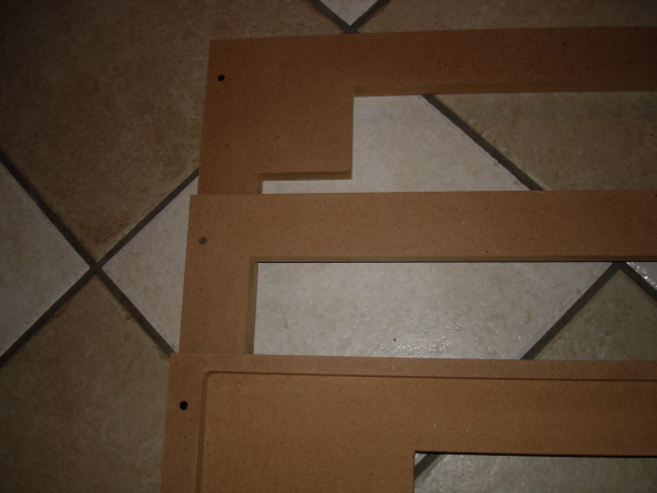
that, I added a square to be cut out so that the area around the bubbler tube would be left open. Now I can fit a 90 degree elbow at the base. You can see that I did not go all the way through on the top section of the base, as I forgot about it and I didn't want to go back again. As it stands, I have 1 1/2"'s to work with and if I need that additional 1/4", I can just use a flush trim bit to open that area up. Here is the front of all three base sections:
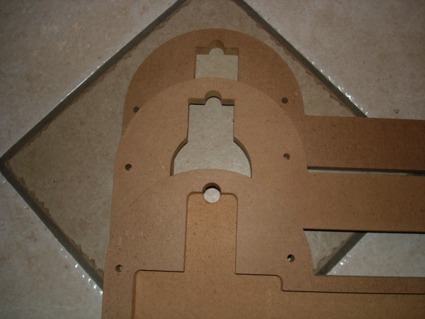
Here is the back of all three base pieces. As I just copied and pasted that top layer, you can see how I changed each piece on the laptop to suit the needs of each piece:
Here is all three pieces sitting together:

Now, I needed to design the pieces that would go up the sides. A couple of things had to be considered. 1. It had to not only be aesthetically pleasing, but also functional. 2. It had to have a 3d look to it, to create "curb appeal" if you will. 3. It had to be able to hold the light lense and the bubbler tube. and 4. It had to be able to easily attach to the shell.
With these things to consider, I started off with some basics. The fatter pieces would be center pieces in the base, the middle, and the top. Skinnier, 1/2" press board would be skinnier and have the responsibility of holding the light lense in place. After those were designed, I started to really look at the shell and see where I could add features to really set the pieces off. If you look, I added a 3/4" wrap around that hooks into the middle of the machine. With the 1/4" black plexi, the bubbler pieces will fit right up to the face of the middle. In the back, I decided to go 1/2" past the edge of the shell. This will allow for some accented trim pieces and give the juke just that much more "curb appeal". In the end, there are 14- 3/4" pieces and 8- 1/2" pieces. Here is an example of the 3/4" mdf middle pieces and a 1/2" pressed board piece with the channel routed for the light lense:
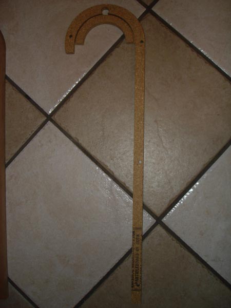

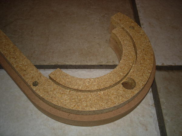
There is to be a 1/4" round over put on each of these to go along with the rounded theme:
Using the 1/4" guide holes, I am using a piece of aluminum rod for demonstration. Here is all of the pieces of the base attached:

Here is a view of the back of the base:
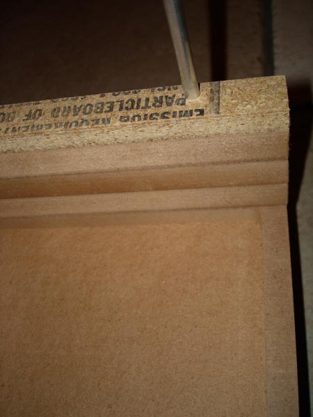

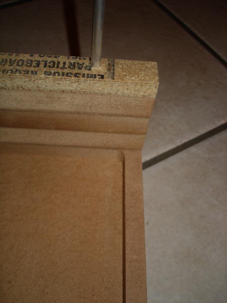
Here is the front with everything in place. Although the light is deceiving, the pieces are alligned perfectly:

Here is the front with the bubbler tube in place:

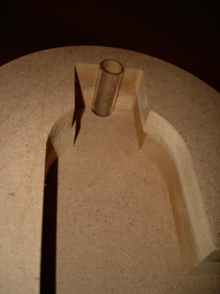
Here is a shot of the underside with the open area for attaching the plumbing to the bubbler:
Sorry for the long post, but I realized that I hadn't been really explaining any of the ideas or concepts. It was a nice break to do this and I hope this will help others in their planning of projects.


 Home
Home Help
Help Search
 Login
Login Register

 Send this topic
 Print
Print Topic: New Jukebox - Wurlitzer style - Spring construction has begun! (Read 58012 times)


