On to the back.
As I've mentioned before, the top and back of the cabinet always posed a big design problem for me. Ultimately the vacuum formed panels along the top, and parts of the back solved the problem of the cabinet's curves otherwise becoming a facade hiding a flat top and back, which I definitely wanted to avoid.
I still had to deal with putting a door or access panel on the back of the cabinet, since the permanent installation of the bezel meant the monitor couldn't go in or out through the front.

I decided to create a panel that followed the contour of the back of the cabinet. I wanted the back to have the same level of finish and detail as the rest of the cabinet, particularly if it is to ever sit away from a wall, where it would be visible. For the surface of the door, I used aluminum perf panel, which has the added benefit of venting the cabinet directly behind and above the monitor.
This perforated panel is bent and held in shape by a 3/16" channel cut into 3/4" walnut sides which give the hatch its structure and add a bit of trim to the back.
It gets bolted into place, since it'll rarely be opened, and since I needed to child proof it against curious little hands, given it leads straight into the neck of the monitor and access to the anode cap
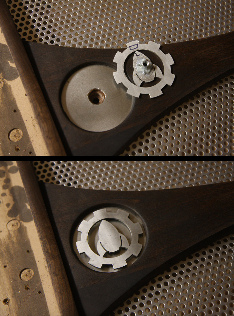
The bolts (and nuts) that hold the door in place are then hidden by a pair of stainless steel rocket logos (waterjet cut by Cornchip) which spin down onto the remaining length of the bolt shafts and recess themselves into the walnut handle across the mid section of the door.
Confused? So was I.
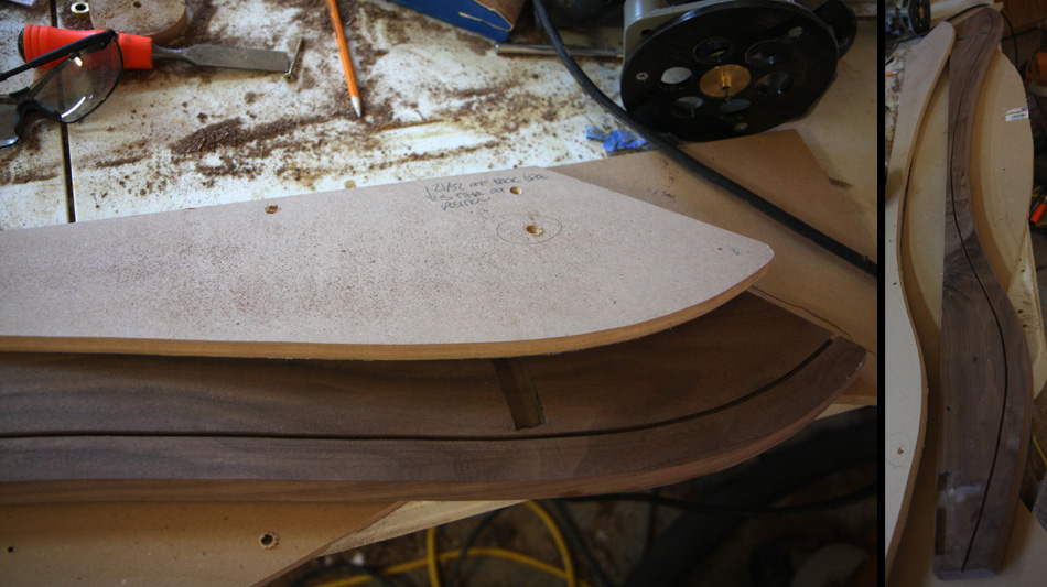
First I used the same template approach I used on most of the cabinet to cut the walnut door sides. That is
.
1) Create the shape in a graphics program (Illustrator)
2) Print out at full size
3) Spray mount on MDF
4) Cut the MDF to the final shape
5) Use the MDF as a template to route the actual wood.
Once I had two matching sides, I rounded their edges with the router then screwed them onto a sheet of MDF to hold them in position next to each other (back to back) while I routed the various dados I'd need to brace the door with poplar
ummm
. braces. This allowed me to get the dados in exactly the same location on both sides quickly and accurately. I was really really nervous about keeping the door square
partially because of the fact that, like the rest of the cabinet, it toenails down at an angle (wider at the top than bottom, blah blah blah) and partly because there simply wasn't going to be much structure holding it together. It was going to be like a very large and curvy picture frame, with quite a bit of twisting/flexing torque applied to it by the large sheets of "forced into position" curving perf panel. Anyhow, I tried to keep things as accurate and symmetrical as I could.


With the dados cut, I marked their locations on the poplar braces that would get slotted into them. Hoping to create a sort of multi directional self stabilizing auto aligning locking mechanism structure, I continued the dado along the poplar. There are two of these poplar braces, each in the shape of a T as you can see in the wider shot.


Next I measured the horizontal dimensions for a handle to be cut from walnut to give the center of the hatch some support, and allow for an attachment point (the bolts mentioned above)
I created a template for the handle (as detailed above) and routed it from walnut.
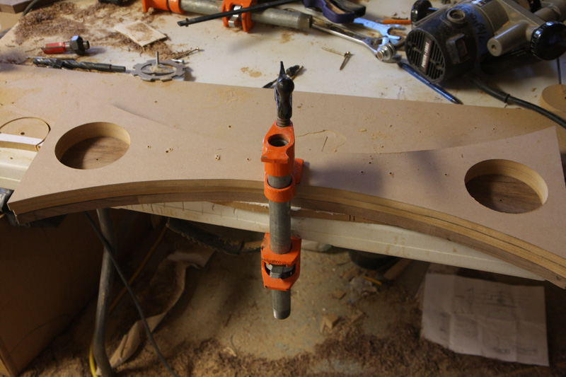
Front:
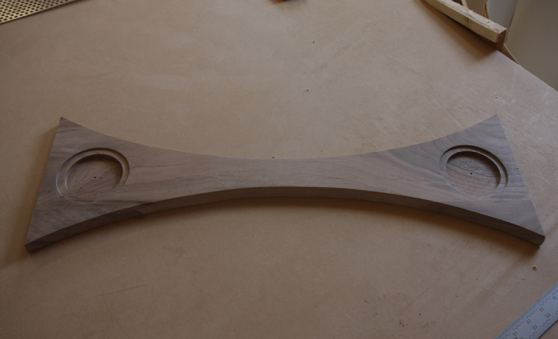
Back:

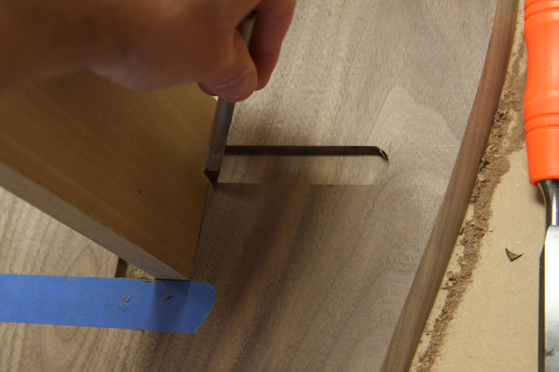
Using the same template I had used to cut the door sides, I inset a 3/16" channel along the inner face of each side to allow the perf panel face of the door to be held inside.
After measuring the length and various widths I needed for the perforated panel, I trimmed it to the appropriate shapes to fit into the angled door. The perf panel wobbles and shakes like crazy when being cut. Sandwiching it down made that a lot easier. Who'da thunk?

I tried using epoxy to attach some threaded "weld nuts" on the back of the stainless logos with mixed results. Ultimately one is (so far successfully) attached with epoxy, while the other failed and was reattached using JB Weld
technically an epoxy I guess but apparently much much stronger and better for smooth surfaces than the stuff I was using.
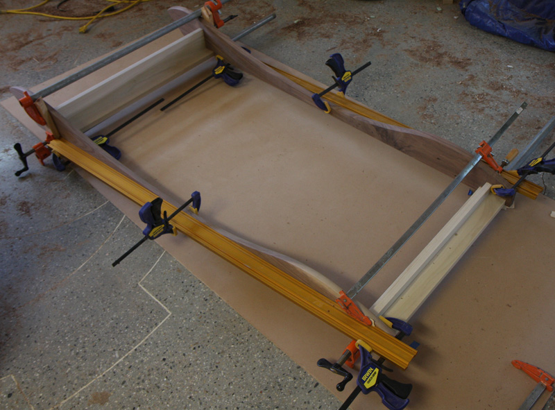
After measuring the diagonals to check for square, I glued up the door, sandwiching the perf panel in between the sides in the slot I had routed.


After the door was glued, I attached a heavy grade vinyl window screen material to the back of the perf panel to prevent the previously mentioned curious fingers from poking a coat hanger through the back and into the monitor neck
..*thinks of Nostrebors avatar pic*
Here are pics of the doors curvature


 Home
Home Help
Help Search
 Login
Login Register

 Poll
Poll
 Send this topic
 Print
Print Topic: Mission Control Project: 5 years on, what to do with the leftovers? (Read 790531 times)


