Update time!

The LED buttons I plan to use have arrived. Here are pics of them:
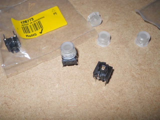
I bought three buttons (one a spare) and the caps came in a pack of ten. So a few spares there then

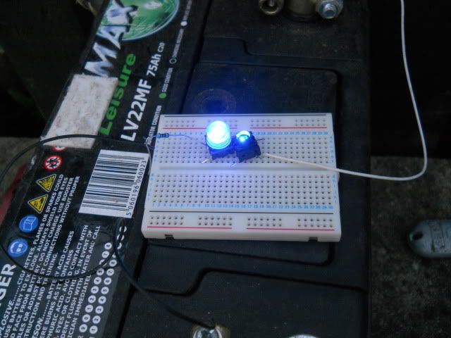
Couldn't resist a quick test to see what they looked like lit up.
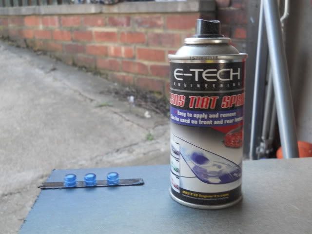
It wasn't until a bit later that I hit upon the idea of spraying the caps blue with some of that lens tint that boy racers use. Those spare caps came in handy... if it didn't work out I'd still be OK. But as you see they came out very nice. Look more in keeping with a real Robotron now. They light up a little darker than in the above pic but somehow it's nicer. More of a deep blue.
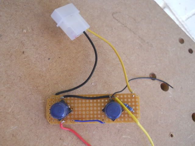
Here's the little board I put together for the final circuit. My soldering skills still need some work, it's not exactly professional under there.
But it all works fine. I also wired in the button wires and earth so I can just tap into them later. In hindsight I wish I'd lengthened the wires to the 12 volt molex for when the control panel is ever opened, but that can be sorted out later.
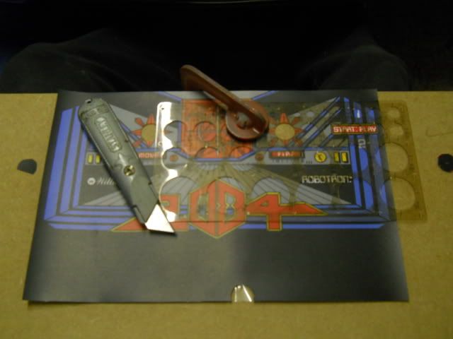
I was thinking of various ways to cut out the holes in the artwork. I had to be as neat and accurate as possible. No dust washers or button shoulders can hide any bad cuts here. I eventually used a circle stencil and a Stanley knife with a new blade to cut them out. I'm pleased with how it turned out. Had this come out badly I'd either have to live with it or get new artwork printed.
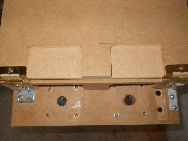
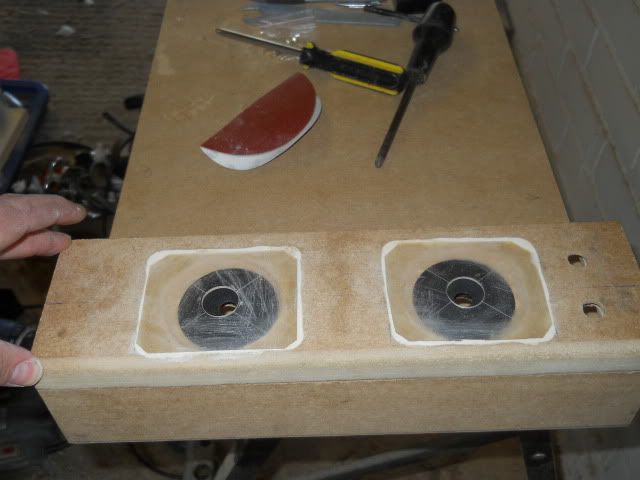
The two pics above are one stage of the panel build. You can see I routed out as neat as I could to get the joysticks to fit. But this was prior to getting the PCB button board or the locking latch installed.....
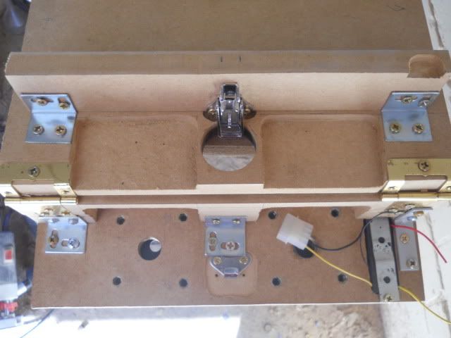
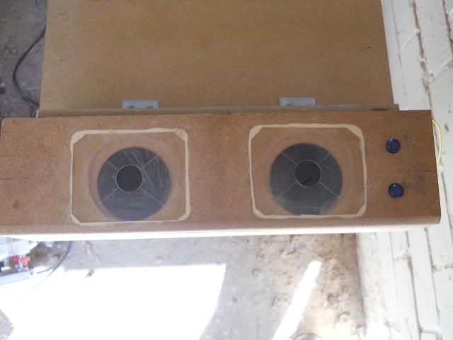
.... so here's where I'm at now. Not so neat as before.

I fitted the circuit board in position and then padded out the underside of the board with adhesive rubber strip till it was slightly proud of the underside of the panel. Then I screwed the small metal strip over this to hold it firmly down. I had to use a different bracket on the right of the pic in order to fit the PCB in. I also had to fiddle around a bit to get the latch in place positioned perfectly. To lock the panel you just put the latch in place through the hole in the base and pull it down closed. It's not spring loaded like an arcade latch so it needs locking in place with a small bar or padlock through the hole. But when locked the panel is firmly secure and does not wobble or move at all.
Again, you can see that everything isn't perfectly neat looking. It was a case of routing out bits and pieces to get things to fit. Brackets and screws don't match as I'm making do with stuff I have lying around from previous projects.
Here's the top view of the panel with the buttons installed. This panel is now finished and just needs artwork installing. Not doing that till the end though.
I've also had to make a change of direction as regards the monitor. I cannot use the CRT I intended to use as it simply won't fit in the project well enough. The depth is just way too large. It would mean extending the depth of the cabinet by around 70-80mm which would just make the side profile look odd. I could get away with 10-20mm but having drawn out the side profile necessary it instantly looked silly. So I'm gonna go with an LCD, but this does have some advantages. It means more room to get the other bits in, a lighter end product and I can also use the original bezel art albeit at 50% size.


 Home
Home Help
Help Search
 Login
Login Register

 Send this topic
 Print
Print Topic: Robotron bartop - Finished!!! (Read 32148 times)


