Ok folks here it is a tutorial for a button flashing LED mod that I posted on another forum. The stick is one you may recognize as my second Dymondwood stick. It came back for an issue with one of the buttons and a problems with the pad. I offered to do this upgrade for the customer and he jumped at it.
Parts needed.
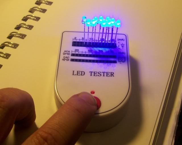
LEDs, one for each button
Resistors, one for each LED scaled for the voltage being supplied
Perf Board to mount the electronics
A hex inverter (Toodles recommended the 74HCT04, but also said that any of the 7404 family will work like the 74LS04 or 74HC04)
Wire, 26 or 24 AWG
Tools needed,
Drill and drill bit to fit the LEDs
Soldering Iron
Rosin core Solder
Screw drivers
This particular mod is for 10 buttons so I am using 2 chips. This can be done with one chip for 6 buttons as well.
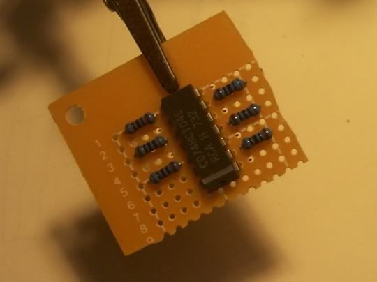
First step is to mount the chips to the perfboard. Note the orientation, the white stripe helps line things up.
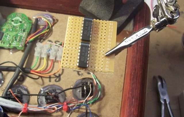
Next step is to identify the legs of the chips and install the resistors for the LEDs. Notice that each chip has one leg for the power and one leg for the ground.
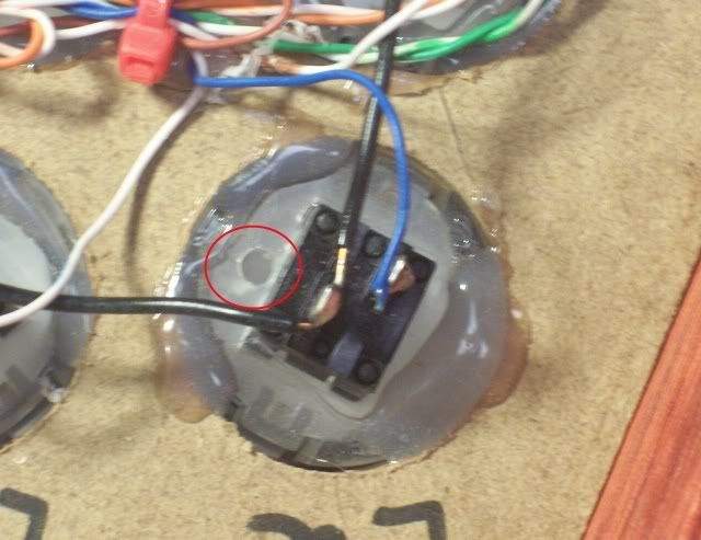
Now drill a hole in the buttons to fit the LEDs. My LEDs are 3mm so a 1/8" bit is perfect. You can also glue the LEDs into the holes at this point. Make sure to test them first. Be extra careful if you choose to use supper glue. It can drip into the button and ruin it.
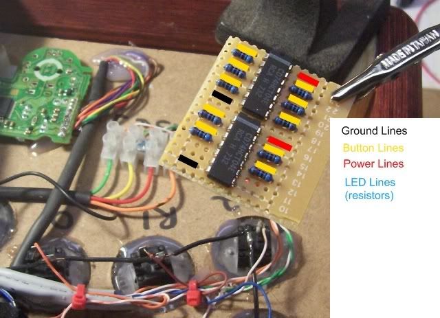
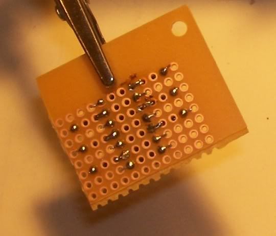
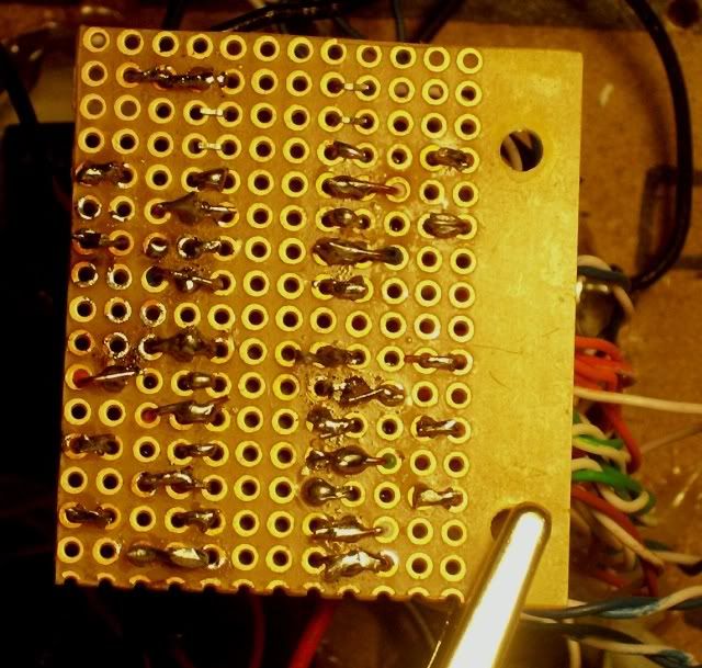
When using Perfboard there are small copper disks around each hole but they are not connected to each other. You have to create a bridge from one hole to the other as you can see in these two pics. They are the same board just top and bottom views.
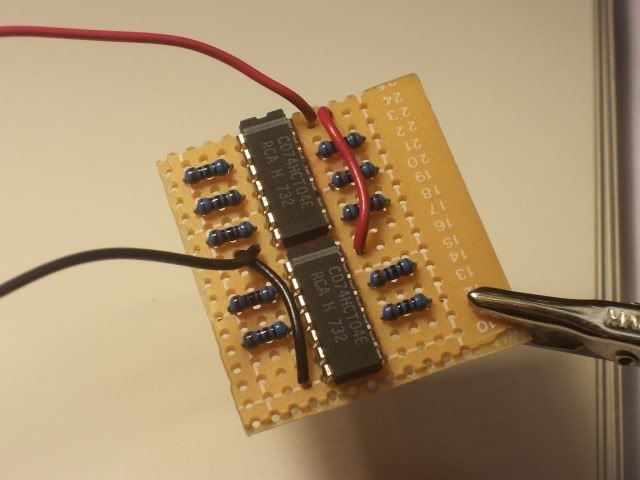
The first wires I solder in place are the power and ground lines. I just jumpered them from one chip to the other.
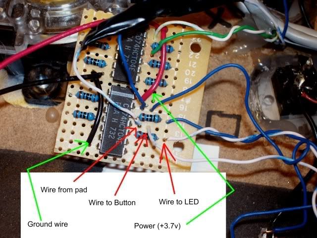
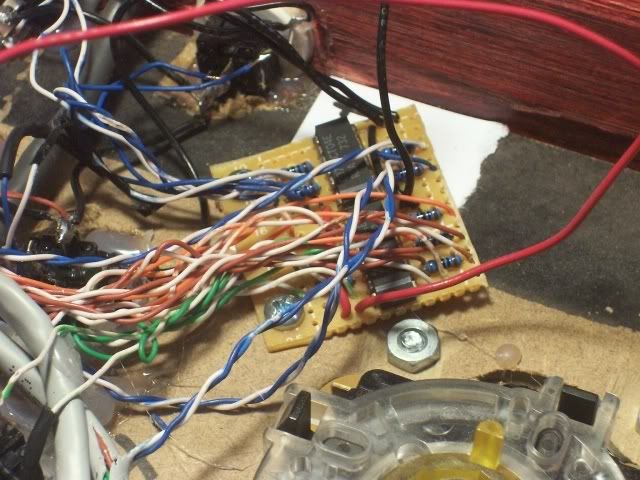
Here is where the magic happens. The wires from the pad, to the button and anode of the LED are added to the perfboard. Also notice the holes drilled in the perfboard are for mounting the board in the case. It will be real difficult to drill them after all the wires are added.
Here are all the wires soldered in place and the board screwed to the case. I used Cat-5 network cable to help keep things straight.
And here is the board's underside.
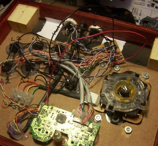
The final step is to daisy chain the grounds on the LEDs and connect them to the ground from the pad. Then connect the ground and power from the perfboard to the ground and power on the pad. In this case I connected the ground to the daisy chain ground on the buttons.
Finally here is a short vid showing the working end product.


 Home
Home Help
Help Search
 Login
Login Register

 Send this topic
 Print
Print Topic: Kaytrim's Kustoms Back in Action (Read 115553 times)


