Here is an update on how things have progressed. I made the control panel from 6mm thick MDF. Now I know that this is not very thick for the purpose of control panels, but I intended to mount this on top of the metal panel already there. Or should I say a framework of the original panel! I didn't want any thicker than 6mm as the surface of the panel would then be sitting above the T-molding at the sides. Here's a picture of how I did this.....

I basically made up a template panel by measuring where everything was going to be.... the spaces taken by the joysticks, buttons, trackball etc. I then placed this on top of the metal panel and jigsawed out holes for my finished panel to drop into. It doesn't look pretty, but it does the job well. Once finished I could then place the template on top of the final wooden panel to match up all the holes for the mounting screws.
Here's a picture of the underside of my final panel....

I made up some spacers for my T-Stick+ joysticks, as I like them to be set low down. I prefer my joysticks to be short and stubby. Also, you can just make out the grooves that I cut into the panel for the trackball wheels to rotate in. I had to do this to get the trackball itself to lift high enough through the panel. I didn't want to use the mounting panel if I could help it as I wanted a totally flush surface for the artwork. Here's a pic of my Ultimarc trackball unit with the top half removed.....

I was a bit worried that all sorts of springs and fittings etc. would fly everywhere when I did this.

But it was simple.... just unscrew the three retaining screws, lift off the top cover and pull out the ball. But you still need to watch the rollers and optical wheels as they will now easily fall out if the unit is turned upside down. To fit the trackball up I now needed a suitable spacer to get exactly the right height. With a bit of mix and matching I found some oversize nuts that were a perfect fit....

In this picture you can see how close the Oscar Model 3 spinner sits to the housing of the Ultimarc trackball. I think there's about 3 to 4mm in it max. But it was measured precisely, and I can't stress the importance of double checking all measurements before cutting and drilling any panels. Also, I kept the Player 1 and 2 start buttons in there original place. They actually help to clamp the wood and metal panels together without need for extra screws etc.

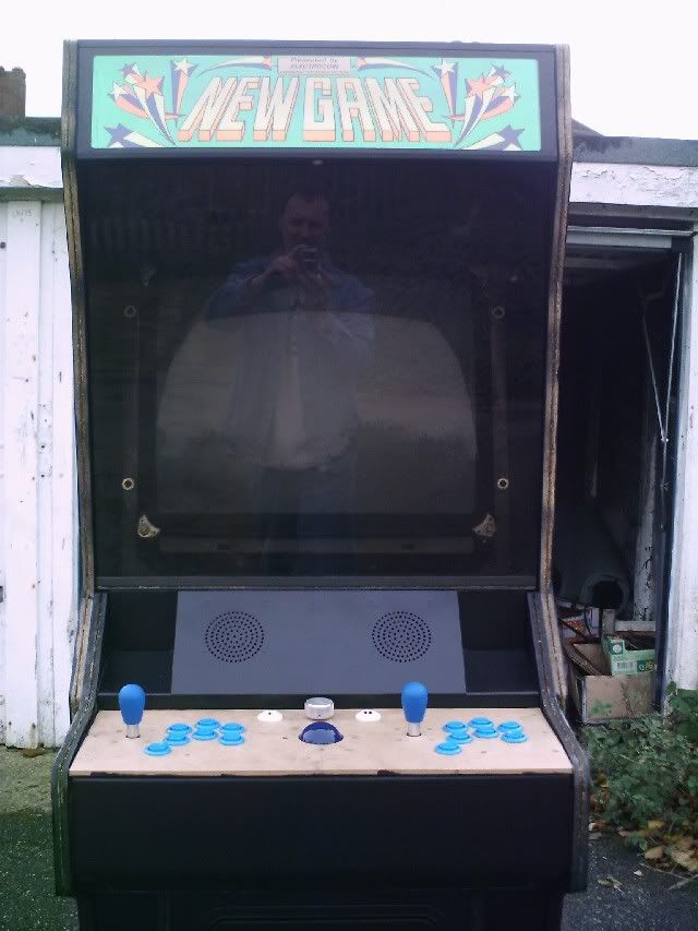
A picture of how it looks from the top.... all screws and bolt heads are recessed and will be filled in later.

Now for the painting. I ripped out all the old black T-Molding and sanded the edges down where necessary. The cabinet is in very good shape for 15 years old, but there were still one or two areas that needed a bit more attention which is to be expected. I decided to spray paint the cabinet with aerosols..... which turned out to be a mistake! Whether it was the paint itself, or my spraying technique I'm not sure. But the results were crap!

Black is the worst colour to get right, as any imperfections will show more than any other colour. There were shady bits and uneven parts all over the place. I wasn't happy and ended up buying a tin of black satin paint from B&Q for less than a tenner and used a roller kit to apply it. The results were much, much better! Not perfect by any means, but good enough for me.....


I also painted the control panel front and underside using a roller, but I did use aerosols for the speaker housing and coin doors which did come out nice....

The original speakers were removed and I used a pair of Cambridge Soundworks 2.1 speakers that I had left lying around from when I'd upgraded my home system to 5.1 surround. They fit nicely in the gaps of the old speakers as though they were specially made for it....

I then isolated the switching power supply from the cabinet. I was a bit worried about this as I'd no previous experience at all of arcade cabinet wiring. But after some very helpful advice from this very board (Thanks guys!

) it seemed I was worrying about nothing. A simple block connecter was unplugged and the job was done! I decided to leave the switchablle power unit installed though, as I can still play Jamma boards if I want to at a later date.....
EDIT: 28/10/04 I slightly altered the way I isolated the switching power supply today. By simply unplugging the block connector I was also disconnecting an earth wire as well as the live wires. Now.... this earth wire may have only been for the AC power supply, but I couldn't be 100% sure as it was difficlut to trace the wire back in the loom. So I played it safe and reconnected the block connector, and instead disconnected the live brown and blue wires direct at the switchable power supply (and taped them up properly!). This leaves the earth wire intact just in case something else is earthed through it. I feel this is VERY important so I put this EDIT note in.


And here's where I'm up to now with my lovely 2.25" transluscent ball I got from The Real Bob Roberts. This will be illuminated when the cab is finished.....


More updates later!


 Home
Home Help
Help Search
 Login
Login Register

 Send this topic
 Print
Print Topic: Dave's Mame Arcade - made in Leeds, UK... UPDATED 23/11 (Read 10654 times)


