This video gives you some good information about relay modules that might help you find one with the right features.
It focuses on Arduinos, but your coin recognizer signal will work like an Arduino output configured for "active low".
Would this one be better? https://www.aliexpress.com/item/1005006151364343.html?spm=a2g0o.order_list.order_list_main.17.59d51802fa9FNl-
Looks like this one is "active high".
This video of a similar module shows it being triggered by 12v at 4:00 - 4:15 so it is an "active high" device.
- I don't see any jumpers for changing the input between "active high" and "active low" mode on either of the boards.
The coin mech I will be using is a TW-131
That model looks like a standard 12v "active low" coin recognizer.
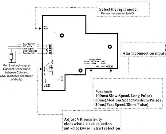
The good news is that these devices have an adjustable pule width so no worries about the coin signal not being long enough to trigger a relay.
You will need a 5v Zener diode if the input is 5v.
- Connect the cathode (band side) to the signal line.
- Connect the anode to ground.
- These connections reverse-bias the diode and allow it to work as a voltage regulator.
- The signal line to the left of the diode will be at 5v.
So if i connect the trigger line from the coin mech into this modules trigger connection, and also the trigger connection into a zero delay - you are saying that this would surge 12v into the zero delay unit?
The output on the coin recognizer is 12v so without a 5v zener diode to regulate the output down to 5v, it will fry any 5v encoder.
The larger problem is that your coin recognizer is "active low", but most ZD encoders are "active high".
To test if your ZD encoder is active high or low, put the black lead of your multimeter on the USB outer shell (ground) and put the red lead on one of the tied-together "common" input connector pins -- they are the ones closer to the edge of the board.
- If you have a 5v "common", it is an "active high" device.
- If you have a 0v "common", it is an "active low" device.
You can see the wide light-green "common" backplane running along the outer edge and connecting with the outboard pin of each wire pair connector on the near side of the board.

-----------------------
To use your active low coin recognizer with an active high ZD encoder and an active high time-delay relay, you need to add a second relay module that is active low as shown in the attached image.
- You can use a timer relay that is "active low". Instead of connecting the 5v Trigger input to purple as shown, connect it to the green trigger input on the other relay -- this connection must be to the right of the Zener diode for it to be regulated down to 5v.
- To ensure that the top-center relay is "active low", get one that has a jumper to select "HIGH" or "LOW" as seen at 2:44 and 6:19-7:52 in the video at the top of this post.
Scott


 Home
Home Help
Help Search
 Login
Login Register

 Send this topic
 Print
Print Topic: A 12v delay relay that activates from a switch (Read 70229 times)


