I have concave translucent buttons on my cabinet I am building. I plan to drill them and install 5mm leds
Sounds like the approach shown in the wiki.
https://wiki.arcadecontrols.com/index.php/Lighting_Microswitch_ButtonsNeph did a variation on this by drilling through the microswitch holder so the LED wires couldn't shift and get in the way of the plunger leg/microswitch nub.
https://forum.arcadecontrols.com/index.php/topic,108719.msg1177518.html#msg1177518
I would like to buy these leds:
https://www.amazon.com/dp/B08GRD9DCV?smid=A4796MTJVO3KW&ref_=chk_typ_imgToDp&th=1
One thing that concerns me about these is that the listing doesn't indicate if they are wide or narrow angle LEDs. You might end up with a "hot spot" in the middle of the plunger.
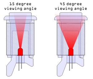
If the LEDs are narrow angle, you might experiment with using 2 or 3 of them to side-light the button, either through some diffusion material like
this guy did
or design/3d print a bracket to hold the LEDs horizontally. You might need to route a pocket for the diffusion material or bracket.

I am unsure what connectors to buy to stick on the ends so I can plug them into the ipac. I am also unclear if I can just stick them right onto the 4 pins of the ipac or if I need to stick only 1 wire on the ipac and the other go to ground ... somewhere..
The pins on the IPac Ult. I/O are "Dupont" connectors.
You can get long pre-crimped M-F or F-F Dupont jumper wires, cut off one end if you got the F-F ones, and use a euro-style terminal strip to join the jumper wire to the LED wire.
When you connect the jumpers to the Ult. I/O board, the order for the pins is written at the bottom of the board: +RGB on the left and BGR+ on the right.
- Connect the LED anode (the resistor side on the LEDs you're looking at) to +. This is the operating voltage for the LED.
- Connect the LED cathode to the R, G, or B ground channel. The Ult. I/O board controls the brightness of each LED channel by controlling how much current can flow through each of these channels.
If you use more than one LED per button, connect the anode wires for that button's LEDs together on the LED side of the terminal strip and connect one wire from the jumper side of the terminal strip to the + on the Ult. I/O.
- Use one ground channel (R, G, or B) per LED.
Set LEDBlinky color for all buttons to white so all three channels will conduct equally if an LED is connected and LEDBlinky sets the button LED to ON. If the LED cathode is on "R" and LEDBlinky tells the Ult. I/O to light the button blue, the LED won't light because only the blue channel will conduct.
Scott


 Home
Home Help
Help Search
 Login
Login Register

 Send this topic
 Print
Print Topic: Addon LEDs for buttons - please help (Read 1911 times)


