The buttons are wired up to the KADE but the 5V on the KADE doesn't light the buttons. I will get a multi meter out and see if the 5V on the KADE is working.
The Minimus AVR can only provide a limited amount of current (50 mA?) from that 5v pin.
Typical LEDs draw 20 mA each so you'll need an external power supply if you're running a bunch of LEDs.
I wished there was a lock on the shift button feature on KADE so you can map both analog controllers for games like Halo.
Some of the firmwares have a "double-click HWB to shift lock" feature, but I don't see that note on the Xbox firmware.
If nothing else, you can use a rocker or toggle switch on the HWB input to constantly enable shifted functions.
- Switch open for normal functions.
- Switch closed for shifted functions.
--------------------------------------------------
Let's try this part again.

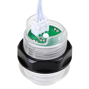
Looking at the connector with the three wires moving the button shown in the image with the connector on the left side the wires are 5V (red dashes on the cable), Data (smaller red dashes on the cable), Ground (red dots on the cable).
The button picture shows no red markings on the wires.


To be clear, let's assign a letter to each wire in the picture below:
- Left wire in the picture = A
- Middle wire in the picture = B
- Right wire in the picture = C
Which letter is 5v?
Which letter is Data?
Which letter is Ground?
The middle pin (DATA) connects to the lower pin (GND)to operate. so active low devices. Looking at the EG Starts encoder board underneath will show all traces joined for 5V, so I am not sure how the demo light buttons work on the KADE if they are connected in series.
I'm
guessing that this part of your post is referring to the bottom row of twelve 3-pin "Group 2" connector pins on the PCB, right?
It sounds like you're saying that as you look at the "Group 2" connectors in the picture below:
- The 5v pins are toward the center of the board.
- The data pins are in the middle of the connector.
- The ground pins are toward the outer/bottom edge of the board.
Does that correctly describe each pin's function and location in this photo?

Scott


 Home
Home Help
Help Search
 Login
Login Register

 Send this topic
 Print
Print Topic: Cheapo Optical Spinner (Read 8571 times)


