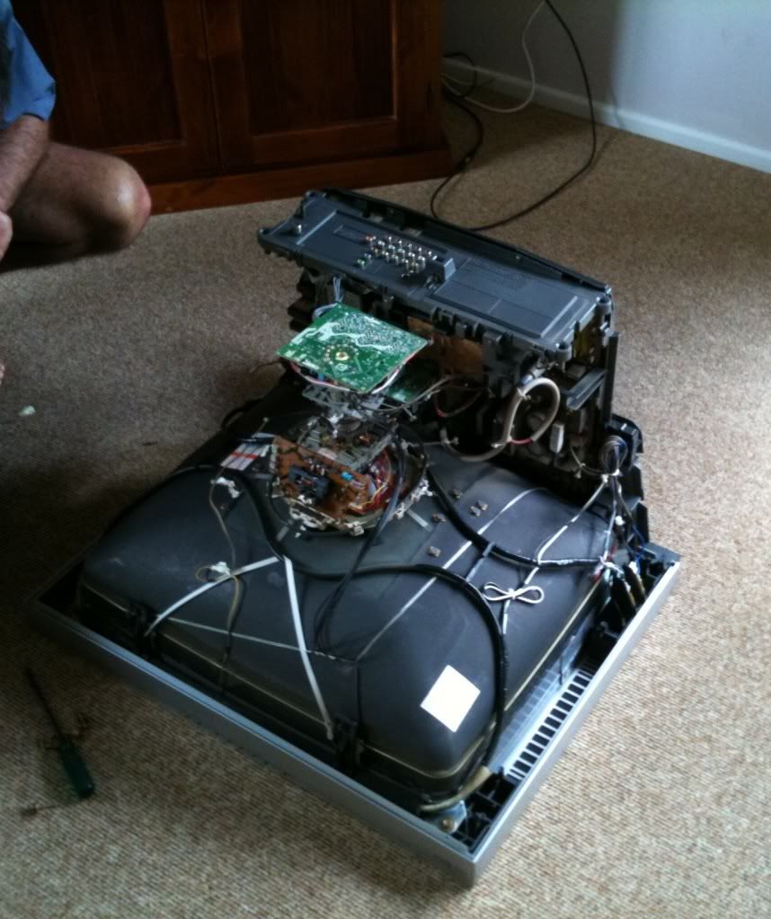
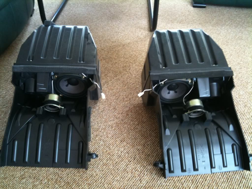
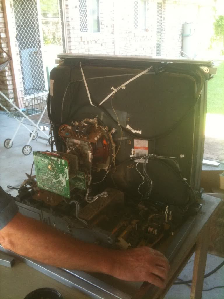
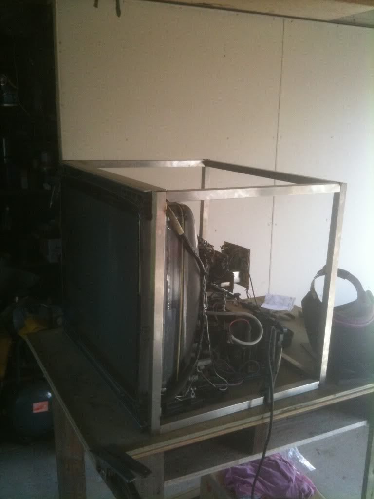
MONITORThe first purchase I made was the monitor, as the width of it would help determine the dimensions for the rest of the unit. I went with a CRT television because I wanted a cheaper screen that I wouldnt be afraid to pull apart. Additionally, I wanted some old school authenticity and at the time I was also determined to use a pair of light guns. I managed to find a Sony Trinitron 68cm on eBay for $41. I picked it up on 1/1/11 and promptly began to gut it and discard unwanted parts, including the speakers.
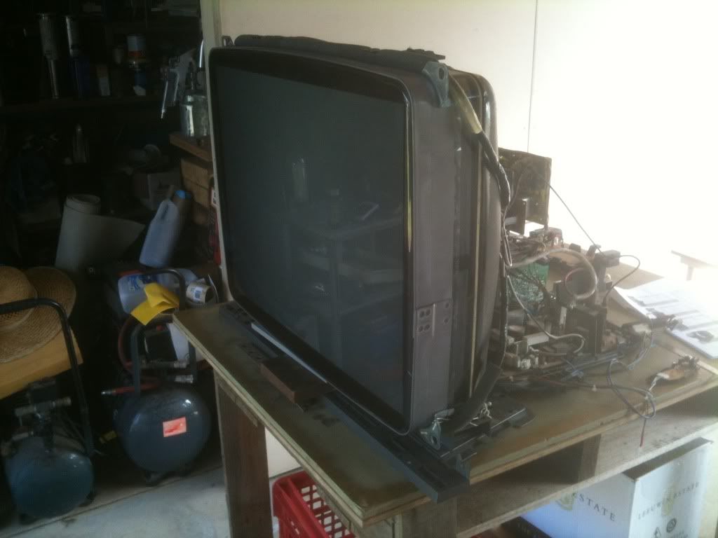
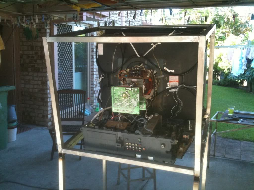
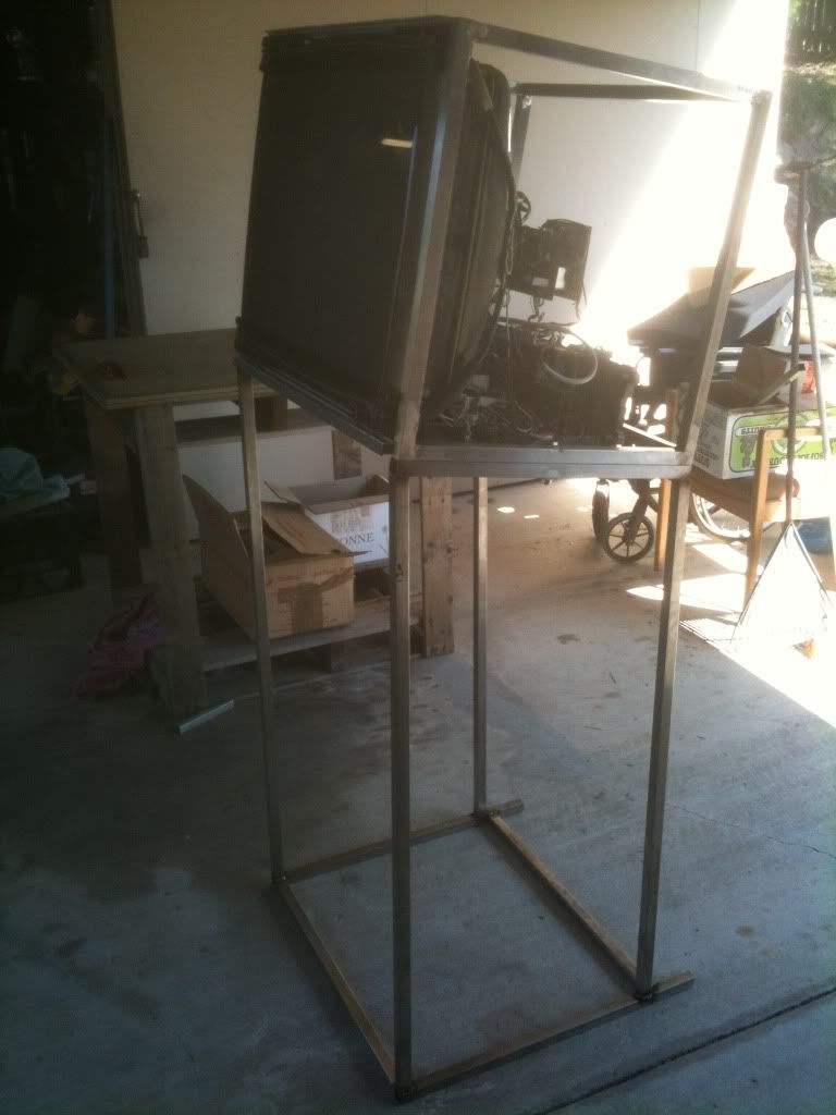
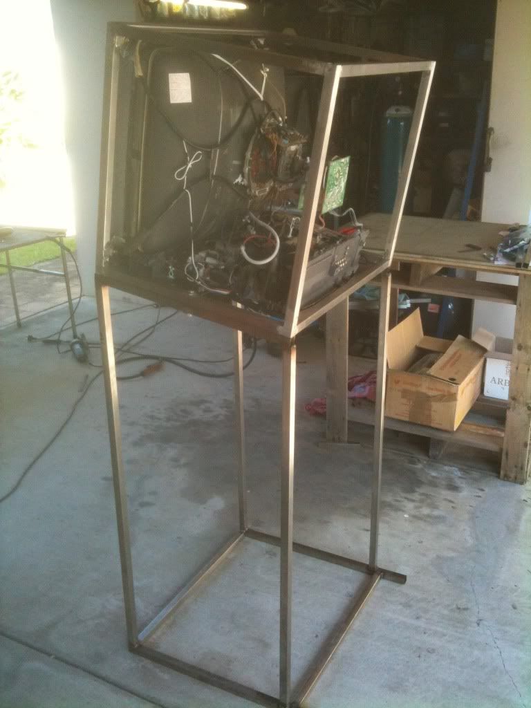
Once I had broken it down, it was time to box it. We had chopped up the load-bearing frame that held the screen itself, so that we could fuse it directly with a stainless steel box that would then become continuous with the rest of the stainless frame.
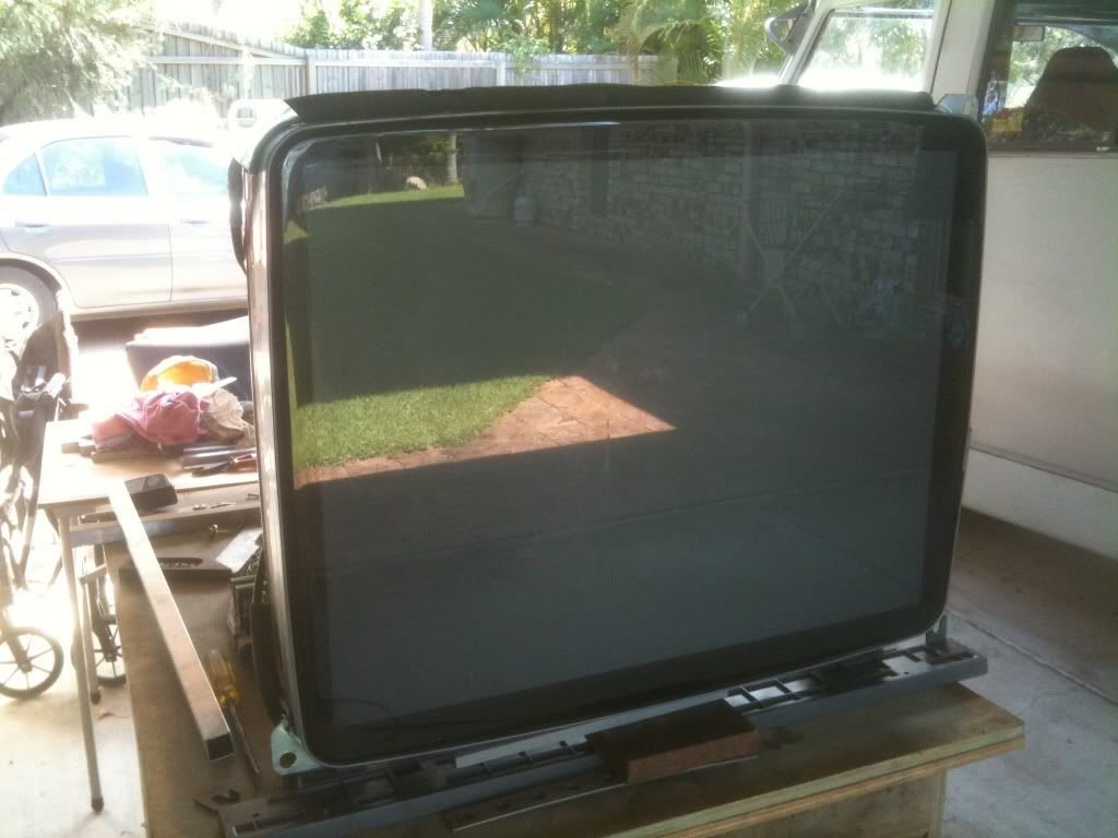
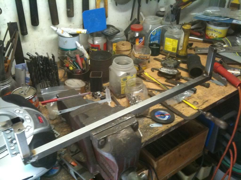
After recycling some screws and welding on some stainless tabs, we were able to weld some stainless steel tubing into the existing screen frame.
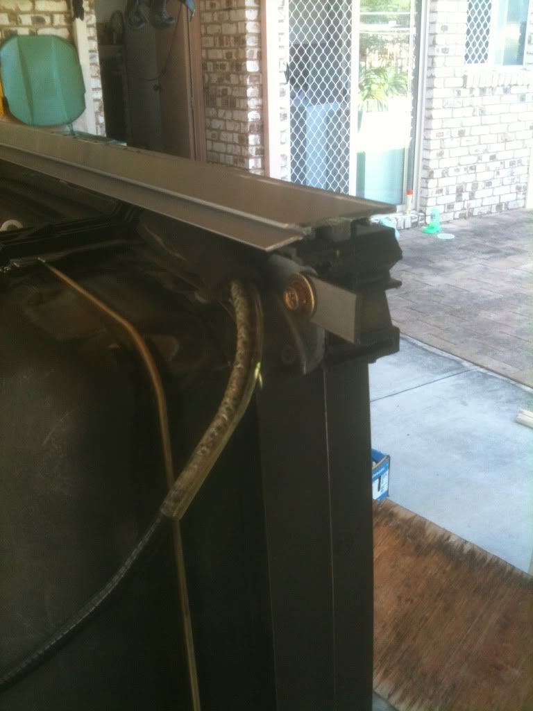
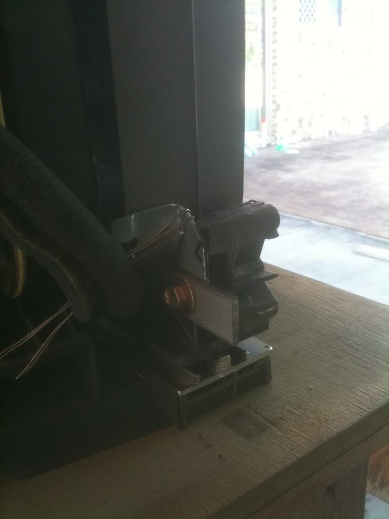
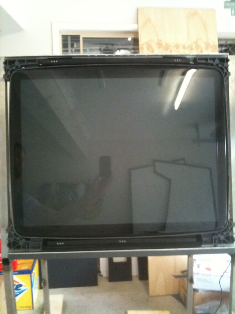
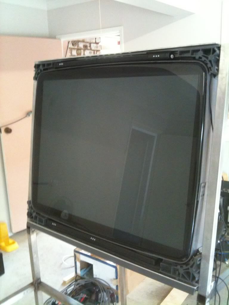
It was then just a matter of welding more tube on to cube the monitor, essentially to replace the discarded original plastic exterior. This gave it rigidity and would make it easier to combine with the cabinet.
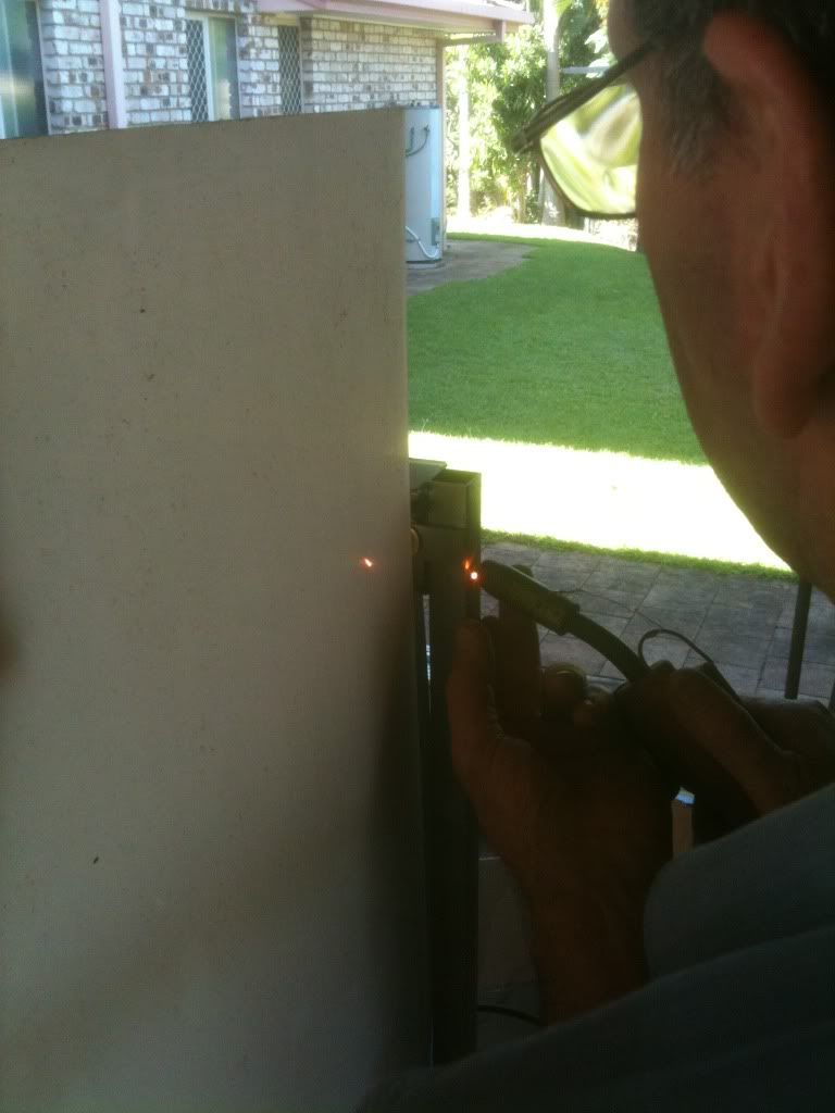
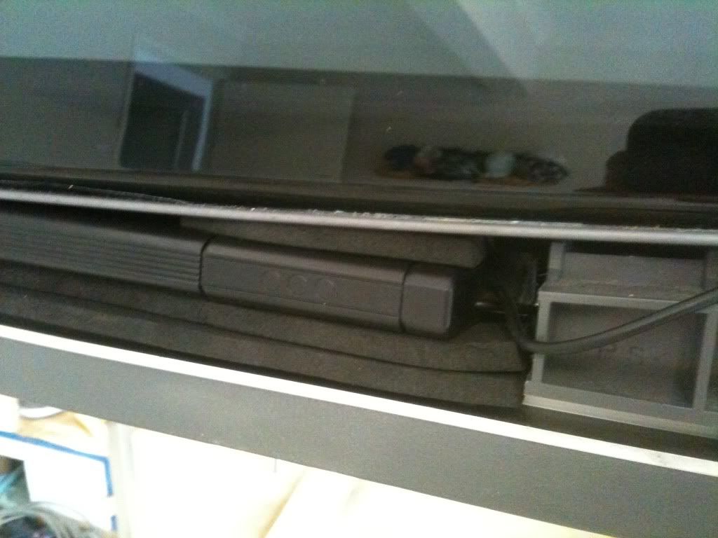
Later on in the project I decided to go with EMS Topgun IIs. I loved the look of these guns and, combined with the recoil function it was an easy choice to buy two. But it then became a problem to decide on where to put the LED bars, since I had intended to hide all possible fixtures. Luckily by this stage I had not completed the bezel artwork and the solution presented itself hide the bars behind the artwork! Luckily the LED bars fit nicely above/below the screen within the confines on the stainless frame. So I simply adjusted the artwork to accomodate the sensors (by placing void areas on the bezel) so that they would be able to work from behind it. They were fixed tightly in place with some foam. More on the bezel later.
 CONTROL PANEL
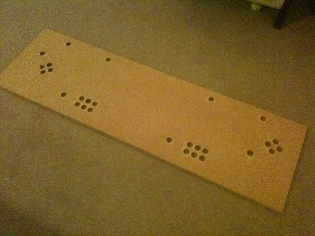
On to the control panel. I bought a cheap piece of MDF to use for practice. I designed a layout and drilled all holes out. I wasnt too concerned about flush mounting a joystick in a practice piece so I just drilled a hole.
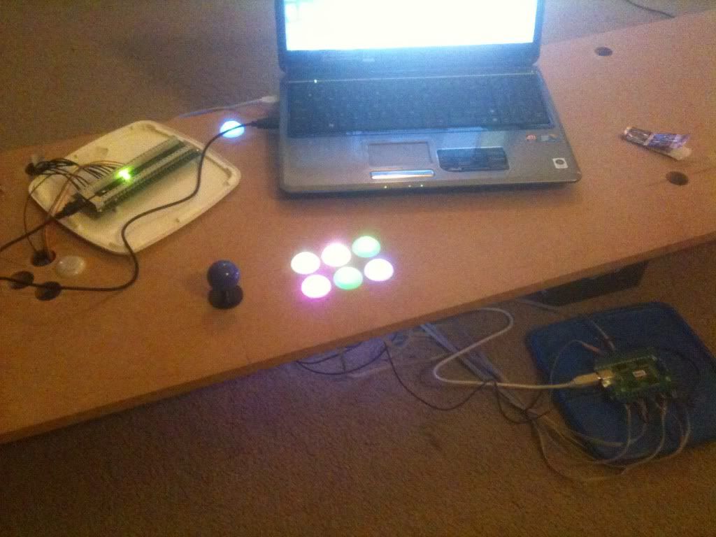
By this time my pushbuttons and joysticks had arrived so I set up one player and tried my hand at wiring. After a few games and trials with the LED software I was satisfied that I would be able to put this together.
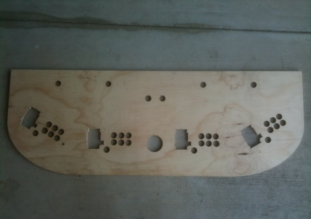
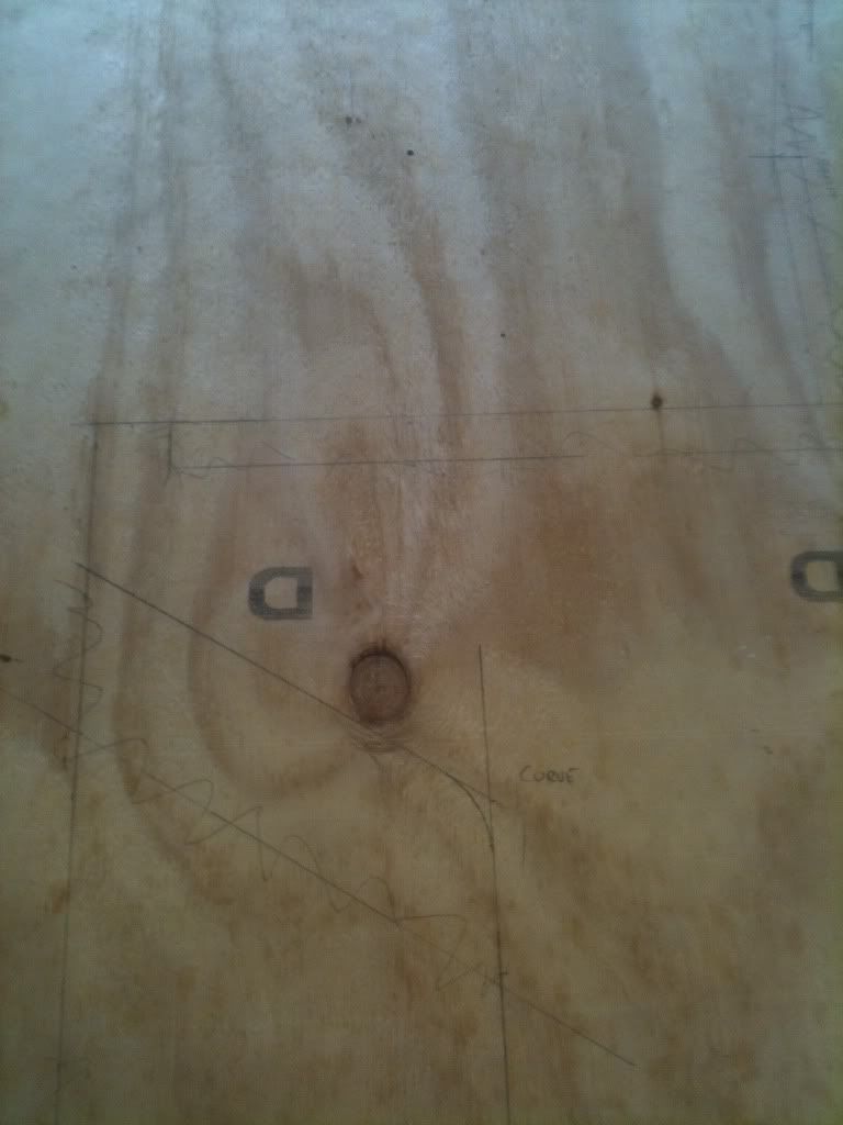
I used the practice control panel to help me decide on the proper layout of my buttons. I decided that placing the outside players (3 and 4) at 45 degrees close to the screen was sub-optimal. The screen needed to be as close to perpendicular to the ground as possible so as to accomodate gun games, and putting those outside players close in there at 45 degrees was no good. I concluded that 10 degrees tilt on the screen would do it. Since I didnt really care about space considerations, I decided I would bring those outside players back away from the screen more level with 1 and 2, and orientate them at a similar angle. I also would space them sufficiently far apart so there would be no elbow-bashing. I found that 30 degrees was a fair balance between distance from screen and angle looking across it. I made up the control panel dimensions in photoshop with actual measurements and printed it out. Then I simply laid it over the appropriate piece of ply and transcribed. I would later use those actual dimensions in photoshop to create my control panel artwork. The plywood I used was 16mm (same as the cabinet sides) since I wanted to use the same t-molding on each.
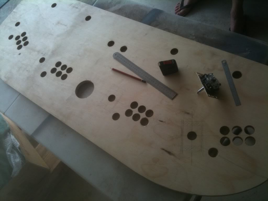
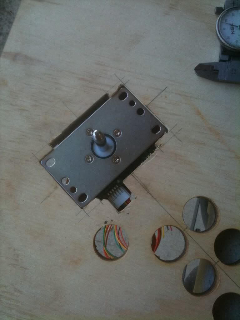
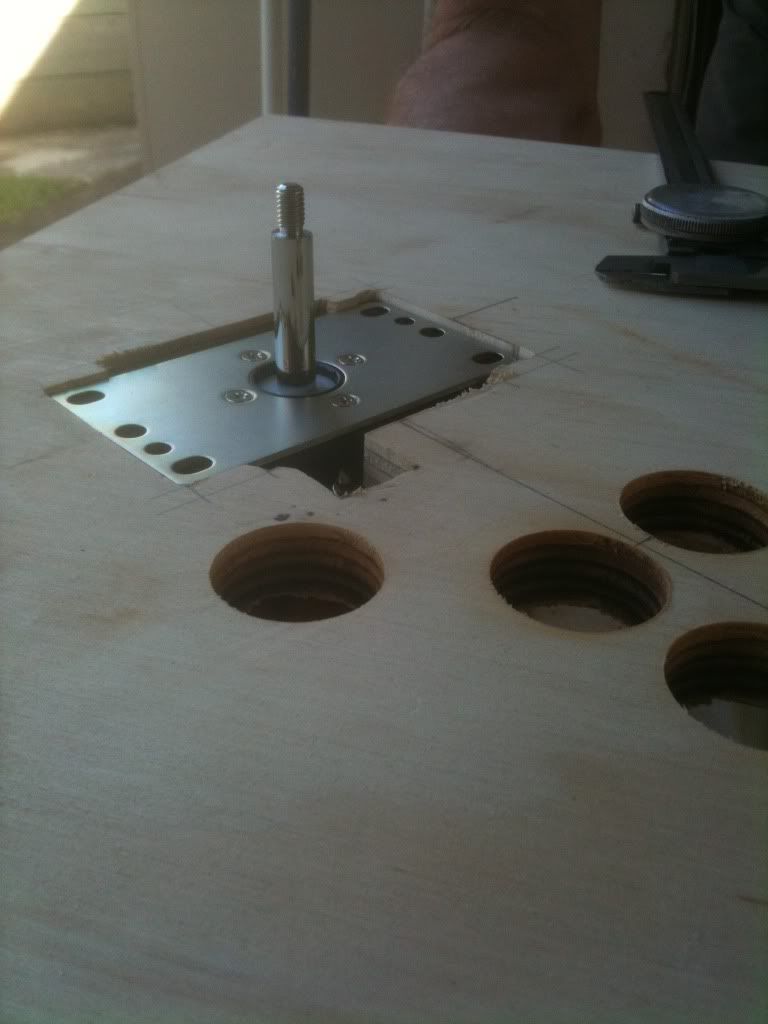
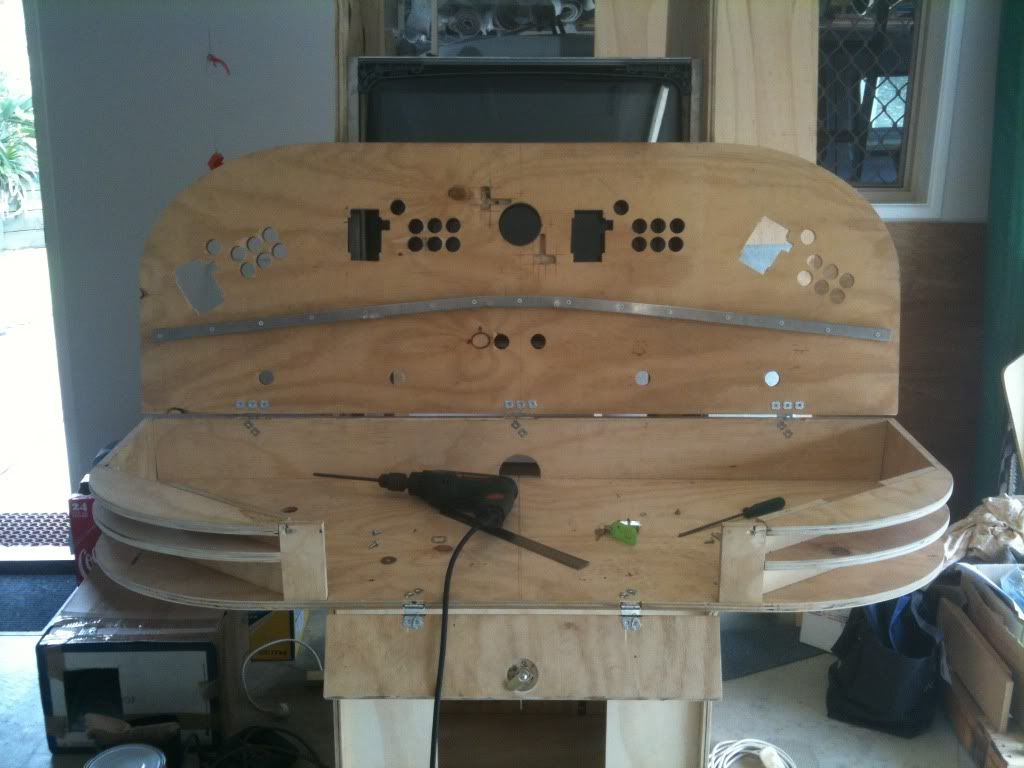
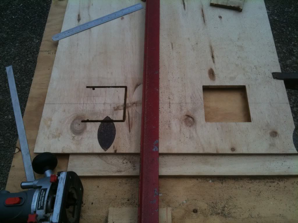
I used a hole-saw to cut out the player buttons. I then used a jigsaw to cut out the joystick mounts and curved edges on the panel. I was going to flush mount the joysticks, so I allowed for the plate to sit flush, and also for the square-shaped components below. In retrospect, another way I could have done this would have been to just jig the plate and then router from underneath to allow for the components. Im not a fan of complicated/unnessecary buttons, so I limited the board to player pushbuttons only, 4 start buttons, and 2 admin buttons pause and exit. Credit buttons would be incorporated later into the coin door. Finally I used a hole-saw to cut the trackball hole.
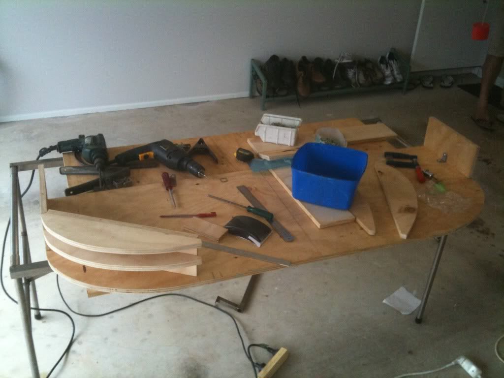
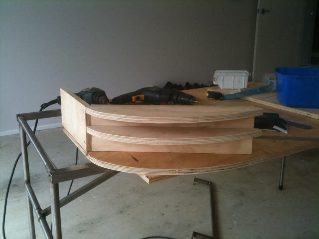
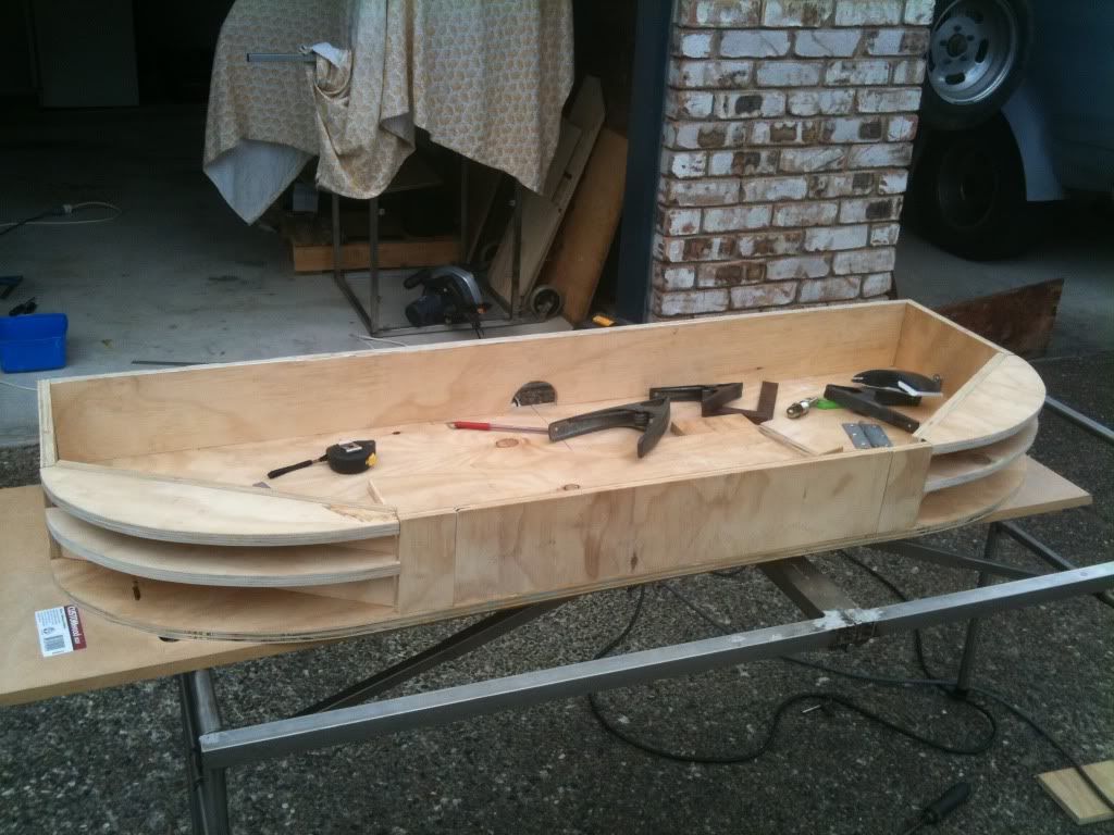
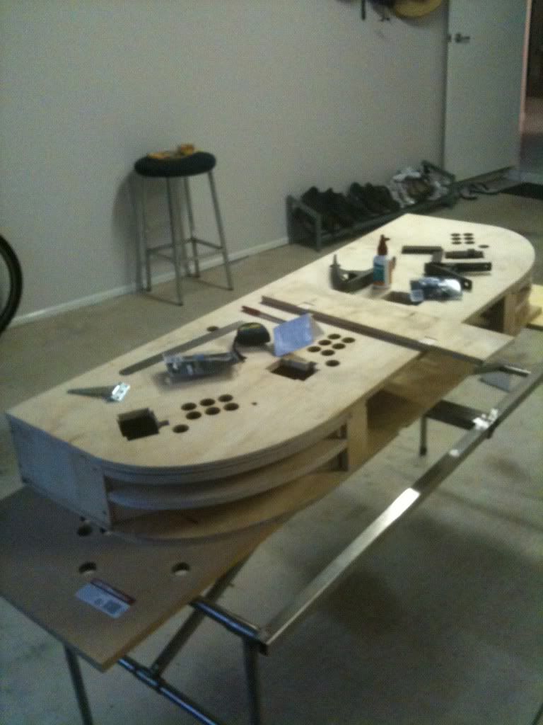
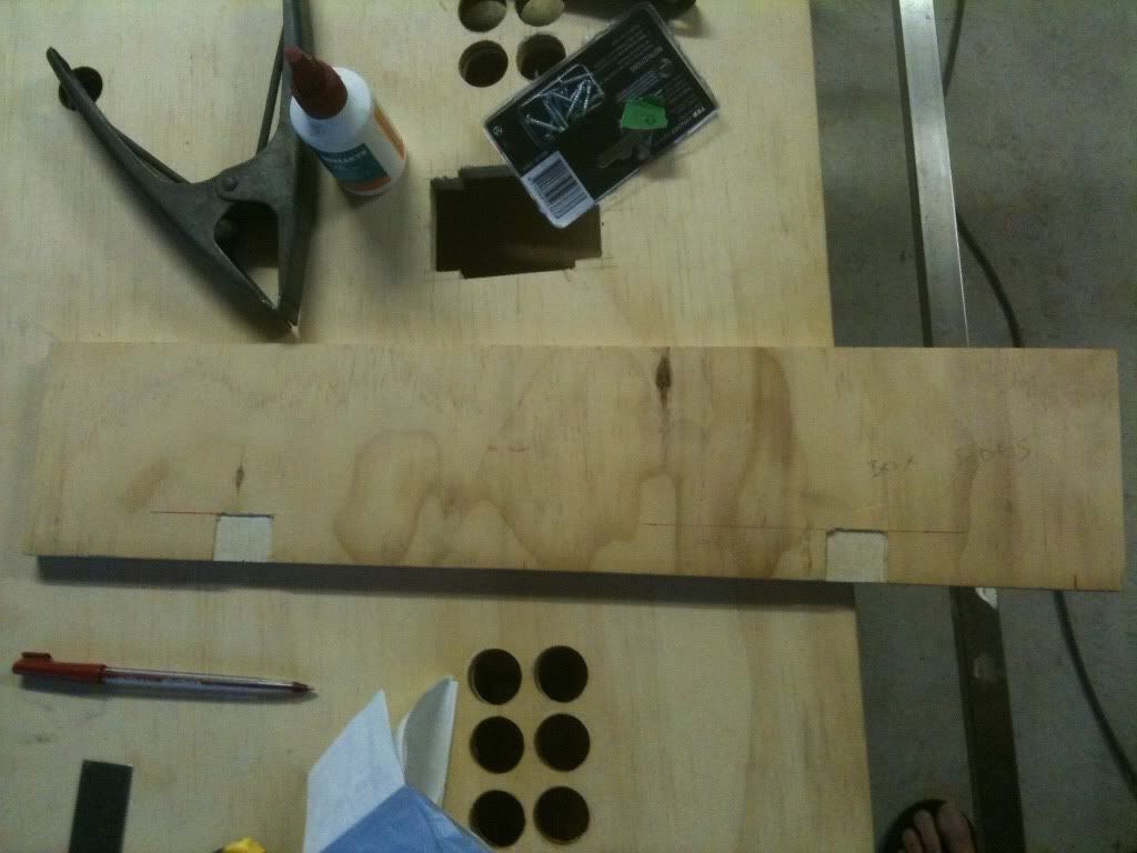
Construction of the box for the control panel involved making a plywood copy of the control panel top for the base. The design called for an en-bloc approach to the box. This meant that I didnt want overhanging wood, sharp edges or unnessecary angles. The solution was to keep the sides continuous with the top/bottom. This was achieved easily with the straight edges, but the curves would prove to be a little more tricky. It was decided to bridge the curve with more 16mm ply and add curved ribs, then cover with some sheet metal. The base provided one rib with its natural curve, so I added one at the top to support the control panel, and one in the middle to support the sheetmetal and prevent stray knees/overexcited players from putting dents in it. All were fixed with internal right-angle brackets, with longer wood screws used to join the side pieces directly to each other. The ribs needed multiple sandings to make them flush with each other once sheetmetal was laid over.
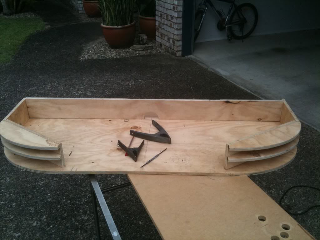
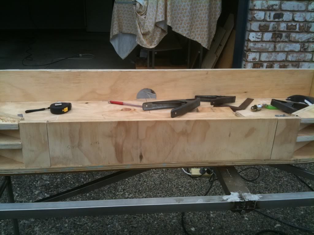
The back part of the box had a semicircular hole put in it with a hole-saw to accomdate cords. I went for the arch rather than a full hole to maintain structural support, as the control panel was going to have some weight to it and a hinge would be overlying the cord hole. Five more holes were drilled into the base of the control panel box two in-line with the stainless arms below the box to allow bolts to be passed through so that the whole control panel could be removable; two to accomodate the Top Gun cords to pass through to the underside of the box; and one with a routered underside to position the on/off switch for the whole unit. I added some plywood struts at the front to ensure a flat finish which would then accomodate a hinge-mounted drop door to give access to a draw with keyboard/mouse.
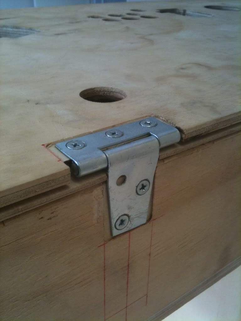
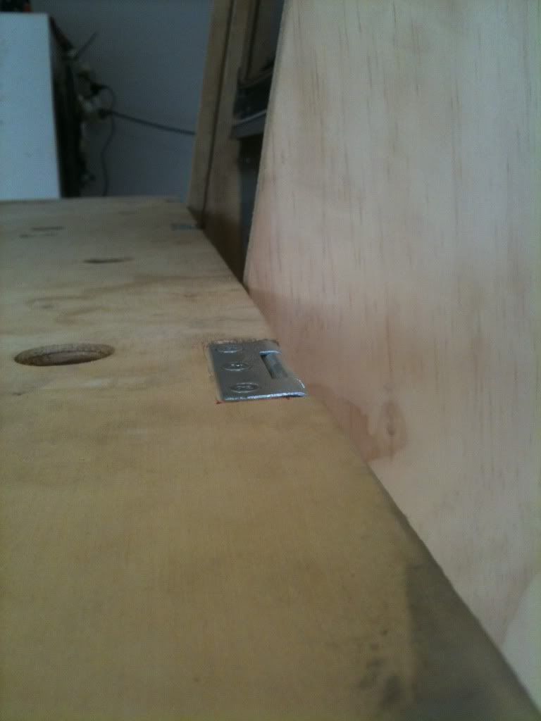
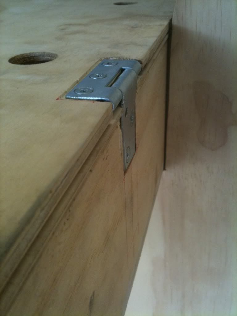
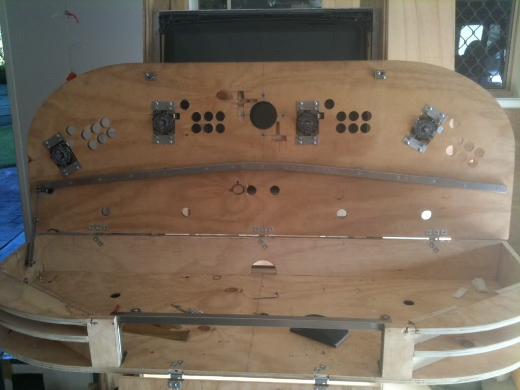
For the hinges, I trimmed them to as small as possible and routered troughs for them to sit in, to hide them below the cp overlay and sheetmetal front. There are two hinges for the front door, and three for the control panel top.
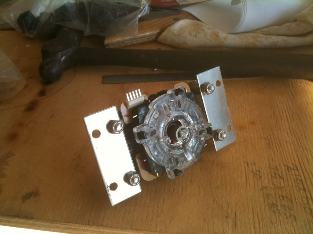
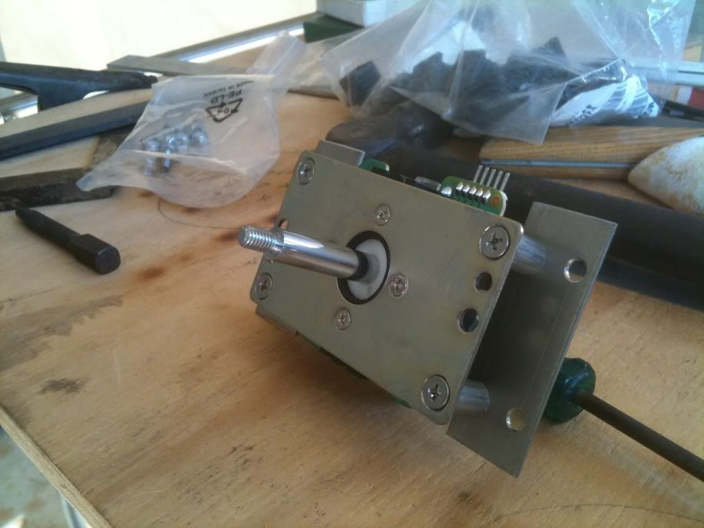
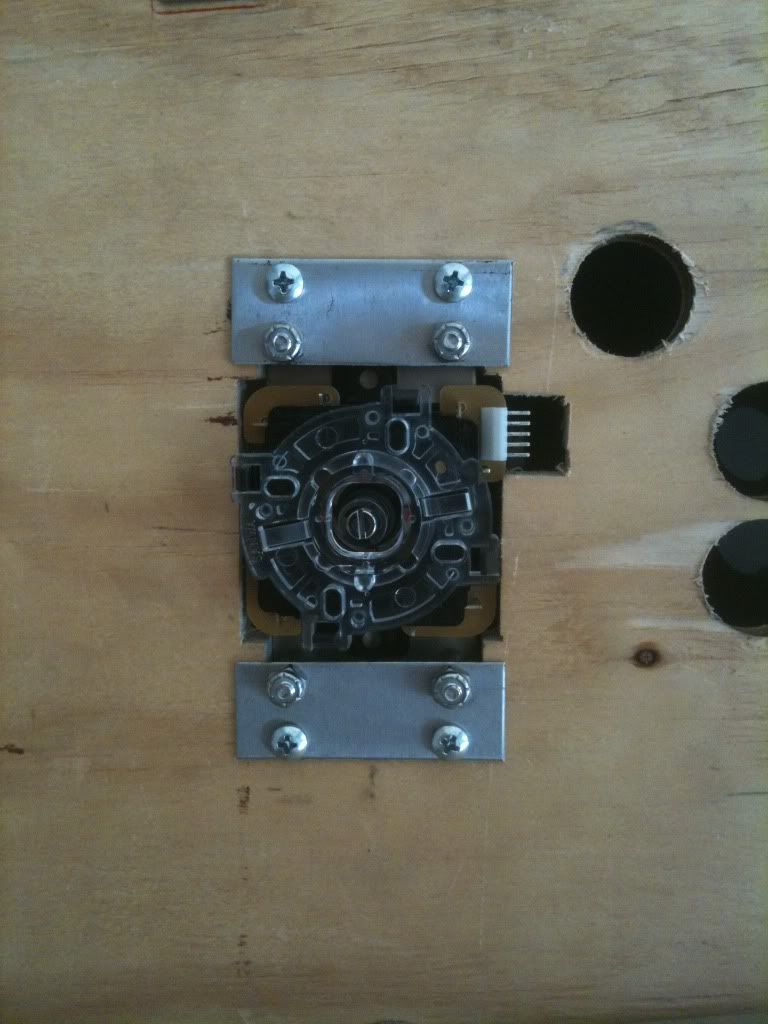
I used metal tubing spacers for the joystick mounts. I countersunk the joystick baseplate screws, bridged the depth of the 16mm ply with the spacers and secured them to stainless plates with nyloc nuts. The stainless plates then screwed directly into the underside of the control panel.
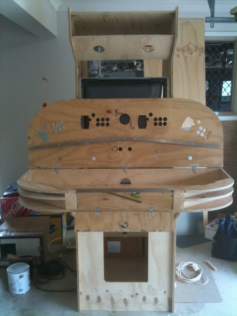
After many months of building and temperamental/humid Australian weather, the control panel top had bowed, as it was commonly free-standing up against a wall. This became evident when it was sat on top of the control panel box the lateral sides would not sit flush down against the edges. I had also toyed with the idea of ribbing the underside or placing columns between the top and the cp box base to give rigidity and support. A solution was eventually found for both - a stainless tube was screwed to the underside of the top. Two bends were placed into it for two reasons one to maximise the length/effect of the tubing, and two to allow for pushbutton/joystick/led-wiz wiring to have room on the underside. This tubing provided the rigid backbone. A process of trial and error of inserting washers between the tubing and the top (only at points where screws passed through so they wouldnt fall out) eventually got the bow straightened out. Fortunately it was a symmetrical number of washers along the length. You can also see that I used T-nuts to secure the hinges, and made a hole and routed the back of the drawer-door to allow for a camlock. There was one last piece to add before the box was a solid unit bridging the drawer-door at the front...
Since the drawer door could not be used to support the weight of the control panel above it AND function as an access, a bridge was needed. Again, stainless tubing was used. It was simply a doorframe which took the weight of the control panel above and provided a nice flush recess for the drawer door. The ply struts at the front were simply screwed onto it from within, and tabs were welded to the bottom of it to screw it to the base. This now completed the boxing of the control panel interior. We used a grinder to cut a trench into the tubing to allow for the locking arm of the camlock.

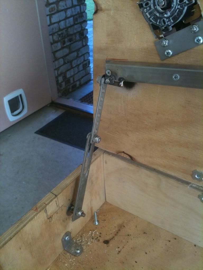
One last practical addition was to add a locking arm to the control panel top so that it wouldnt have to be held open.
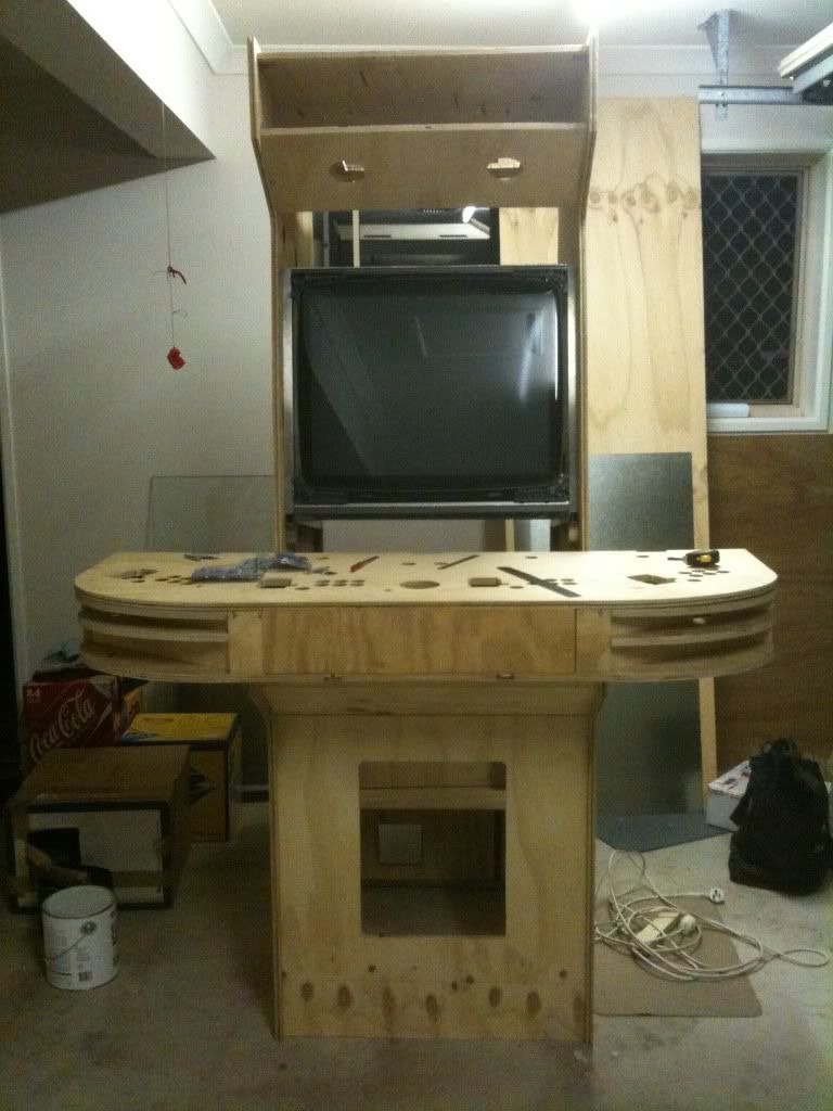
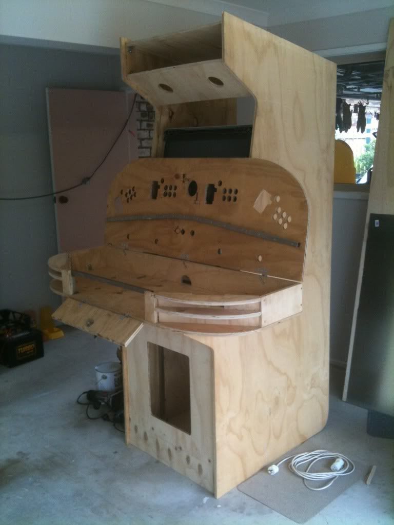
 CABINET
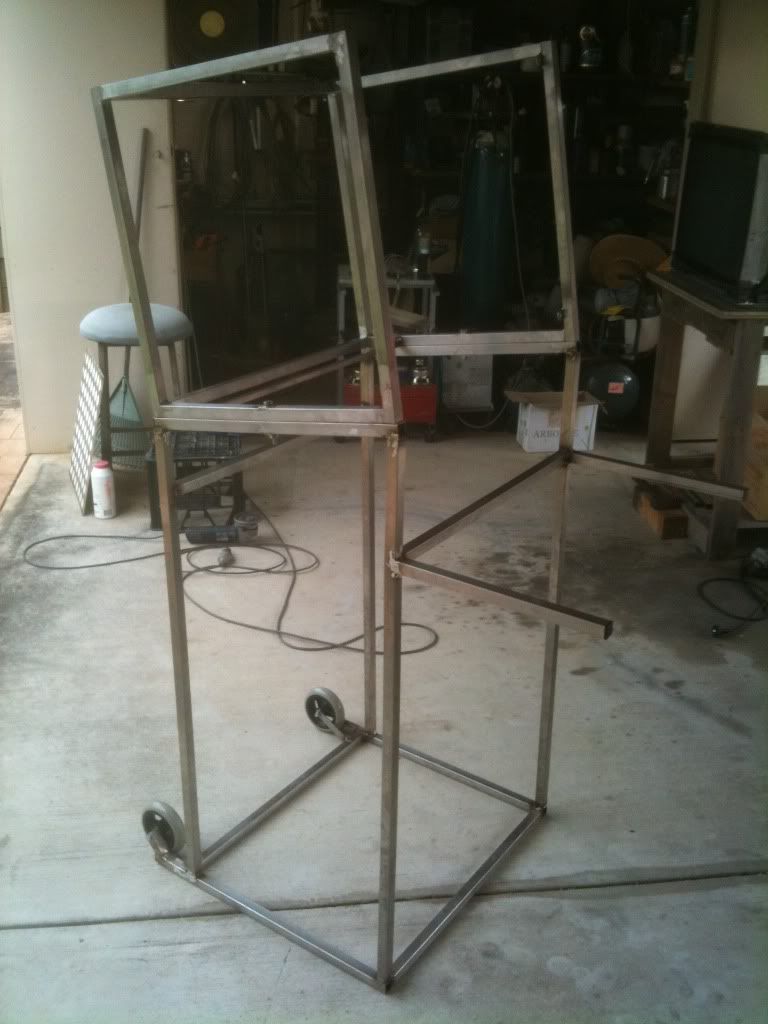
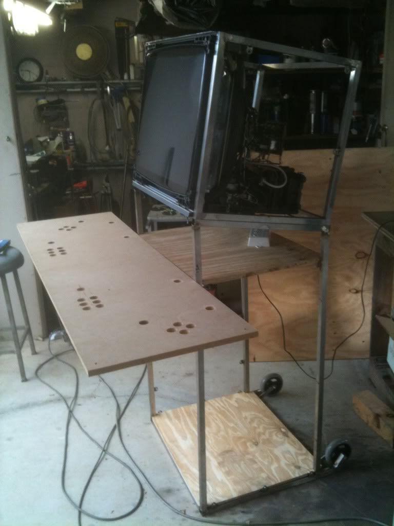
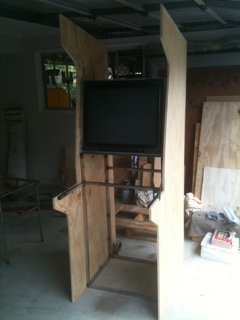
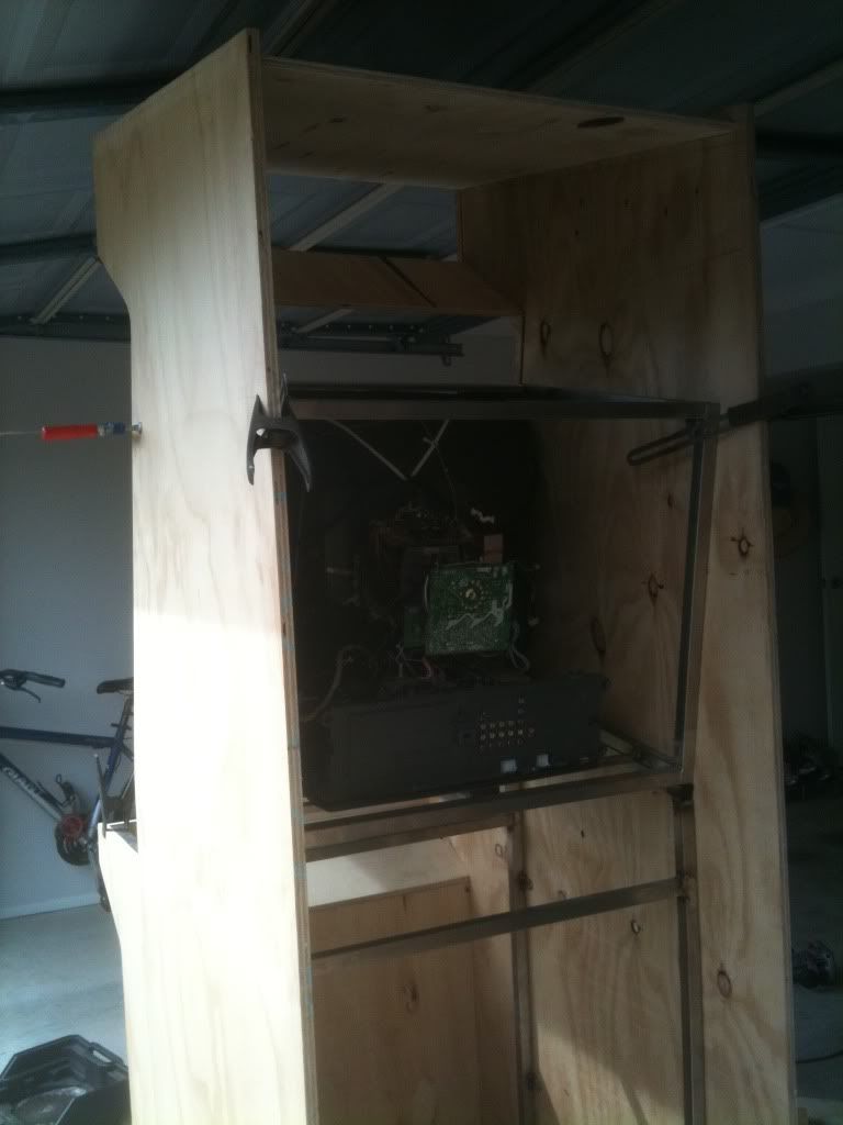
The cabinet itself, as described earlier, would see the boxed monitor sitting atop a stainless steel tube frame, which would then have the exterior simply added to it. The internal frame would provide weight-bearing duties for the whole cabinet, especially that very, very heavy monitor. The monitor was already boxed so the frame would have to provide the 10 degrees of tilt for the screen. The monitor box is actually removable - there are 4 pins at each corner of the steel frame (lower section) which fit into 4 holes drilled into the underside of the monitor box tubing. This ensures proper alignment. There are then two bolts that secure the union between lower section and monitor box, one on each side.
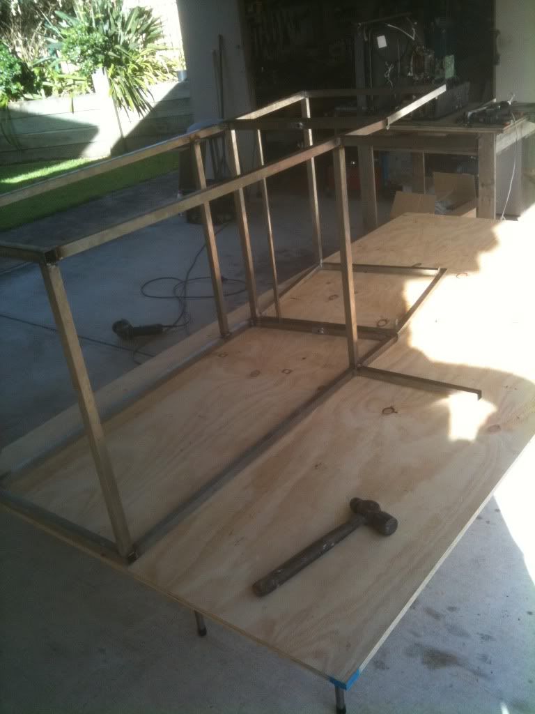
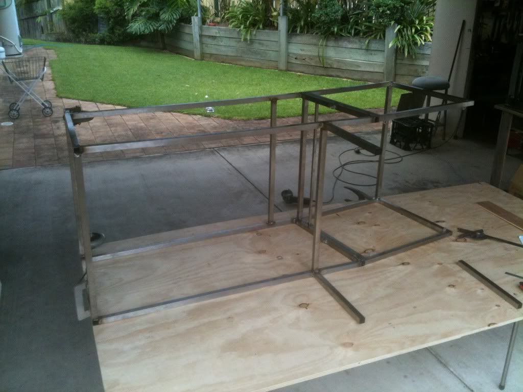
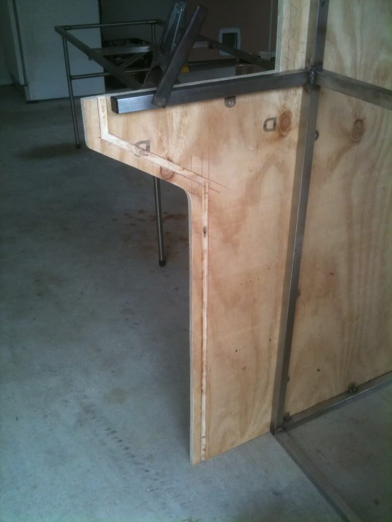
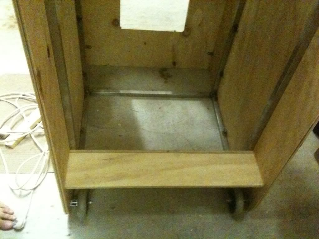
Feet were added to the rear of the frame so that wheels could be fixed and also to support the rear from tipping. Some arms were welded to the front at the pre-determined height of the bottom of the control panel. Even though the cabinet sides would be there, the control panel would be removable and bolt directly onto these arms.

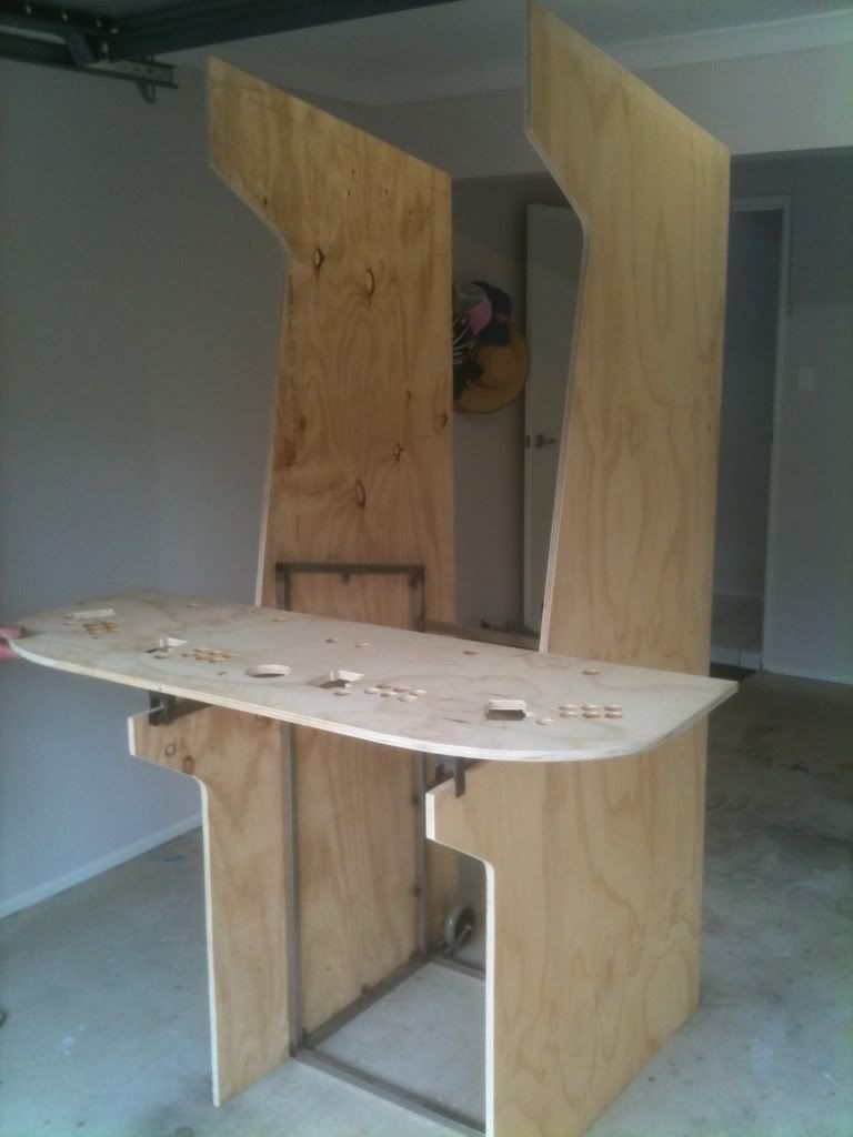
Stainless tabs with screwholes were welded along both lateral sides of the frame so that the plywood side panels could be screwed directly onto it. The side panels sit level on the ground with the frame, but serve no weight-bearing function at all. Early in the build I used the practice control panel to determine optimal dimensions and heights.
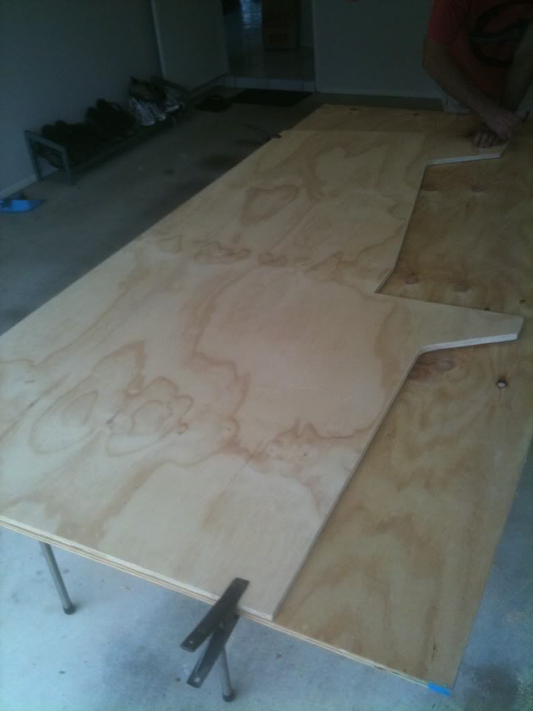
The frame dimesions were measured up alongside large sheets of 16mm of ply so that dimensions for the side panels could be thought up and drawn up.
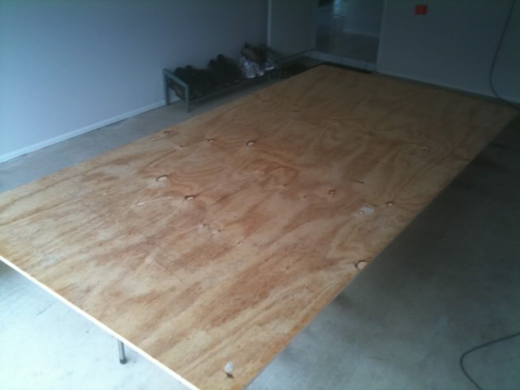
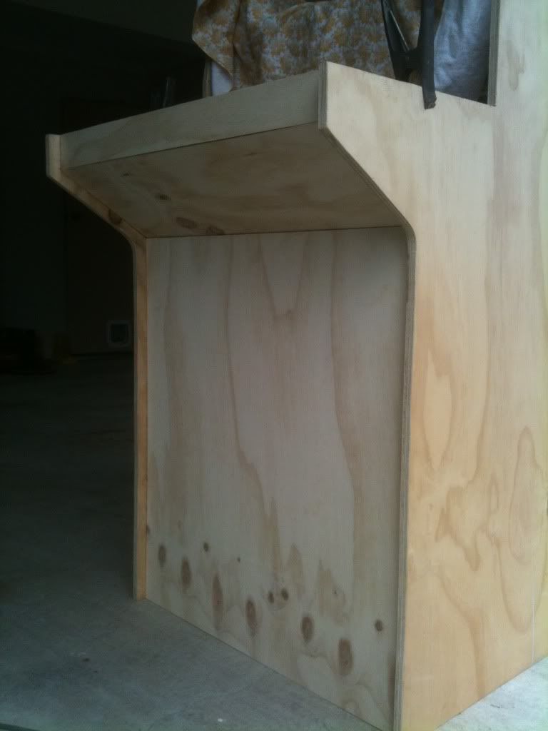
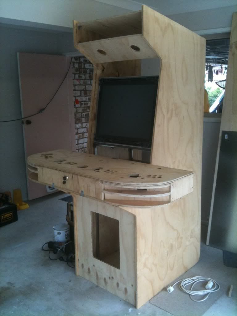
Generally, the side panels are similar in profile to a UAII cabinet if the sides were a single piece. The top of the side panels were loosely based on the Midway cabinets used for Mortal Kombat, NBA Jam etc. It was decided to follow the lead of the UAII design for the front, and recess the bottom of the cabinet and have angled bracing extend forward to assist with supporting the control panel. The angle of this cp support and the the ceiling of the cabinet to the ground are the same (parallel), and the screen was positioned at an equal distance from the top of the control panel to the start of the speaker panel above. The sides were marked and jigsawed out. Curves were made at the bottom rear to allow for the wheels to function.
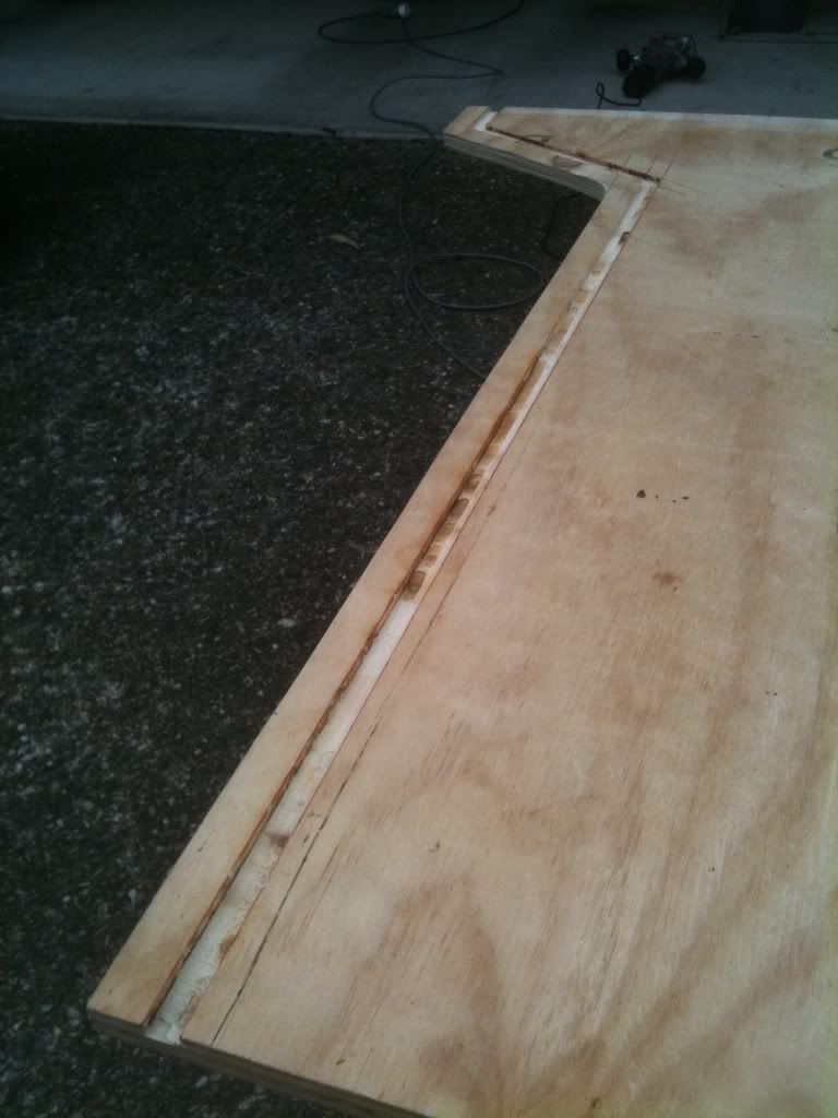
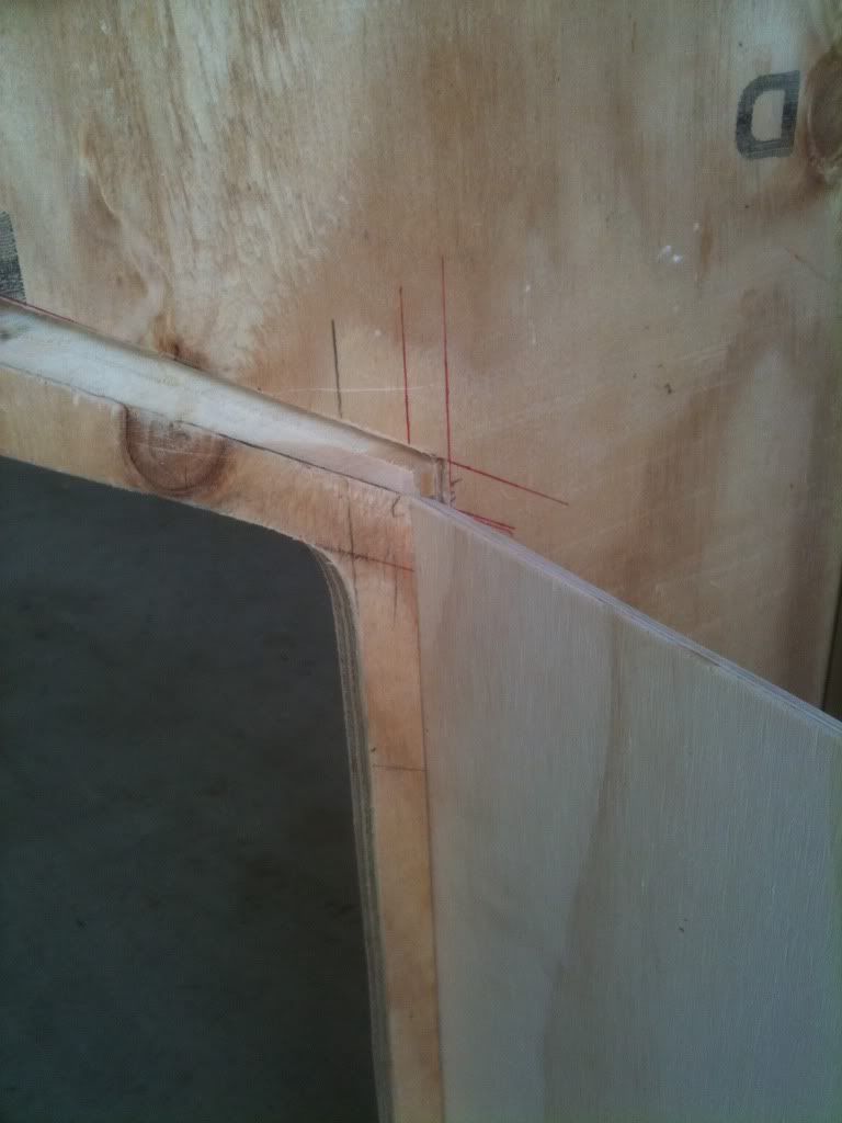
It was decided that all visible panels adjacent to the side panels would be recessed into a slot. This was for a few reasons. One, it maintained the minimalistic approach to visible fixation of the cabinet, as it could be hidden internally. Two, I didnt want to simply butt-join the panels as I thought it would leave them prone to gaps and exaggerate inconsistencies with cutting. Three, the panels would have self-adhesive vinyl coverings and these would look seemless if the front panels were slotted into a trench. Four, it kept all panels consistent with the intention of slotting the bezel and marquee. Essentially, and I think this was the best way to approach the design and building of the cabinet, any imperfections in the cabinet would end up being hidden. So slots were created with a router to accomodate 12mm plywood (cheaper [free], lighter and actually a nicer quality finish than the 16mm ply used for the sides and control panel) at a depth of 20mm from the leading edges of the side panels.
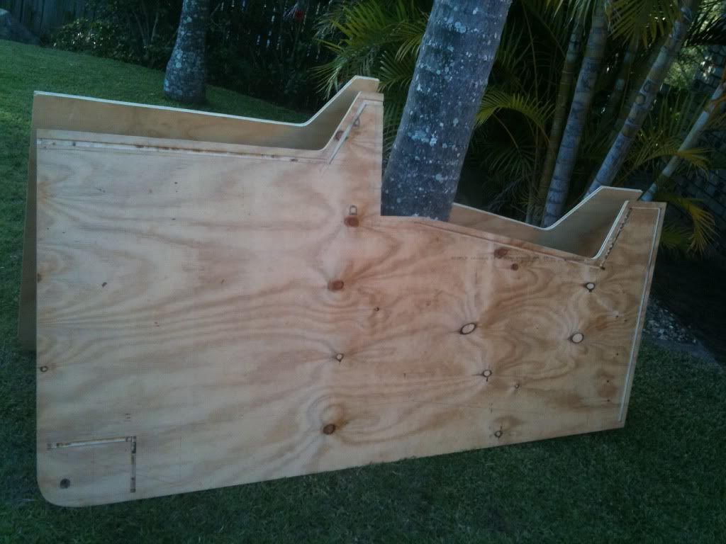
Recessed panels would include kickplate, two pieces for the control panel support, bezel, speaker panel, marquee, ceiling, and bottom-rear pieces of the cabinet. I also used the router to make circular impressions at the rear to acommodate the boltheads of the wheels. It was now a matter of beginning to assemble the cabinet.
I had deliberately not measured and cut the other panel pieces yet as I would wait and see what the measurements required would be once it was starting to be assembled. This allowed me room for error, adjustments to design (many intentions for design and changes were made along the way with this project) and angled cuts needed to help slot pieces together.
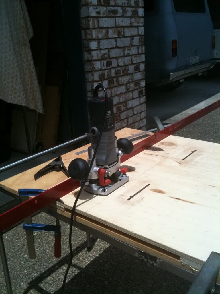
Now each panel just had to be measured, cut and put into place. I used a circular saw with a clamped guiderail to cut these pieces as their straight-lines were a little more important than the t-molded hidden edges of the side-panels.
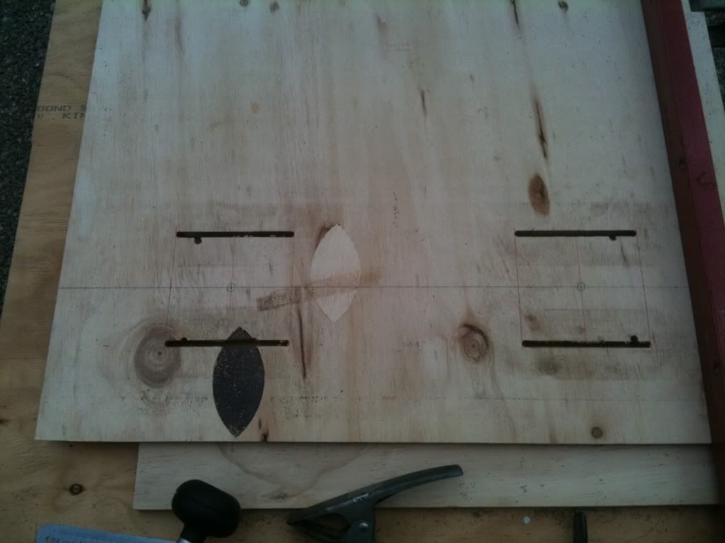
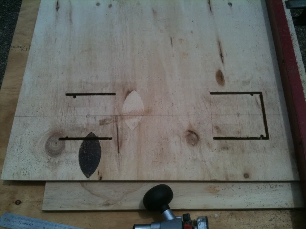
The ceiling panel had two square holes cut into it to allow for cooling fans. I used the router to do this as the curve on the router tip nicely accomodated the curved corners of the fans. To ensure straight cuts/routing, I again used a guide rail clamped into position.

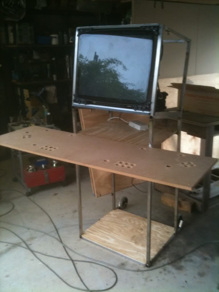
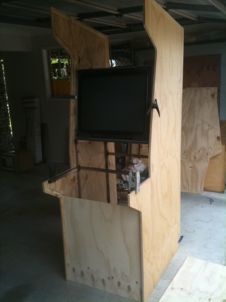
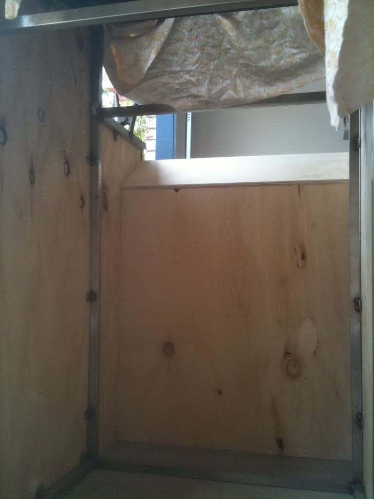
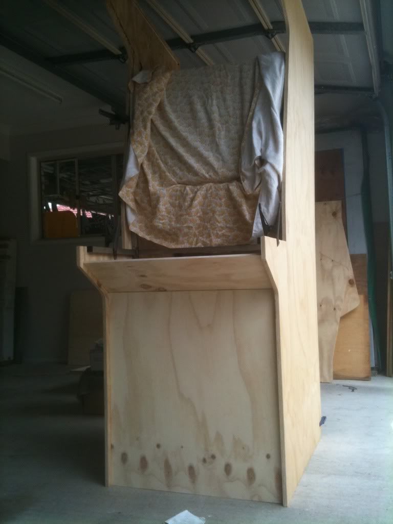
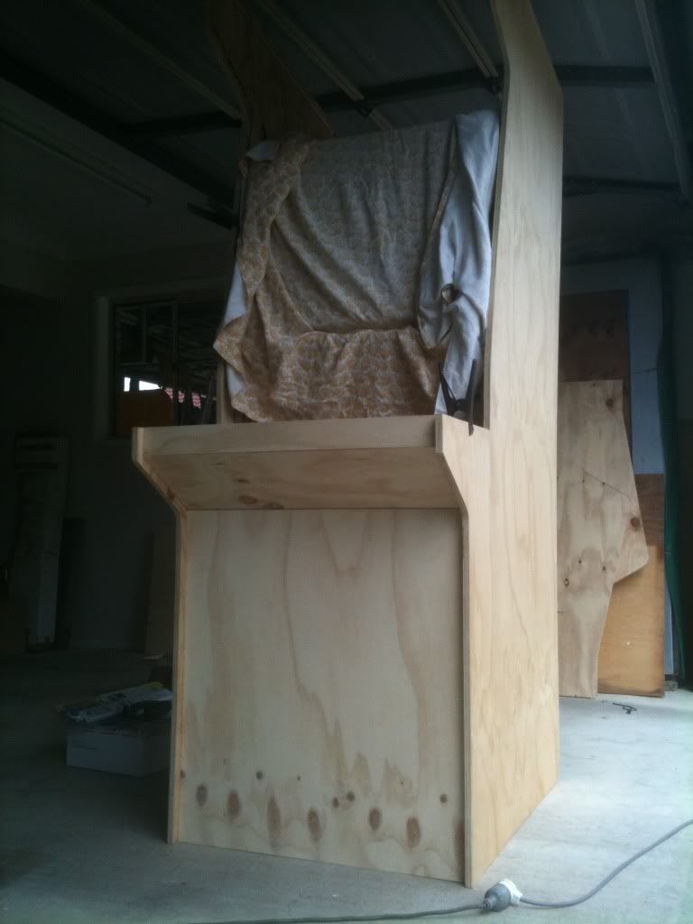
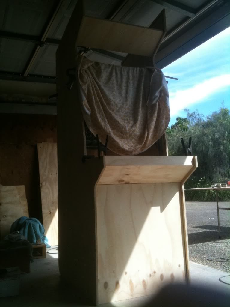
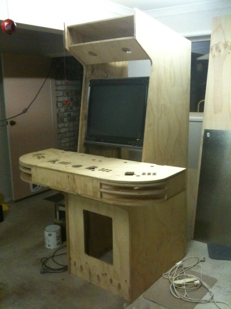
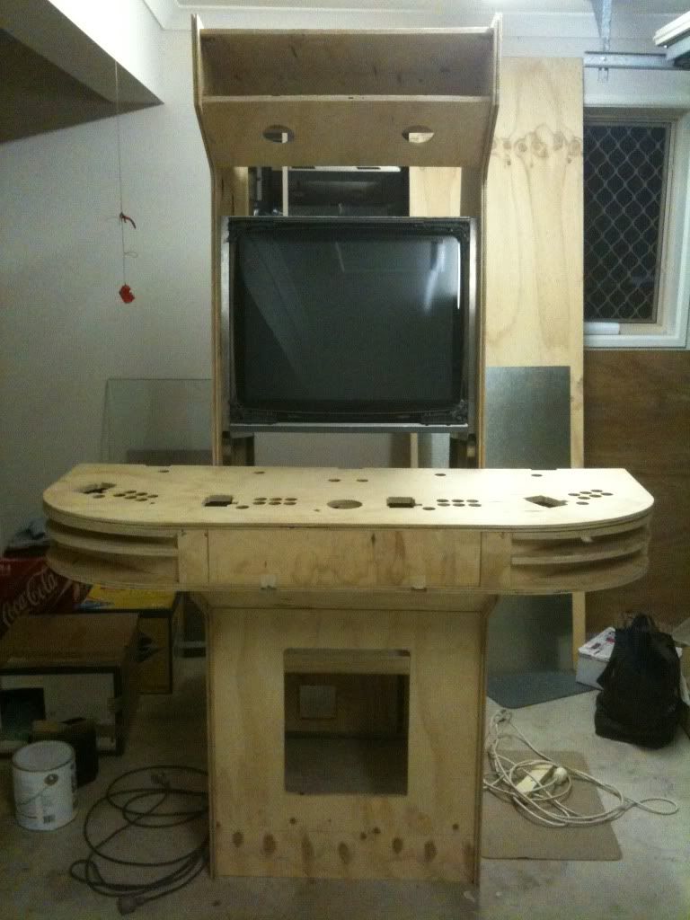
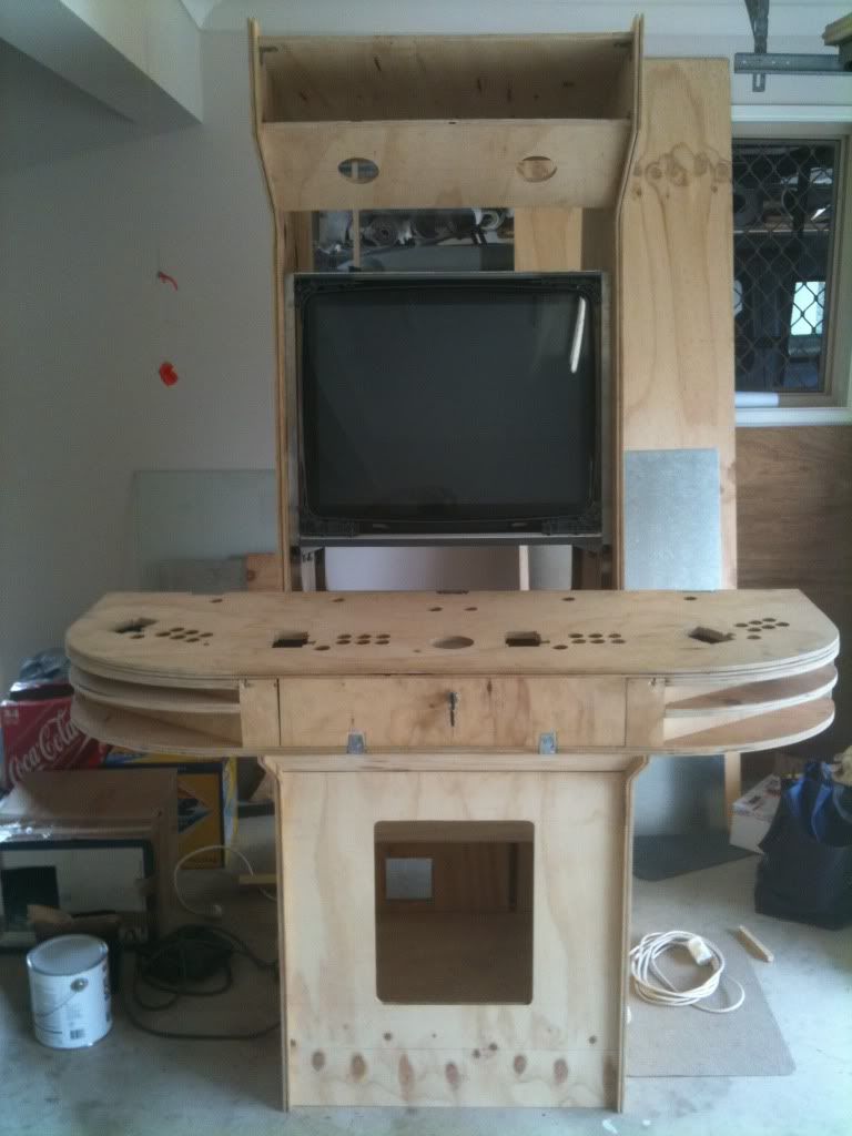
As this was a very dynamic process, I was continuously adding and removing pieces and panels to envision how things would look and what my next step would be. Here I added the control panel top (at approximate height) to see how it was a looking as a whole. Note that at this stage I had not actually started construction of the control panel box.
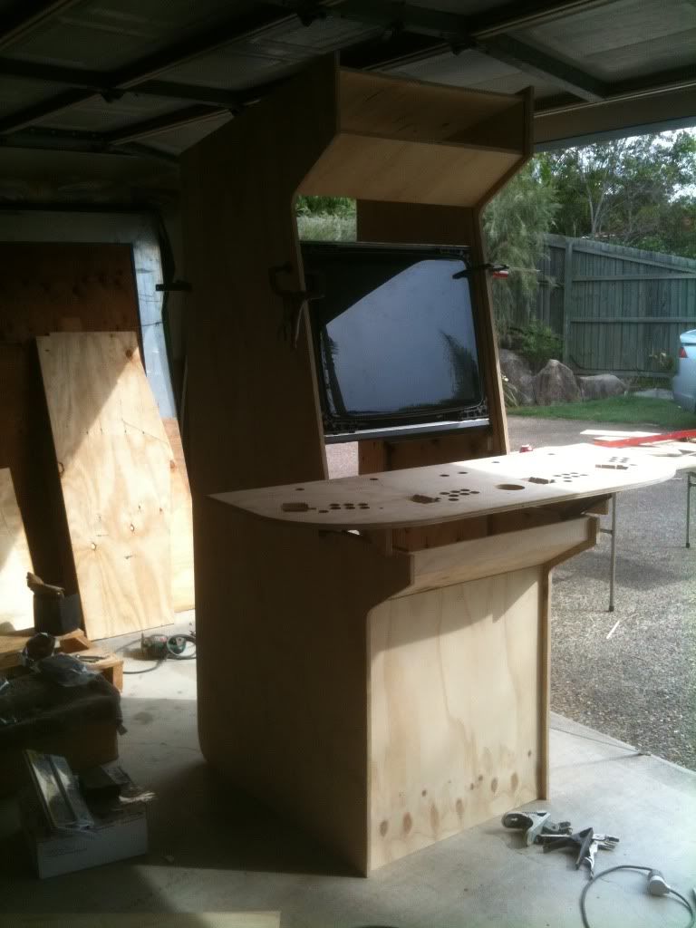
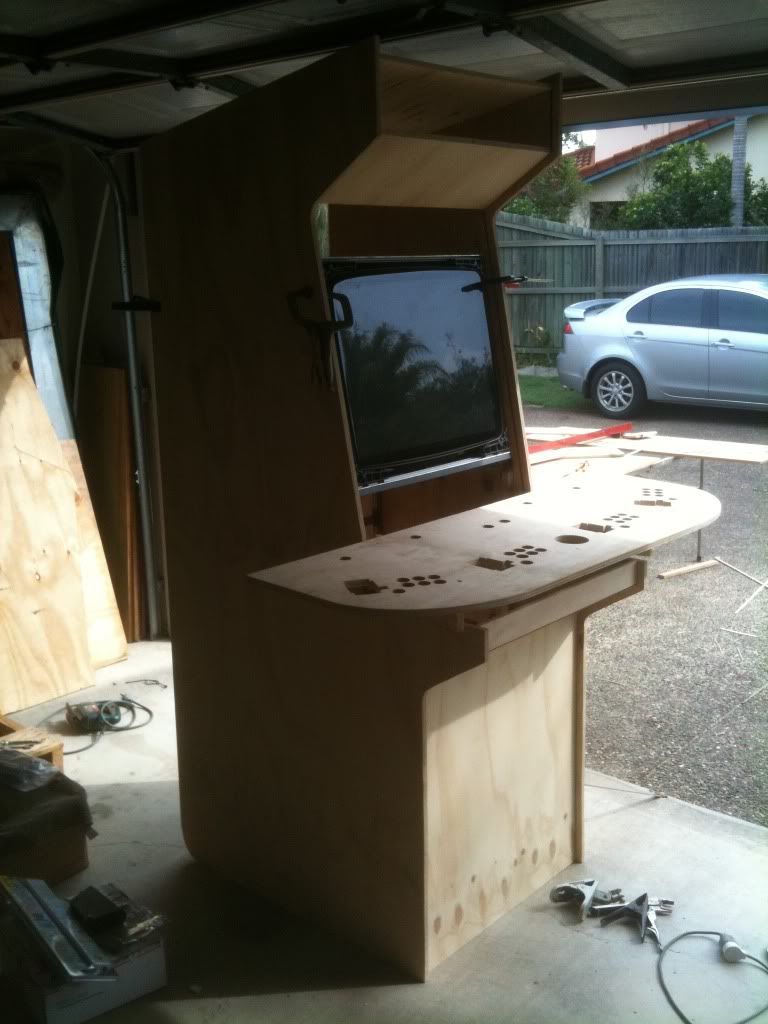
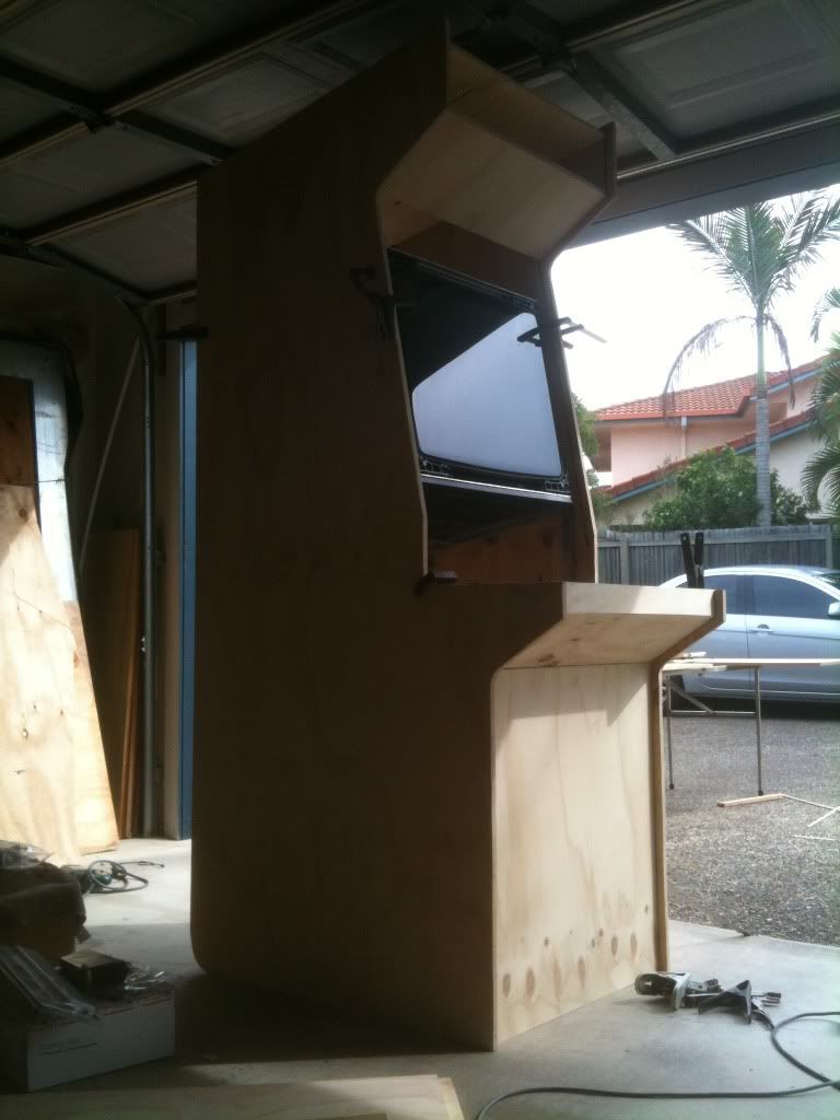
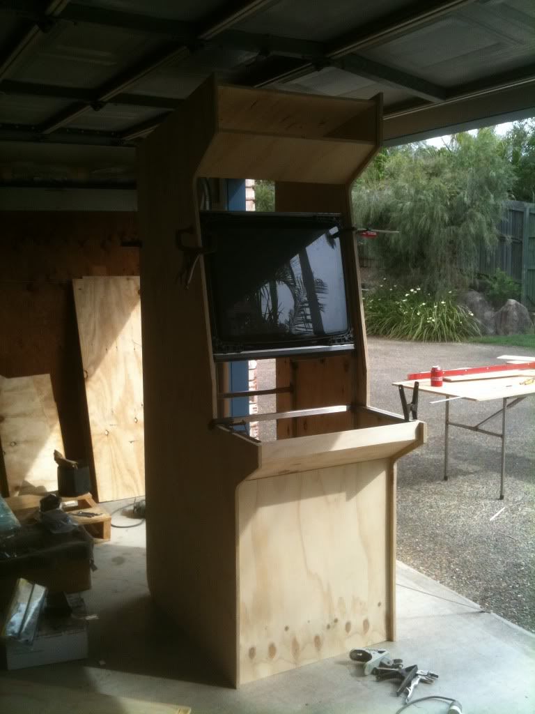
Clamps were used to hold it together prior to pre-assembly. Fixing with screws would come once all pieces were made. The hole-saw I used to cut the trackball was actually the same size I needed for the speaker panel. You find co-incidences like this along the way, and in this instance it was another simple solution. The speaker panel allows directly for the Logitec speaker cone sitting behind it. This panel is very unassuming, there is a LOT of power behind it. I also jigsawed out the hole for the coin door. I actually didnt have the coin door with me at this stage (it was still on-route) but I found dimensions for it online and took the plunge of cutting without having it with me. Fortunately this was a gamble that worked out alright (I cut inside the lines and ended up having to sand it out to make it bigger later on). I only did this because I was desperate to begin painting and didnt want to move onto that step until I had all parts/panels ready to go. Note that the actual viewing area of the screen is equal distance from the control panel below and speaker panel above symmetry!
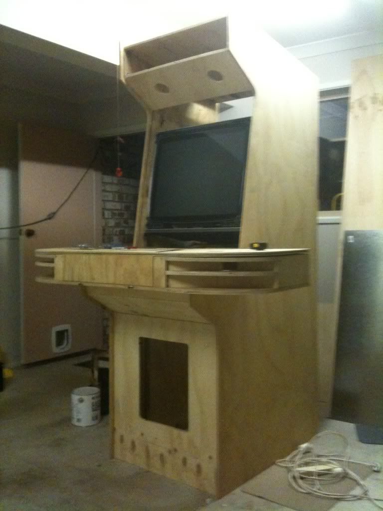

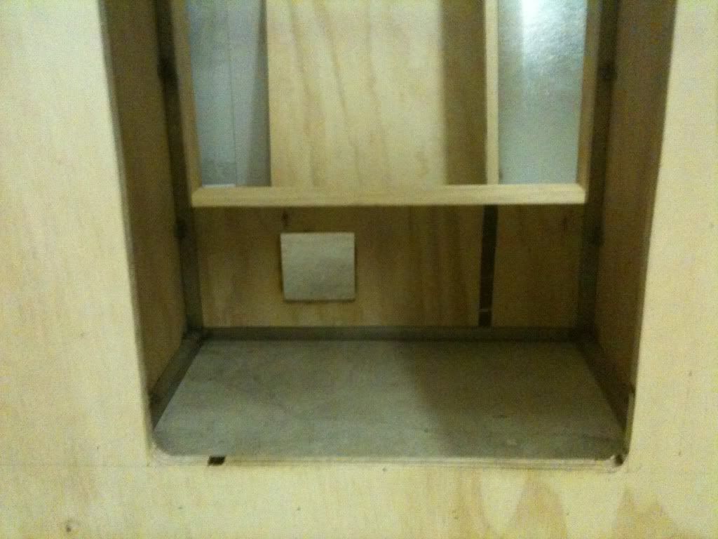
A hole was placed at the rear of the cabinet to accomodate another fan. There would be three fans in total one at the bottom with a filter drawing air into the cabinet, and two in the ceiling exhausting air out of the cabinet. As hot air rises, this ensures that cool air enters the bottom of the cabinet and is drawn upwards past the computer and monitor and exits through the top.
As different aspects of the build were occuring simultaneously, it is possible to see here that the drawer-door camlock, hinges and presumably internal structure of the control panel was constructed only after much of the cabinet itself was already complete.
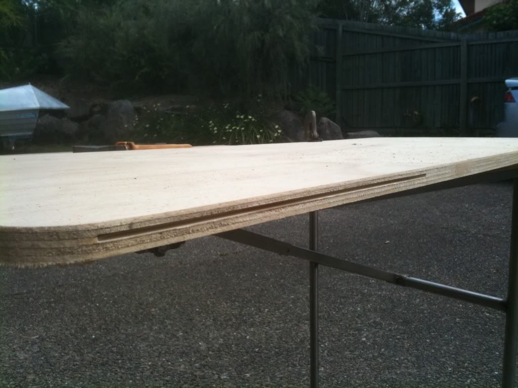
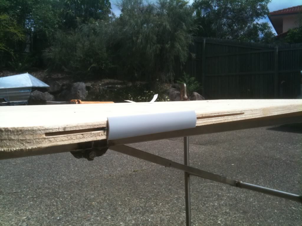
I was unable to find an appropriate sized t-molding slot cutter at the hardware store (Bunnings). The smallest they had was a 3mm cutter. I was too impatient to wait for the right sized cutter to come from elsewhere so I decided to use the 3mm cutter and offset it from center. The spine of the t-molding sat towards the middle of the edge of the ply, and the other part of the slot was wedged with a thin strip of plastic and woodglue. Thankfully measurements were correct, and a nice t-mold edge was produced with equal overhang on each side.
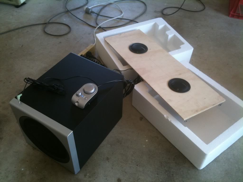
A testing session with the speakers attached to the speaker panel was necessary to observe for vibration/unwanted sound. A small amount of foam lining was placed between the speaker casing and the speaker panel to avoid this. A rear image of the speaker panel is shown later.


 Home
Home Help
Help Search
 Login
Login Register

 Send this topic
 Print
Print Topic: YIPEE KI YAY MF - 4-Player Upright Cabinet (Read 18506 times)


