Main Restorations Software Audio/Jukebox/MP3 Everything Else Buy/Sell/Trade
Project Announcements Monitor/Video GroovyMAME Merit/JVL Touchscreen Meet Up Retail Vendors
Driving & Racing Woodworking Software Support Forums Consoles Project Arcade Reviews
Automated Projects Artwork Frontend Support Forums Pinball Forum Discussion Old Boards
Raspberry Pi & Dev Board controls.dat Linux Miscellaneous Arcade Wiki Discussion Old Archives
Lightguns Arcade1Up Try the site in https mode Site News

Unread posts | New Replies | Recent posts | Rules | Chatroom | Wiki | File Repository | RSS | Submit news


Author Topic: I have GroovyMAME running on an Arcade Legends 3 Machine, do I need a J-PAC?  (Read 16395 times)

0 Members and 1 Guest are viewing this topic.

sylar

  • Trade Count: (0)
  • Full Member
  • ***
  • Offline Offline
  • Posts: 15
  • Last login:November 19, 2022, 03:03:08 pm
  • I want to build my own arcade controls!
...the OS can't see joystick/button input.

Out of the box, the Arcade Legends 3 is a PC running an Asus AT3IONT-I motherboard that boots from a USB Stick running FreeBSD. Take the USB stick out, and it becomes a normal PC. There's also a JAMMA board with an FT232 serial to USB converter. The sticks, buttons, and trackball are all wired into a JAMMA harness that the board connects into.

My main issue is that GroovyMAME cannot see these controls. It does see the FT232 at /dev/ttyUSB0, but when I screen it it's all garbage no matter what baud rate I choose. The board is chatty as well, constantly pinging the trackball for status.

What would you do if you were me? The JAMMA board is a Hanaho UA3IO (or UA310) board. This board appears to be standard JAMMA, but there is no VGA out. The Arcade Legends 3 software and ROMs are all on the USB stick, but the sound is wired from the PC board to the JAMMA board, which seems strange to me.

All help is appreciated!

Pictures and references attached.


krick

  • Trade Count: (+1)
  • Full Member
  • ***
  • Offline Offline
  • Posts: 2006
  • Last login:May 23, 2025, 03:48:36 am
  • Gotta have blue hair.
I'm pretty sure a J-PAC would work for the buttons and sticks based on the wiring schematic PDF.  Buttons 1 through 4, the stick, and START for each player go through the JAMMA connection.  Buttons 5 and 6 for each player are in that separate connector.  I'm not sure about how to get the trackball working.  Does it have a USB interface?

If its not a completely standard PC, you may want to consider removing the Arcade Legends 3 board completely and replacing it with a standard PC running Windows or Linux, whichever you're more comfortable with.  You could put the original PC away in case you want to restore the game back to its original state.

Whatever you do, do NOT hack up the original wiring harness.  Find the correct connectors and make adapter harnesses as needed to connect things.  It's a bit more work, but it's the right thing to do.  Don't be "that guy".

Bob Roberts probably has just about any connector you could want...   http://www.therealbobroberts.net/
Hantarex Polo 15KHz
Sapphire Radeon HD 7750 2GB (GCN)
GroovyMAME 0.197.017h_d3d9ex
CRT Emudriver & CRT Tools 2.0 beta 13 (Crimson 16.2.1 for GCN cards)
Windows 7 Home Premium 64-bit
Intel Core i7-4790K @ 4.8GHz
ASUS Z87M-PLUS Motherboard

sylar

  • Trade Count: (0)
  • Full Member
  • ***
  • Offline Offline
  • Posts: 15
  • Last login:November 19, 2022, 03:03:08 pm
  • I want to build my own arcade controls!
Thanks so much! I'll order a J-PAC and report back here.

sylar

  • Trade Count: (0)
  • Full Member
  • ***
  • Offline Offline
  • Posts: 15
  • Last login:November 19, 2022, 03:03:08 pm
  • I want to build my own arcade controls!
As promised, I'm posting my update here.

I received the J-PAC yesterday and it appeared to work! I haven't gotten a lot of time to mess with things but it seemed like without any customization, the joystick and buttons worked, though there wasn't an insert coin button mapping.

So that leaves what didn't work. As expected, player one buttons five and six were not working, as well as the trackball. But the surprising thing to me was that now I'm not getting sound. The way they wired things was they had the sound output from the PC going to the sound input into the Hanaho JAMMA board, and I'm pretty sure they had that board powering the speakers.

That board seemed to be a combination serial converter and sound card replicator! I think they really, really didn't want people modifying this sucker for MAME.

So it seems like next I'll need to figure out sound, I'll need to rewire the interface for the trackball and buttons 5 and 6 on both controllers, and I'll need to make it so that the CRT monitor doesn't go crazy. Got my work cut out for me, it seems.

So yeah, I don't want to be THAT guy, but I may not have any other choice. Bummer, unless anyone has any other recommendations.

krick

  • Trade Count: (+1)
  • Full Member
  • ***
  • Offline Offline
  • Posts: 2006
  • Last login:May 23, 2025, 03:48:36 am
  • Gotta have blue hair.
None of this is going to be "plug and play", if that's what you were expecting.  Half of the fun of this hobby is working on the machine and figuring out solutions to problems.

That Hanaho board was probably a sound amplifier of some kind.
You probably need to rig up a cheap amplifier to drive the speakers.

I used what's called a "PC speaker hack" in my cabinet...
http://forum.arcadecontrols.com/index.php?topic=16381.0
http://mame.3feetunder.com/pcspeakerhack/

You can google and find lots of other similar setups.

If you look at your wiring diagram PDF, in the middle of the page, near the top, there's a 9-pin connector for the speakers.  If you get the correct connector, you should be able to wire up a PC speaker hack and plug it directly into the 9-pin connector in the harness.

As for the other buttons that aren't working, check out this JAMMA pinout on the J-PAC page...
http://www.ultimarc.com/jpac2.html

There doesn't seem to be a coin door.  How did you add credits to the game originally?  Was there a dedicated coin button somewhere?

Buttons five and six can be wired into the extra screw terminals on the J-PAC but like I said before, resist the urge to cut the wiring harness.  If you trace the wiring from buttons 5 and 6 for each player, it should end in a connector that was plugged in to the old board.  Get the correct connector to mate up with that connector and then wire from that new connector to the J-PAC screw terminals.

As for the trackball, follow the wiring from the trackball and see where it goes.  Trackballs basically have two interfaces.  Older trackballs had optical sensor boards that connected to some kind of encoder that fed the signals into the game board through (usually) proprietary connectors.  Newer trackballs have USB interfaces and plug into the game board via a USB plug.  Try to figure out what you have and then go from there.  I'm betting it's USB but it's possible that it's not to force people to buy repair parts from them.
Hantarex Polo 15KHz
Sapphire Radeon HD 7750 2GB (GCN)
GroovyMAME 0.197.017h_d3d9ex
CRT Emudriver & CRT Tools 2.0 beta 13 (Crimson 16.2.1 for GCN cards)
Windows 7 Home Premium 64-bit
Intel Core i7-4790K @ 4.8GHz
ASUS Z87M-PLUS Motherboard

sylar

  • Trade Count: (0)
  • Full Member
  • ***
  • Offline Offline
  • Posts: 15
  • Last login:November 19, 2022, 03:03:08 pm
  • I want to build my own arcade controls!
Krick -- I know none of this is going to be plug and play. I was hoping for a more straightforward approach since the guts of the AL3 appeared to be a standard PC. The custom JAMMA card they used seems unnecessary.

I know very, very little about wiring. I understand the concepts though. I do have the ProjectArcade book, so that's a start.

I noticed in the J-PAC link you sent that to get an insert coin have to press the 1 player button along with button1 player 1. So that's awesome. The AL3 games were on free play and thus there was no insert coin button.

The AL3 does have a button behind the insert coin door that was intended to get into diagnostics and allow the user to correct overscan and set the volume.

I've attached a pic of the connector for the trackball and the extra P1 wires. Since I am so new, I have no idea what to even google search for as far as connecting this guys to the J-PAC. Same with the speaker 9 pin thing. Got any advice?

I've also attached a pic of the Hanaho JAMMA board. Pity there seem to be no public drivers for this thing, as then this would have been very close to plug and play. At least I get to learn a few things! Thanks for teaching.
 

Malenko

  • KNEEL BEFORE ZODlenko!
  • Trade Count: (+58)
  • Full Member
  • ***
  • Offline Offline
  • Posts: 14019
  • Last login:Today at 06:33:34 pm
  • Have you played with my GingerBalls?
    • forum.arcadecontrols.com/index.php/topic,142404.msg1475162.html
wanna get rid of the AL stuffs?
If you're replying to a troll you are part of the problem.
I also need to follow this advice. Ignore or report, don't reply.

krick

  • Trade Count: (+1)
  • Full Member
  • ***
  • Offline Offline
  • Posts: 2006
  • Last login:May 23, 2025, 03:48:36 am
  • Gotta have blue hair.
I've attached a pic of the connector for the trackball and the extra P1 wires. Since I am so new, I have no idea what to even google search for as far as connecting this guys to the J-PAC. Same with the speaker 9 pin thing. Got any advice?


The trackball cannot connect to the J-PAC.  The JAMMA standard only includes joysticks and buttons.

From what I see, I think the trackball is probably a standard (non USB) trackball.  If that is the case, then you can use a standard optical encoder interface to connect it to your PC...

Opti-Wiz (you want the no-solder version)
http://groovygamegear.com/webstore/index.php?main_page=product_info&products_id=260

Opti-PAC...
http://www.ultimarc.com/optipac1.html

You have to do some detective work to figure out which wires go where.

Here's the part of the Arcade Legends 3 wiring schematic that shows the trackball connector...


According to the schematic, it's a 12-pin connector with .100 spacing (.100 inch spacing = 2.54mm spacing).  So what you're looking for is something like the 6-pin male connector on this cable.  I think they call them "dupont connectors".  Basically, as long as the pin spacing is the same, it should work...

..but your trackball connector is a 12-pin female.

Rather than trying to track down a 12 position connector, the male crimp pins, some wire, and a crimping tool, I'd probably try getting something like this off ebay...
http://www.ebay.com/itm/391026510847


I think you can "tear" it into strips of however many wires you need.  You can stick the male ends into the connector on your wiring harness and the other end can either stick on the pins of the Opti-Wiz or you can cut off the female connectors and use the bare wires for the Opti-PAC.


For the extra buttons (5 and 6) for each player, you can do basically the same thing.

Here's the connector from your schematic...


It has the same kind of connector, again with the .100 inch spacing.  So you can use the same type of solution as the trackball, except you don't need an extra encoder board.  The J-PAC has screw connectors for buttons 5 and 6.  So just take some of the jumper wires and plug the pin ends into the harness connector for the buttons, cut off the female ends, strip a little bit of the insulation back and connect the wires to the correct screw terminals on the J-PAC.


Lastly, here's the speaker connector on your schematic...


According to the schematic, it's a .165 inch pitch (4.14mm pitch) "AMP" connector with a 9-pin 3x3 configuration.  I don't see it anywhere in your pictures, so I'm not sure if the speaker side is male or female.

Here's someone selling the connector housings on Ebay, but they don't include the crimp-pins  (one side uses male pins, the other female pins)..
http://ebay.com/itm/111436267445

If you got these housings, you'd have to find 4.14mm AMP crimp pins of the correct gender, and a tool to crimp them.
« Last Edit: February 06, 2015, 10:00:06 am by krick »
Hantarex Polo 15KHz
Sapphire Radeon HD 7750 2GB (GCN)
GroovyMAME 0.197.017h_d3d9ex
CRT Emudriver & CRT Tools 2.0 beta 13 (Crimson 16.2.1 for GCN cards)
Windows 7 Home Premium 64-bit
Intel Core i7-4790K @ 4.8GHz
ASUS Z87M-PLUS Motherboard

sylar

  • Trade Count: (0)
  • Full Member
  • ***
  • Offline Offline
  • Posts: 15
  • Last login:November 19, 2022, 03:03:08 pm
  • I want to build my own arcade controls!
Again, Krick, you're fantastic and I appreciate all of your help.

The speaker 9-pin thing, I found it and it's in the back of the unit, that's why you can't see it in pictures. And it's connected right now, so I don't know whether I need a male or female. I'll find that out.

One thing I do know is that sound output comes from the PC Motherboard in the unit. The question is how to route the wires.

The speaker wires are connected to the JAMMA interface per the schematic, but now my J-PAC is in this interface. While the JPAC has connectors for sound wires, I am not sure if the J-PAC is doing output. It doesn't seem like it should be.

In other words, I think I need to bypass the JAMMA and J-PAC completely for output. What do you think I would need in order to do that? I'm likely back at having to read and understand the speaker hack you did, right?

krick

  • Trade Count: (+1)
  • Full Member
  • ***
  • Offline Offline
  • Posts: 2006
  • Last login:May 23, 2025, 03:48:36 am
  • Gotta have blue hair.
Back in the old days, arcade boards often had built-in sound amplifiers.

The JAMMA standard only supports a single mono speaker (two wires).  These correspond to "L" and "10" on the JAMMA connector.

Some arcade machine manufacturers use slightly non-standard JAMMA wiring in order to support stereo speakers (four wires).  So, in addition to "L" and "10", they generally use "M" and "11" on the JAMMA connector.

If you look at the Arcade Legends 3 schematic, you'll see which wires from the JAMMA connector go into that 9-pin connector that eventually goes to the speakers (and probably the marquee light as well).

In your wiring harness, there are 7 wires that go from the JAMMA connector to that 9-pin connector.  The individual "pins" on the edge connector are referenced with letters on the "solder side" and numbers on the "parts side".  These refer to the original arcade boards.

Here's the wires that go from the JAMMA connector to that 9-pin connector:

10:  Speaker+ 1
L:  Speaker- 1
11:  Speaker+ 2
M:  Speaker- 2

Not sure if speaker 1 is on the left or right.  Speaker 2 is on the other side.

F:  +12V  (probably for marquee light)
27:  Ground (also for marquee light)

R:  Service???  maybe some kind of service switch or maybe a push button to turn on the PC?

I've colored the connections so you can see what I mean.  The red circle is where the wires all come together and head over to the 9-pin connector...


The JPAC has it's own set of connections, but only certain ones are actually connected since the typical PC MAME cabinet use doesn't need them.  Here's the diagram with the 7 JAMMA pins listed above circled in green for reference.  Notice that there are only two speaker connections as per the JAMMA standard, not four.  Also note that the +12V connection is not connected either.


The takeaway here is that in order to get working speakers and whatever the +12V goes to (I assume the marquee light), you'll have to wire them up by bypassing the JPAC.

For the speakers, you need to get the line-level out sound from the motherboard's audio out jack, amplify it, and feed it to the speakers in your cabinet.  The easiest way to do this is to get a cheap pair of PC speakers and rip out the amplifier.  This is often called a "PC speaker hack".  I posted some PC speaker hack links earlier.

For the marquee, you can get +12V and ground connections from one of the 4-pin Molex connectors on the power supply.  These connectors are typically used for hard drives.  Here's a diagram.  The connector I'm talking about is in the lower left...


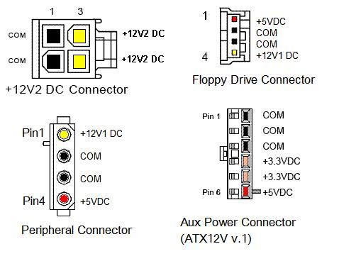
To get power from a molex connector without hacking up the wiring on your power supply, you can pick up something like this, cut off the black connector, and remove the red (+5V) wire, and one of the black (ground) wires, leaving the yellow (+12V) wire and one black (ground) wire.

« Last Edit: July 11, 2018, 01:35:31 am by krick »
Hantarex Polo 15KHz
Sapphire Radeon HD 7750 2GB (GCN)
GroovyMAME 0.197.017h_d3d9ex
CRT Emudriver & CRT Tools 2.0 beta 13 (Crimson 16.2.1 for GCN cards)
Windows 7 Home Premium 64-bit
Intel Core i7-4790K @ 4.8GHz
ASUS Z87M-PLUS Motherboard

skelt

  • Trade Count: (0)
  • Jr. Member
  • **
  • Offline Offline
  • Posts: 1
  • Last login:September 30, 2015, 01:38:54 am
  • I want to build my own arcade controls!
Re: I have GroovyMAME running on an Arcade Legends 3 Machine, do I need a J-PAC?
« Reply #10 on: September 29, 2015, 11:40:36 pm »
Got my brand new AL3 cabinet today from chicago-gaming.  Much to my dismay the power coupler to the I/O board was not properly seated and apparently damaged the board due to not getting the full 5 volts, according to tech support.  Demo mode works fine, so the cabinet just teases me.  NO controls or buttons work.  They said they are sending a new board to me to install so I may return to the knowledgeable folks here for assistance in installing.  I am an audio technician by trade so my computer tech skills are somewhat lacking.  Really looking forward to re-living the glory days of my arcade youth.  Cheers, and have fun!