Main Restorations Software Audio/Jukebox/MP3 Everything Else Buy/Sell/Trade
Project Announcements Monitor/Video GroovyMAME Merit/JVL Touchscreen Meet Up Retail Vendors
Driving & Racing Woodworking Software Support Forums Consoles Project Arcade Reviews
Automated Projects Artwork Frontend Support Forums Pinball Forum Discussion Old Boards
Raspberry Pi & Dev Board controls.dat Linux Miscellaneous Arcade Wiki Discussion Old Archives
Lightguns Arcade1Up Try the site in https mode Site News

Unread posts | New Replies | Recent posts | Rules | Chatroom | Wiki | File Repository | RSS | Submit news


Author Topic: K7000 - Single Horizontal Line after Flyback and Cap Kit Replacement  (Read 5438 times)

0 Members and 1 Guest are viewing this topic.

NoAffinity

  • Trade Count: (0)
  • Jr. Member
  • **
  • Offline Offline
  • Posts: 9
  • Last login:May 03, 2025, 08:06:23 am
Hello All,

Recently, my flyback transformer failed.  The typical failure from my understanding: a steady stream of fault current from flyback to the metal partition to the left of it (if looking into the back of the cabinet, at the flyback and video board).  The flyback fails about once a year, this time I squeezed 2 years out of it, but new it was starting to fail at the one year mark - if I turn my cabinet off after playing for a while and then back on, the video would be all garbled.  It seems to be heat related, because I could let it sit for 10 or 15 minutes, turn it back on, and all would be fine.  The "cooldown" period would have to be longer on hot days and shorter on cool days.

That aside, I replaced the flyback and capacitor kit.  The kit I had for a couple years.  When I hooked it back up, I ignorantly connected the H sync and RGB connectors backwards.  So R was on H sync ground, blue was on H sync; H sync ground was on R and H sync was on blue.  I also failed to connect the gray cable that comes off the neck board, to the one in the cabinet.  This cable surrounds the back of the monitor, and I'm guessing is a ground.

When I first turned it on, with things connected wrong as outlined above, there was no video.  There might have been a slight burning smell, but nothing persistent, nothing that I could see was on fire, and it didn't replicate once I fixed the above described mis-connections.

Now, I get what you see in the picture.  The only adjustment that makes any difference is the "focus" and "screen" controls.  The make the line slightly taller, with more color, and make it go way completely.  "Vert Hold" makes the line move up and down slightly.  All other controls do nothing.  Thoughts?  Was the initial mis-wiring the cause?  Or have I possible replace a cap (or more than one cap) with the wrong replacement(s) from the kit?  I am going to re-check all the replacements again, but would appreciate any feedback, especially if other have experienced this.
« Last Edit: June 22, 2014, 10:09:34 am by NoAffinity »

NoAffinity

  • Trade Count: (0)
  • Jr. Member
  • **
  • Offline Offline
  • Posts: 9
  • Last login:May 03, 2025, 08:06:23 am
Re: K7000 - Single Horizontal Line after Flyback and Cap Kit Replacement
« Reply #1 on: June 22, 2014, 10:36:20 am »
Upon further inspection, I found one cap that appears to not be correct.

according to a cap kit list I found online, c21 is supposed to be 10u     50V.  The one installed, however is 10u   25V.

Admittedly, I did not do the soldering, and I found some instances of solder points of the replaced caps being apparently electrically connected to solder points of surrounding transistors and/or diodes.  I also found one instance, at c46, where the legs of the cap are apparently electrically connected (see picture).

grantspain

  • I personally prefer "bog trotter"
  • Trade Count: (+1)
  • Full Member
  • ***
  • Offline Offline
  • Posts: 6177
  • Last login:July 16, 2025, 06:33:55 pm
Re: K7000 - Single Horizontal Line after Flyback and Cap Kit Replacement
« Reply #2 on: June 22, 2014, 10:51:00 am »
take a good photo of the entire solder side of the chassis


NoAffinity

  • Trade Count: (0)
  • Jr. Member
  • **
  • Offline Offline
  • Posts: 9
  • Last login:May 03, 2025, 08:06:23 am
Re: K7000 - Single Horizontal Line after Flyback and Cap Kit Replacement
« Reply #3 on: June 22, 2014, 08:29:48 pm »
Here is a picture of the solder side.

grantspain

  • I personally prefer "bog trotter"
  • Trade Count: (+1)
  • Full Member
  • ***
  • Offline Offline
  • Posts: 6177
  • Last login:July 16, 2025, 06:33:55 pm
Re: K7000 - Single Horizontal Line after Flyback and Cap Kit Replacement
« Reply #4 on: June 23, 2014, 01:56:25 am »
i can't see anything obvious in the photo so next step will be to check polarity of capacitors on the vertical deflection circuit,in particular around the vertical deflection ic
next step is change the vertical deflection ic as it may have been faulty anyway

Sarver Systems

  • Trade Count: (0)
  • Full Member
  • ***
  • Offline Offline
  • Posts: 937
  • Last login:October 07, 2020, 12:46:05 am
Re: K7000 - Single Horizontal Line after Flyback and Cap Kit Replacement
« Reply #5 on: June 23, 2014, 08:52:01 am »
Upon further inspection, I found one cap that appears to not be correct.

according to a cap kit list I found online, c21 is supposed to be 10u     50V.  The one installed, however is 10u   25V.

Admittedly, I did not do the soldering, and I found some instances of solder points of the replaced caps being apparently electrically connected to solder points of surrounding transistors and/or diodes.  I also found one instance, at c46, where the legs of the cap are apparently electrically connected (see picture).

Installing a cap of the MFD rating is required, but installing a higher V-rated cap is OK, and sometimes recommended.

The v-rating is the highest voltage that cap can run at.

In your case, they installed a low voltage cap than the original. I would suggest replacing it ASAP, sooner it will overhear and blowout.

Having solder traces from component to component is normal, and often required, for normal operation of the board. However, it is VERY easy to get a solder bridge from component to component where there is not supposed to be one. I don't know the specific model of monitor you are working on, but someone else here may know if there is supposed to be a solder bridge at that point or not.

Since someone has already tinkered with this board, now is a good time to go over it with a fine-toothed comb. Check every single capacitor for the correct value (remember the voltage rating can be higher, but not lower than the original), check the polarity of each one, and check for solder bridges and cold solder joints, etc...

I would also reflow every solder joint that has a connector plugged into it. And maybe even the flyback as well.


lilshawn

  • Trade Count: (+3)
  • Full Member
  • ***
  • Offline Offline
  • Posts: 7513
  • Last login:Yesterday at 04:01:19 pm
  • I break stuff...then fix it...sometimes
Re: K7000 - Single Horizontal Line after Flyback and Cap Kit Replacement
« Reply #6 on: June 23, 2014, 02:19:03 pm »
your pic you posted before of the bridged solder joint??? it's good.

looks like the pad got lifted off so they just bent the lead back over to the next component and soldered it up to make good contact and not have the weakened trace burn out.

if you look closely, you can see there is a foil trace slightly underneath.

ALSO:

k7000 no vertical deflection?

check R91 - 1.2 ohm 2 watt

check D13 - often goes out.

Check the polarity of C40 - 2200uF 35 volt

Check D25 can go open or shorted.

Check polarity of C48 - 100uF 35 volt.

(copied from a post-it stuck to the side of my computer...must be right.)

MK3FAN

  • Trade Count: (+7)
  • Full Member
  • ***
  • Offline Offline
  • Posts: 975
  • Last login:May 09, 2022, 07:07:29 pm
Re: K7000 - Single Horizontal Line after Flyback and Cap Kit Replacement
« Reply #7 on: June 23, 2014, 06:21:51 pm »
Here is what fixed my vertical collapse on my K7000 (copy and pasted from over at KLOV)...

Just picked up a working K7000. Installed a new fly and full cap kit. Fired it up and it looked great, got everything adjusted and all of a sudden the brand new flyback cracked and started arcing profusely. I turned the cab off immediately, removed the chassis from the tube, removed the flyback and saw this...


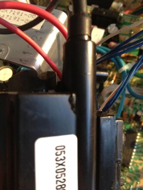
Damn thing was brand new. I've always heard about bad batches of flys but I've never ran into one. Well, looks like it happened this time. I re-installed the old flyback and when I powered the chassis on again, I got vertical collapse and then D13 smoked/shorted. So I replaced it, checked everything in that area, it all checked good and reinstalled/turned the chassis back on again. Poof! Fuse blew. HOT shorted.

So now I've got a lot more troubleshooting to do while I wait on the new HOTs I ordered to come in. ARGH!!


I got the Flyback from TwistedQuarter. I've ordered MANY cap kits/flys from them and NEVER had any issues. I don't even remotely consider it their fault. How could it be? As with all things electronic, you never know how long it's going to last. Regardless, I contacted them and told them what happened and I am awaiting a response. Hopefully, I can get a replacement but now I have a dead chassis that was working before that I have to fix. That's the most frustrating part for me.

On the vertical collapse issue, let me just say that I've never had a K7000 in VC that wasn't an IC issue but I have to wait until my new set of HOTs arrive (ordered 10 of them because I'm tired of never having any on hand) to start testing them. Oh well. First world problems.

Partial Success!!

I received my HOTs and some solder wick from MAT Electronics today. Started troubleshooting....

-) Re-installed original flyback.

-) Installed new HOT.

-) Critical Safety Cap(s) test good in circuit.

-) VR was shorted across pins 3 and 4.

-) Replaced VR.

-) R107 tested OPEN in circuit. Replaced R107.

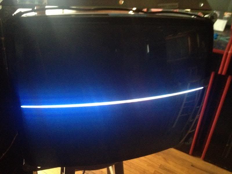
Found no other issues so I re-installed the chassis and powered it up. It fired right up but my exuberance was short lived because it was in vertical collapse. Damn. What's next? IC1?
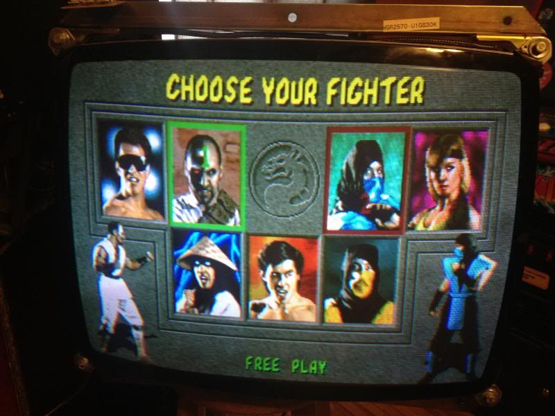


Total Success!!

-) Tested R101 and it's traces. Good.

-) Replaced C51.

Still collapsed.

-) Tested R91 in circuit. Supposed to read 1.2 ohms (basically shorted). Meter didn't ring so I removed it from the circuit to find that it was completely open and burned up...


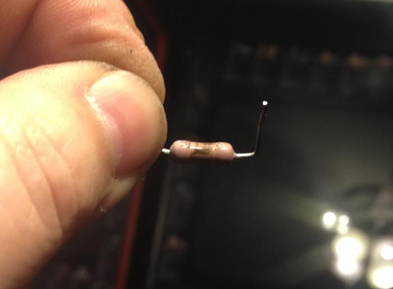
-) Replaced R91 and gave everything else another good lookover. Fired the chassis back up and...BAM! Collapse fixed and back up and running. Maybe this will help someone else in the future. TwistedQuarter contacted me and told me they are sending me a replacement flyback from a known good shipment so I'll install it when it arrives and hopefully it'll be ok this time.

-) All told, the bad flyback took out D13, HOT, VR, R107 and R91 (either directly or indirectly).


Current collection - 28 cabs, 4 pins. (32 machines and not enough room)

NoAffinity

  • Trade Count: (0)
  • Jr. Member
  • **
  • Offline Offline
  • Posts: 9
  • Last login:May 03, 2025, 08:06:23 am
Re: K7000 - Single Horizontal Line after Flyback and Cap Kit Replacement
« Reply #8 on: June 24, 2014, 07:36:01 pm »
Okay, thanks for the suggestions.  I will check the recommended things hopefully this weekend.  Am I correct to assume the board has to be powered to do the checks?

MK3FAN

  • Trade Count: (+7)
  • Full Member
  • ***
  • Offline Offline
  • Posts: 975
  • Last login:May 09, 2022, 07:07:29 pm
Re: K7000 - Single Horizontal Line after Flyback and Cap Kit Replacement
« Reply #9 on: June 24, 2014, 09:21:26 pm »
Okay, thanks for the suggestions.  I will check the recommended things hopefully this weekend.  Am I correct to assume the board has to be powered to do the checks?

To check resistors and diodes? No. Diodes can be checked in the circuit with the power off. Resistors (for the most part) can also be checked in circuit with the power off but the readings may not be reliable because you're reading through other components that could be influencing the readings. If, for instance, you're trying to read across R91, it should read shorted (1.2 ohms) in OR out of the circuit.
Current collection - 28 cabs, 4 pins. (32 machines and not enough room)

NoAffinity

  • Trade Count: (0)
  • Jr. Member
  • **
  • Offline Offline
  • Posts: 9
  • Last login:May 03, 2025, 08:06:23 am
Re: K7000 - Single Horizontal Line after Flyback and Cap Kit Replacement
« Reply #10 on: July 06, 2014, 12:30:20 pm »
Okay, here's I've got so far:

check R91 - 1.2 ohm 2 watt - measures 1.8 ohm

check D13 - often goes out. - cannot find this on my board.  Where is it located?

Check the polarity of C40 - 2200uF 35 volt - good

Check D25 can go open or shorted. Infinite resistance in both directions at first.  After multiple re-tries, I get infinite in one direction and a reading of 248 (set to 2000k) in the other direction

Check polarity of C48 - 100uF 35 volt. good

At R107, I am getting approximately 1200 ohms in one direction and infinite resistance in the opposite direction.
« Last Edit: July 06, 2014, 12:37:01 pm by NoAffinity »

lilshawn

  • Trade Count: (+3)
  • Full Member
  • ***
  • Offline Offline
  • Posts: 7513
  • Last login:Yesterday at 04:01:19 pm
  • I break stuff...then fix it...sometimes
Re: K7000 - Single Horizontal Line after Flyback and Cap Kit Replacement
« Reply #11 on: July 06, 2014, 03:54:59 pm »
d13 is buried in behind the flyback and heatsink

NoAffinity

  • Trade Count: (0)
  • Jr. Member
  • **
  • Offline Offline
  • Posts: 9
  • Last login:May 03, 2025, 08:06:23 am
Re: K7000 - Single Horizontal Line after Flyback and Cap Kit Replacement
« Reply #12 on: July 06, 2014, 04:05:46 pm »
Thanks lilshawn, I found it.

Re-posting my above findings along with findings from D13.  Any thoughts as to cause?

check R91 - 1.2 ohm 2 watt - measures 1.8 ohm

check D13 - often goes out. - Testing in one direction, ohms gradually increase until reaching infinite resistance.  Testing the other direction, ohms gradually decrease.  I didn't leave the multimeter on long enough to actually see it reach zero.

Check the polarity of C40 - 2200uF 35 volt - good

Check D25 can go open or shorted. Infinite resistance in both directions at first.  After multiple re-tries, I get infinite in one direction and a reading of 248 (set to 2000k) in the other direction

Check polarity of C48 - 100uF 35 volt. good

At R107, I am getting approximately 1200 ohms in one direction and infinite resistance in the opposite direction.

lilshawn

  • Trade Count: (+3)
  • Full Member
  • ***
  • Offline Offline
  • Posts: 7513
  • Last login:Yesterday at 04:01:19 pm
  • I break stuff...then fix it...sometimes
Re: K7000 - Single Horizontal Line after Flyback and Cap Kit Replacement
« Reply #13 on: July 06, 2014, 04:27:17 pm »
to properly test diodes, you must remove them from circuit (or at least, lift out one side) otherwise surrounding circuitry effects the result.

you should also use the diode test function on the multimeter which will show the forward and/or/reverse voltage rating of the diode.

a diode can still diode under the low voltages used during test, but fail under load or high voltages present while in operation. Be aware.

if all you got is ohm resistance checking, a basic quick and dirty diode test is like... you don't want shorted or open in both directions. but you really need to use the diode test function. good diode will stay reading 0 (or O.L) in one direction (depending on your manufacturer), and like 0.521 in the other. if it reads 0.000 it's shorted...if it stays OL then it's open and no good.

NoAffinity

  • Trade Count: (0)
  • Jr. Member
  • **
  • Offline Offline
  • Posts: 9
  • Last login:May 03, 2025, 08:06:23 am
Re: K7000 - Single Horizontal Line after Flyback and Cap Kit Replacement
« Reply #14 on: July 07, 2014, 10:28:21 am »
Okay, I don't want to take this thread off topic, but I am very eager to get my cabinet up and running ASAP, and the troubleshooting/replacement process is clearly going to take more time than I have to commit at the moment.  Not that I won't get to it, and post findings, but I'm hoping there is a more immediate resolution.

With that said, my monitor is a 25".  If am able to source a cabinet for parts locally, with a K7000 monitor, would it have to also be a 25", in order to swap the video board into my existing cabinet?  For instance, if I found a K7000 cabinet with a 19" monitor, would that work?

lilshawn

  • Trade Count: (+3)
  • Full Member
  • ***
  • Offline Offline
  • Posts: 7513
  • Last login:Yesterday at 04:01:19 pm
  • I break stuff...then fix it...sometimes
Re: K7000 - Single Horizontal Line after Flyback and Cap Kit Replacement
« Reply #15 on: July 07, 2014, 06:51:50 pm »
Okay, I don't want to take this thread off topic, but I am very eager to get my cabinet up and running ASAP, and the troubleshooting/replacement process is clearly going to take more time than I have to commit at the moment.  Not that I won't get to it, and post findings, but I'm hoping there is a more immediate resolution.

With that said, my monitor is a 25".  If am able to source a cabinet for parts locally, with a K7000 monitor, would it have to also be a 25", in order to swap the video board into my existing cabinet?  For instance, if I found a K7000 cabinet with a 19" monitor, would that work?

no.

the deflection boards are specifically tuned to the particular size tube they are to be used for.

in order to use it on a different sized tube, there are a mess of components that would have to be changed out.