I've been working on my project in segments (I pretend I'm working on each segment in parallel, but I'm just kidding myself). This segment, or portion of the project, is a “Starfish Ray.” If you don't figure why it's called a such, then it proves that I'm just a ---smurfy--- teacher... or maybe I'm not typing stuff out..... I dunno.

I'm not going to go into too many of hooplas, trials, tribulations and hours I spent crying in the corner. It's pictures and progress on this one. Maybe a few explanations here and there. I actually wrote this thing several times over and well... gave up I guess and just decided to dive in.
I'm not sure if there is a preference for pre-text or post-text on the photos. I decided to do post-text. Let me know if there is different preference by the majority
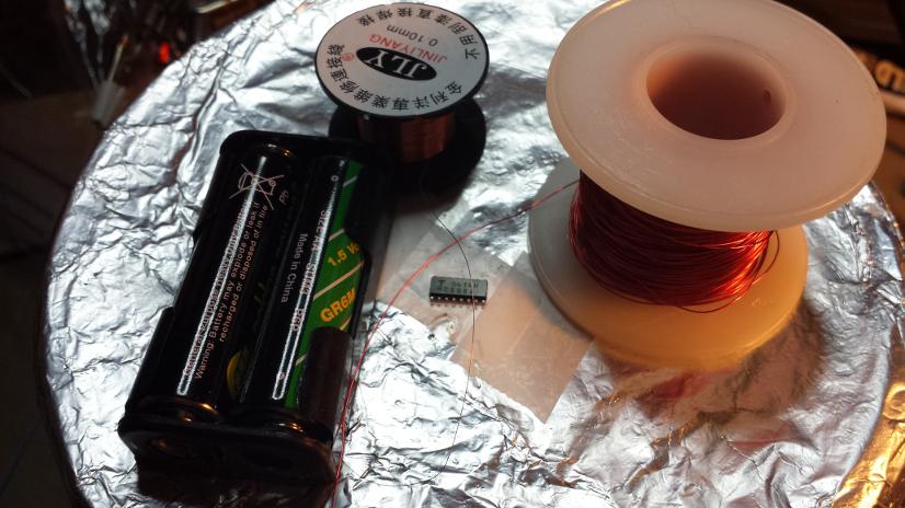
The round board in the middle is the Ray. Technically, it's a breakout board for a T/LQFP32/44 package IC from ElecFreaks. In all honesty, I won't use a breakout board like this again, not even for protoyping. I would certainly not recommend said board to anyone else for any compelling reason. The most annoying problem is there isn't any ground or VCC plane on the bottom. Yep, it's a single sided board. The second annoying aspect is there is very little there for supporting circuitry. I'll get into the details of that later.
But.... this is the first one so I can deal with it. Alongside that board are two packs of 1M and 10k 0805 SMT resistors. To the right are 1206 pink SMT LEDs, next to them are a trio of Serial-Parallel shift registers in a SOL16 package (also SMT). The black spool is 0.1mm enameled wire and the white spool is either 28 or 29 gauge enameled wire. The package of black bits are 1x4 female headers.
The unimportant bits in the background include things like my homemade flux, hacked/gutted printer and whatever.
First thing I did was assemble and solder the TQFP board. But I took so few pictures (as in none) and I misplaced the camera as of this posting. I'll put information about it in a little while.

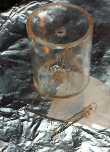
This is the best shot I could get but this shows a (blue) LED embedded in an acrylic tube. I used a concoction of acrylic and TAP Plastics acrylic solvent to make a thick glue about the same consistency as fresh Elmers school glue. Then I attempted to “build up” around the LED without toasting the lens. The stuff evaporates so quickly I had no problem building up the acrylic at all. The whole point of this exercise was to see whether the solvent would ruin the LED case and whether it would hold. The crack in the tube wall is from the shop. This tube is a sample from TAP so I couldn't really complain.

This shows only one LED but there were, in fact, two. The first LED simply popped out once the acrylic solidified. Apparently liquid acrylic shrinks just a tiny bit, but that was enough I guess. The second (pictured) popped out when I attempted to tin the leads. This was
despite coating the back of the LED in acrylic in an attempt to encapsulate the light.
I learned two things from this:
- Acrylic and solvent have ZERO affect on the LED
- Do ALL of the soldering before embedding LED into acrylic.
Good.... that was the point of this exercise. To figure this stuff out before spending shitloads of money and time on something that isn't going to work.
I didn't take pictures, but after the acrylic failed I decided to try a bit of 100% Silicon. I read a few forum posts that this is effective for holding LED in/against acrylic as long as you don't try to rip them out. But in those same posts, a lot of people cited that the acid (the vinegar smell as the silicon cures) harms electronics. It's apparently possible to buy some kind of “acid-free” silicon specifically for electronics or whatever. While I'm big on true preservation, I'm not shelling out money for acid free anything if I don't know if it's going to work. So I gave it a shot with some "vinegar smell" silicon I had sitting around. So using my trusty, and already chipped, X-Acto blade, I worked some silicon against one LED and set it aside to cure.
The silicon didn't work. It gripped like the devil on the LED. Even peeling it off with the X-Acto blade was more work than what the LED was worth. At least I have plenty of spare LEDs to fiddle with. However, the silicon wouldn't grip the Acrylic
at all. I could hear an audible "pop" as I tweaked the LED around just a tiny bit. I'm not 100% sure if Acrylic manufacturing involves mold release agent or not. Or maybe there were trace solvents in the plastic?

I'll clean the tube with some mild cleaner and try again but I'll bank on getting the same results. I'll have to refer to the TAPS people or the Acrylic specialists to see what went wrong.

Tinned and soldered a 470 Ohm resistor (a bit strong for 5 volts, but these are bright anyways) and wire to the LED. Yes, I could've wound the wire better, but this isn't a mission critical application so a
Western Union Splice isn't strictly necessary. I didn't want to waste shrink tubing so there isn't any on there. There probably won't be any in the final build either since I'm considering a different type of LED anyways. This isn't installed because...well... still working out the adhesive problem.

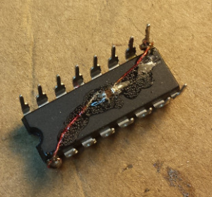
Only one IC is pictured, but there are actually two involved. These are the same shift registers pictured earlier in different package. These are my breadboard IC's. I'm not really sure why, but I always use the same IC's whenever I'm breadboarding so they never end up in a final circuit.
Big brother gets some enameled wire on two of his legs. That small square in the middle of the circle is a .1uF 0603 SMT capacitor. This is my second attempt. The twin has the capacitor on
top of the IC. I wanted to see which would be better. IMHO, they're about the same but installing the cap on the bottom let me use the IC installation tools without too much fuss. I admit I could've wrapped the leg just a
tad tighter but eh, first time.

Both twins got a dab of liquified Acrylic. Surprisingly, it's reasonably sturdy though I honestly don't know how well it will stay there if I chip away at it or whether it would melt once a little heat is applied. Though that could be advantages if I have to rework this.
I think in the short term, using acrylic is fine but I wouldn't consider it in a production piece. Too risky for too many things to go wrong. Ultimately, I decided not to do the same thing to the SMT IC's. I feel the acrylic won't hold well over the long term and might suffer heat damage. I suppose I could use dabs of JB Weld to hold them in place, and in the future I might. But for this project, I'll take a different direction.

To give a sense of scale of the SOL16 package, I tossed in a pair of AA batteries. Sorry, I didn't have any coins available at the time and I didn't feel like going back into the house to get a couple.

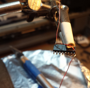
After tinning the leads, I soldered on some 28/29AWG wire. I decided to do top over rather than bottom under because this is a SMT component and there is no space underneath for a cap. However, I don't like how one of the leads turned out because of the difficulty in manipulating such small wires. I desoldered these leads after finding a sample SOL-16 breakout board from ElecFreaks in my parts bin. (I'll post pictures after I find the camera) I like this particular board better. It's better designed and there is specific consideration for two SMT capacitors with pads close enough to fit my 0603 0.1uF capacitors. NICE!

Still no ground plane underneath

One weird quirk is that all the break out pins are on one side of the board in a 2x8 layout. I like that for my project since the headers I'm using are double rows but... it makes it impossible to use on a breadboard. Weird


Quick game foryall. The picture shows three different IC packages for a 16 pin IC. The topmost is a DIL package, very common and the easiest to work with. The 2nd picture is a type of SMT package. I have a few IC's that use this package. The package I'm using is the bottom most one, the SOL. The marking for PIN 1 on the SOL is subtle and hard to miss. It took me several minutes of studying the data sheet before I realized where the marking is. Both the DIP and SOP packages have a notch on the left in the drawings. PIN 1 is always the first pin to the left of the notch. This is a regular thing to keep manufacturers and assemblers sane. The SOL package is missing that notch. That stumped me for a while until.... Heh, I'll let you guys figure it out or you can wait until the next update

And what is Starfish? That's coming soon if you haven't figure it out yet


 Home
Home Help
Help Search
 Login
Login Register
 Send this topic
 Print
Print


