Ok, if you buy a multimeter you should be able to look at the manual to see how to set it to test for continuity. If you borrow one, ask the person you borrow it from to set it for you. Basically you want one of the probes plugged into the COM port and one into the Volts/Ohms mA port. There are many types of multimeter but you want to set the dial (if there is one) to something like the yellow circle the picture below:

The first thing I would do would be to check your grounds.
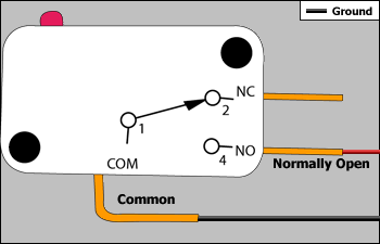
Have a look at the CP wiring and you will see there are wires connected to each microswitch like the diagram below:

With the multimeter set and turned on check that its working by touching the probes together, you should get a BEEP and/or a display on the screen telling you that there is continuity between the two probes.
Then touch one of the probes onto one of the GND (Ground) screw terminals of the IPAC and hold it there. Then go round and touch the metal part of each quick disconnect that is attached to the microswitches common tag (refer to the diagram above). You should get a strong BEEP when you touch each one like you did when you touched the two probes together. If one or more microswithes don't beep when you touch them that means there is no continuity (i.e a broken wire / connection). You will then need to repair/replace that wire or possibly a whole ground loop depending on how it has been wired.
If you find faults and repair them test the new connections with the multimeter and if all is well test the controller in MAME etc.
If you didn't find any faults or it did not fix all of the faults you may have faults with the wiring connected to the NO tag on the microswitches.
To test these you need to do a similar check to the ground check but you don't keep one probe one of the GRD terminals like you did before, you will have to move the probes for each microswitch.
If you can see/trace the wires from each microswitch back to the IPAC that will be helpfull but don't worry if you cant. If you can see where the two ends of the wire terminate (IPAC terminal and each microswitch) then probe the appropriate screw terminal on the IPAC and the NO tag of the microswitch. You should get a BEEP as before.
If you cant trace the wires (it does look to be an organised mess!) then hold one probe on the NO tag of the microswitch and then with the other probe, go round the IPAC and touch each screw terminal. One of them should beep (but hopefully not the GND terminals, unless you have a button/joystick depressed). If you don't get a beep with a/some wires then you know you have a problem. Your best bet then is to try to trace those problem wires and repair/replace as necessary.
If all of that does not fix it you either have a/some faulty microswitches or a faulty IPAC.
To test the microswitches remove both disconnects from the tags and then put one probe on the COM tag and one on the NO tag. You should not get a beep but when you press the appropriate button/joystick direction you should get a beep. If you do check the microswitches I would do them one by one as you could soon get in a mess if you remove all of the disconnects.
Im no expert by any means but thats what I would do. Hope that helps a little.


 Home
Home Help
Help Search
 Login
Login Register
 Send this topic
 Print
Print


