Main Restorations Software Audio/Jukebox/MP3 Everything Else Buy/Sell/Trade
Project Announcements Monitor/Video GroovyMAME Merit/JVL Touchscreen Meet Up Retail Vendors
Driving & Racing Woodworking Software Support Forums Consoles Project Arcade Reviews
Automated Projects Artwork Frontend Support Forums Pinball Forum Discussion Old Boards
Raspberry Pi & Dev Board controls.dat Linux Miscellaneous Arcade Wiki Discussion Old Archives
Lightguns Arcade1Up Try the site in https mode Site News

Unread posts | New Replies | Recent posts | Rules | Chatroom | Wiki | File Repository | RSS | Submit news


Author Topic: It's back again!  (Read 12836 times)

0 Members and 1 Guest are viewing this topic.

M.Lanza

  • Trade Count: (0)
  • Full Member
  • ***
  • Offline Offline
  • Posts: 192
  • Last login:October 09, 2015, 09:51:03 am
It's back again!
« on: July 04, 2008, 02:32:57 pm »
This is my 2nd 1/2 mame project. I didn't post my first project and 1/2 here,
but it just involved a generic jamma cab a pc and some hacked psx controllers.
The 1/2 part involved removing the pc and replacing it with an xbox with an
x-arcade encoder because mameox works really well with lightguns.

I was using a tv with s-video as a display and eventually grew dissatified with the
display quallity, so this cab was eventually scrapped.

My wife got this cab for me as a birthday present a couple of years ago.


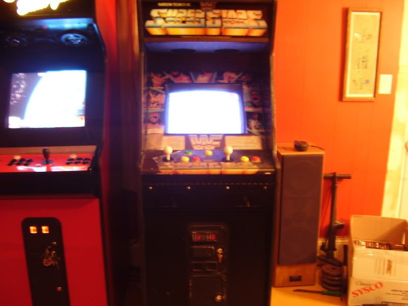
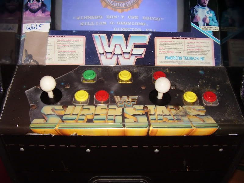
It needed quite a bit of work and I really dislike wrastlin', so I started converting it
to a game that I would enjoy more and decided that I really couldn't go wrong with tetris.

I didn't take any pics of the inside of the cab when I got it, but the jamma harness was hacked
into the original M.A.C.H. 3 harness somehow and I didn't really know what was going on inside
the cabinet, so I removed everything and started from scratch.

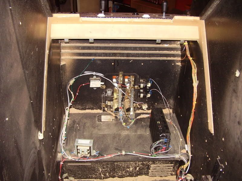
I used Bob Roberts site quite a bit, first to rebuild the the electrohome g07 and remove the
tearing at the top right of the screen, then built the jamma harness and power circuit.
I ended up learning quite a bit.

The game I used was the original atari tetris which used omni-handed controls.
I would have had to have another metal cp made and I wasn't sure how to accomplish
that, so I just filled in all but one button hole per player.
The start button is mapped to the first action button, so I didn't see a need for a dedicated
start button.

I covered the control panel and the area under the marquee with a vinal (sp) that I got
from Happ along with some other parts I needed such as the power cord, ac line filter,
isolation transformer, jamma harness, joysticks, and buttons.

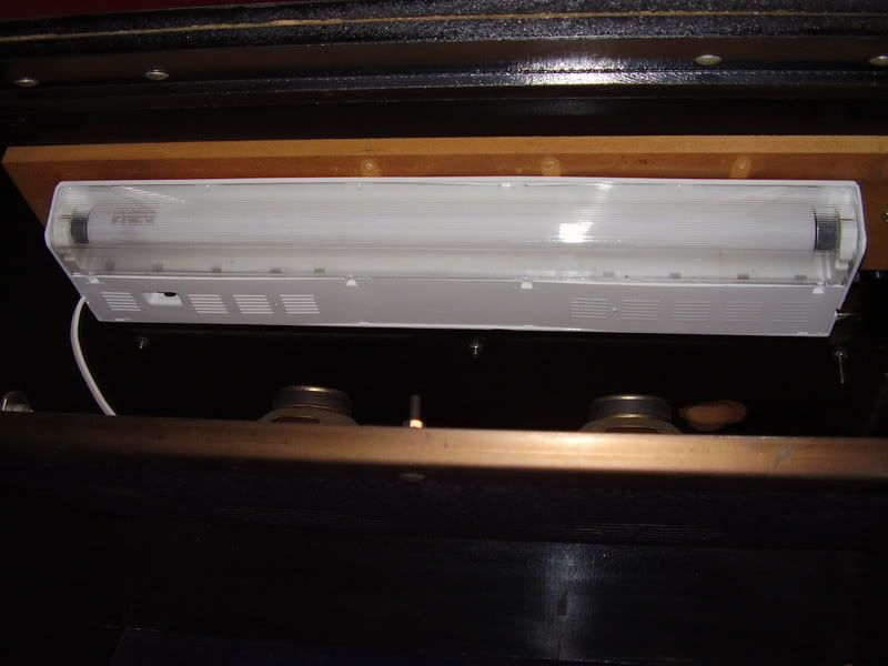
I replaced the dead marquee light with a under counter light I bought from walmart.

Here are the pics of the finished product (minus T-molding).


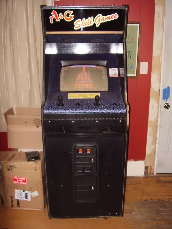
Since then, I replaced the happ supers with sanwa jlw's, bought a tetris plus board
and added dark blue t-molding.
Tetris plus needed a dedicated start button, so I knocked out a couple holes to put them.

I don't have any pics of that stuff, but it's redunant anyway, so i'll go on now to how I'm
currently molesting the cabinet.

So far I've decided on a vertical cabinet ( too late now) for golden age classics and
vertical shooters, mostly because by control panel is limited to 2 action buttons per
player which severly limits the amount of horizontial games I could play on it and
vertical games displayed on a 19" horizontial monitor is a travisty to all that is holy.

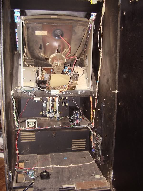
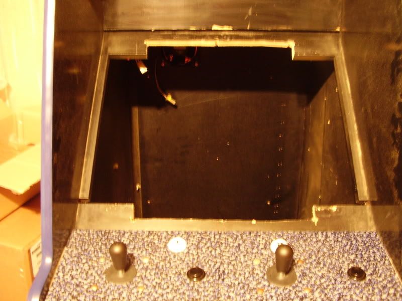
So far, I'm performing some modifications required to mount the monitor vertically in the cabinet.

I had to remove the shelf that the monitor sat on and cut out some of the wood sections
directly behind the monitor glass to get it to fit.


The monitor current sticks out about an inch beyond where the monitor glass will go
so I'll be cutting some shims / mounting brackets from a peice of oak plywood with
the band saw at work tonight on my lunch break.

I decided to use an xbox in my cabinet instead of a pc it's cheaper and easier to
work with since it natively sends out a 15khz signal.
I can prepare a stock xbox to work in my cabinet in a couple of hours in the
case of hardware failure.

I'm currently waiting on an adapter from ultmarc to connect the xbox to the monitor.


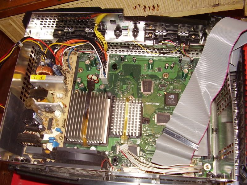
I dismantled it to solder in an external power switch operated from the controller interface.

I will be interfacing with the xbox using a good old controller hack.
I'm working on a really thin budget, so the ipac plus adapter plus cable was out of
the question. the last time I used an x-arcade interface and adapter with the xbox.
I had to severly modify the harness to work with my old cp and I don't feel like
going through that again.

I'll be using the street fighter 15th annaversary controllers as my interface.


I already had one laying around so I decased it and decided that it would work
well for the hack, so I ordered another from ebay.


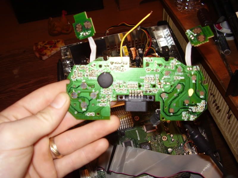
The best thing about this controller is that all of the buttons are digital,
so it should be no different from a psx controller hack.

I'll be wiring these controllers to a DB25 adapter I have and mounting them inside
of a vhs cassette box.


That's all I got so far, I've got to work all weekend so I can't make any progress
untill monday.

I've also got an idea involving proximity switches, but it will be a while before
I can hash that into a testing stage.

« Last Edit: August 31, 2010, 03:45:51 pm by M.Lanza »
Trample the weak, hurdle the dead

M.Lanza

  • Trade Count: (0)
  • Full Member
  • ***
  • Offline Offline
  • Posts: 192
  • Last login:October 09, 2015, 09:51:03 am
Re: My generic vert xbox cab project
« Reply #1 on: July 08, 2008, 06:07:43 am »
I'm free of the burden of working ( for a couple of days ) so I've made some progress. ( not much )

I used a bandsaw at work to cut some spacers from plywood, but i've still got more cutting
to do on those with a jigsaw later.
I've also got a couple extruded aluminum bars that I thought would work well with mounting the monitor.


I removed the plastic that was attached to one of the aluminum beams, and was rewarded with 10
hex head bolts and mounting nuts.


The nuts slide into the beam, allowing me to attach things to it using the bolts.

After cutting down the beams so they could fit along the the width of the cabinet
I attached the beams to the monitor.


It turned out quite well, perfect really, better that I thought it would.

That's the extent of my progress on the monitor mounting.
I should have the monitor mounted by the end of the day.

I kind of sidetracked a little and decided to work on my proximity switch idea.
I've made good progress and discovered setbacks preventing me from moving foward with the idea.

I work at a plastic injection molding factory. One day at work, while I was cleaning a material vacume loader,
I touched one of the material level sensors and noticed that the vacume feeder would turn on if nothing was
touching it, but as soon as I touched it, the vacume feeder turned off.
I then thought that it would be cool to use somthing like that in a mame cabinet and this is what I came up with.

http://www.ifmefector.com/ifmus/web/dsfs!KI0203.html

It's a capacitive proxmity switch.

At $130.00 each, it seemed like quite a gamble to take on a theory, but I was able to get
a pair of them on ebay for about $40.00.
Quite a bit more reasonable, but I should have paid a little more attention before I bought them.


Here is a prototype I built of the switching mechanism.
The switch can operate using dc voltage, so I wired it up to a vibration motor from a
dual shock psx controller and a 9v ac adapter.


I've also posted a youtube vid showing it in action.

[youtube]http://www.youtube.com/watch?v=AkVaGoYbynQ[/youtube]

The idea was that I could mount the switch behind the tinted monitor glass
making this switch completely hidden.
I could then touch the area of the glass with the switch behind it and it would send power
to the dc motor and the offset metal peice would activate the microswitch.

The microswitch would be connected to the remote power wire from the xbox
which would be connected to a smart strip causing the whole cab to power on.

You can see from the video that it isn't going to work that way wecause the
the capacitive proximity switch is a normally closed circuit.
I can still make this work by connecting the xbox's remote wire to the NC tab on the microswitch,
but that would mean that power would be constantly applied to the dc motor possibly causing
it to burn up or catch fire after an extended period of time.

It's nice to see that my idea worked. At least I know that it's plausable, but I either have to find
another dc current operated switch with a normally open circuit, or find some way to make this switch
do what I want some other way.


« Last Edit: July 08, 2008, 06:14:05 am by gimp_hand »
Trample the weak, hurdle the dead

severdhed

  • Trade Count: (0)
  • Full Member
  • ***
  • Offline Offline
  • Posts: 2975
  • Last login:December 14, 2024, 05:01:52 pm
  • RIP Dinosaur Hippo
Re: My generic vert xbox cab project
« Reply #2 on: July 08, 2008, 03:33:37 pm »
looks like an interesting project, keep us posted.  does mame on the xbox support monitor rotation?  it has been a while since i have used it, and i don't remember trying to rotate it.   i may have to look into this for a future project.  right now i have started on a gun cabinet, but it is just a playstation 2 with a few gun games...i was not aware that xbox mame worked well with lightguns, because that would be a much better option for me. 
Current Projects:      Zak-Man | TMNT Pedestal | SNES Pi | N64 Odroid
Former Projects:     4 Player Showcase | Donkey Kong | iCade

BASS!

  • Just have fun.
  • Trade Count: (+1)
  • Full Member
  • ***
  • Offline Offline
  • Posts: 837
  • Last login:August 10, 2013, 03:12:33 am
Re: My generic vert xbox cab project
« Reply #3 on: July 08, 2008, 04:24:09 pm »
Wow now that is an idea for a button. Is it sensetive enough to where a good game of (insert 2p fighter) would cause your monitor to rotate on its own.

M.Lanza

  • Trade Count: (0)
  • Full Member
  • ***
  • Offline Offline
  • Posts: 192
  • Last login:October 09, 2015, 09:51:03 am
Re: My generic vert xbox cab project
« Reply #4 on: July 10, 2008, 03:59:28 pm »
looks like an interesting project, keep us posted.  does mame on the xbox support monitor rotation?  it has been a while since i have used it, and i don't remember trying to rotate it.   i may have to look into this for a future project.  right now i have started on a gun cabinet, but it is just a playstation 2 with a few gun games...i was not aware that xbox mame worked well with lightguns, because that would be a much better option for me. 

The screen rotation settings are in the setup menu.

Well, the lightgun games that are emulated properly in that version of mame work really well.
There are games that work and some that dont, but i've played quite a bit of zero point, police trainer,
zombie raid, and lethal justice using the madcatz blaster.

I've thought about placing the guts of the madcatz gun into a real arcade lightgun shell but never qot around to it.

Wow now that is an idea for a button. Is it sensetive enough to where a good game of (insert 2p fighter) would cause your monitor to rotate on its own.

The monitor isn't going to rotate. I'm just placing it vertically in the cabinet.
The button is going to be used to power on/off the cabinet, though I may wire up another as an escape/exit switch.

I test mounted the monitor in the cabinet.
All I have to do is figure out a way to secure it in place, but I currently have other issues with the cabinet,
so it's a low priority right now.


I had to lay the cabinet on it's front in order to test mount the monitor without it falling back into the cab,
when I did that I got a refreshing look at the terrible shape the base of the cabinet is in, so I decided to do somthing about it.


It seems as though three of the cabinet's legs had broken off long ago, so the cabinet's side panels were it's
only means of support for quite a while which has caused irrepairable damage to the bottom of the cabinet.

It turns out that the cabinet's sides are made of some kind of material that resembles a stack of paper.
There is no way bondo is going to fix this, so i've started the process of covering it up.

The way the cabinet sat after it's feet were broken off caused some stress to the body and it's side panels
have started to split apart from eack other at the bottom, so I have to make sure that the cover up will also
renew the cabinets structural integrity in order to prevent further damage.

The only way I can think of describing what i'm doing is that i'm building a wood box around the base of the
the cabinet which will be secured to the cabinet's side panels and a basic frame at the bottom.

I've already started working on the frame which the cabinet is now sitting on.


I really wasn't planning on doing any cosmetic work on the cabinet,
but since i've already started improving it, I may as well make it look better.
« Last Edit: July 10, 2008, 04:08:45 pm by gimp_hand »
Trample the weak, hurdle the dead

SNAAKE

  • Trade Count: (+29)
  • Full Member
  • ***
  • Offline Offline
  • Posts: 3564
  • Last login:Yesterday at 02:07:33 pm
  • my joystick is bigger than your joystick !
Re: My generic vert xbox cab project
« Reply #5 on: July 12, 2008, 12:08:55 pm »
u probably want more buttons. everything else is looking good so far.

where can I order those db25 pin connectors ? I need to rewire my control panel as I want xbox360 support in my cabinet since sf4 and HD remix will be on 360 soon.

« Last Edit: July 12, 2008, 12:10:43 pm by SNAAKE »

M.Lanza

  • Trade Count: (0)
  • Full Member
  • ***
  • Offline Offline
  • Posts: 192
  • Last login:October 09, 2015, 09:51:03 am
Re: My generic vert xbox cab project
« Reply #6 on: July 12, 2008, 05:43:09 pm »
u probably want more buttons. everything else is looking good so far.

where can I order those db25 pin connectors ? I need to rewire my control panel as I want xbox360 support in my cabinet since sf4 and HD remix will be on 360 soon.


I don't remember where I got the connector from. I just found it in my junk box.
I checked out the company name on the pcb and found the manufacturer's site.

http://www.weco.ca/1_0/1_1/1_1_show_product.asp?type=B&id=547

I found some other sites selling these, but the average price seems to be about $35.00 each.

Two action buttons per player seems like enough. I don't remember seeing any vertical games that had more than two.
Would I be missing out on anything good?


I started building the box around the base of the cabinet.


I'm just waiting for the tempreture outside to drop a bit before I start cutting more wood.


I used the smallest bit I have to drill pilot holes in the back panel, but the screws wern't much larger
than the pilot holes and didn't hold well enough, so I just drilled the screws straight into the wood
without drilling pilot holes and now the board is holding strong.
It would take a good sized crowbar to remove those boards from the cabinet, so I think i'm off to a good start.

I am leaving a space on the bottom of the cabinet open for ventilation purposes, but it's impact on the overall
strength of the base once it's completed should be minimal.
« Last Edit: July 12, 2008, 06:33:44 pm by gimp_hand »
Trample the weak, hurdle the dead

M.Lanza

  • Trade Count: (0)
  • Full Member
  • ***
  • Offline Offline
  • Posts: 192
  • Last login:October 09, 2015, 09:51:03 am
Re: My generic vert xbox cab project
« Reply #7 on: July 13, 2008, 07:51:55 pm »
I've finished constructing the new cabinet base.


This was the bottom at about 8:A.M. but it has changed since then.

I had to cut out small sections of the cabinet side panels that the t-molding runs along
in order to attach one of the planks onto the front of the cabinet.


The section that had to be removed is visable in the background of this pic.


I then attached the front plank.


I think it turned out all right. The plank is just about flush with the t-molding so it doesn't look too bad right now.

I then started attaching the side planks and discovered that I didn't have enough wood to finish the base,
so I removed a plank from the bottom of the cab and used it along with another to finish the left side of the cabinet.


Some of my measurements were a bit off and I went a little overboard with the screws,
but it's nothing I can't fix with a can of bondo and a bit of sanding.


This is the finished bottom with the body planks attached.
I'm still trying to decide on wether to use leg levelers or castors.


The cabinet standing upright on it's new base.
It kind of looks like a shorter cabinet sitting on a pedestal.

The new base only adds about 1 1/2" to the width of the cabinet, so I don't think it will
look too unnatural once everything is filled, sanded, and painted.
« Last Edit: July 14, 2008, 05:55:26 am by gimp_hand »
Trample the weak, hurdle the dead

M.Lanza

  • Trade Count: (0)
  • Full Member
  • ***
  • Offline Offline
  • Posts: 192
  • Last login:October 09, 2015, 09:51:03 am
Re: My generic vert xbox cab project
« Reply #8 on: July 23, 2008, 12:42:12 am »
I got more stuff done today, with more still to do before I sleep.

I'll start off with the monitor mounting.

The weight of the monitor will be supported by the front section behind the monitor glass
as well as the cabinet sides which now have the aluminum rails attached with a bracket
system made up of plywood, L brackets, carrage bolts, nuts, and washers.

The first thing I did was to modify some carrage bolts to fit in the grooves of the aluminum rails.


This required a few minutes with the bench grinder before the carrage bolts would fit.


I then had to modify the L brackets.


First, I used some bolt cutters to trim the brackets down to a reasonable size and then
drilled out the holes to allow the carrage bolts to fit.


A carrage bolt was inserted into each end of both aluminum rails and the rails were attached
to the front of the cabinet with screws, then washers, the L brackets, and nuts were assembled
onto the carrage bolts in the rails then I cut off the excess bolt with bolt cutters.


I then used peices of plywood to push foward against the aluminum rails, slid the bracket
assemblies against the plywood and drilled holes from the hole in the bracket straight through
the plywood and cabinet side.

Then I inserted carrage bolts through the holes in the cabinet sides and the brackets and attached them
with more nuts and washers and was left with a nice adjustable method for mounting the monitor.


Then it was disassembled because I had some bondo work and painting work to do.


This is the top of the cabinet with some large holes that needed to be patched.
When I first got the cabinet. one of the holes had an audio jack attached to a plate
which I assume was used for a set of external speakers.

I don't know what the other hole was used for.


This was where I first started sanding. Appearently, a large section of the cabinet side
was damaged and filled in with bondo, but this section was left with large pits that needed to be filled
along with large gouges in both cabinet sides.

I spent a good deal of the day occupied with sanding. I'm pretty sore right now.

Once I finished sanding, I filled in the holes in the top of the cabinet, the pits and gouges
in the sides of the cabinet, and the screw holes in the front of the cabinet.
Then I sanded some more.

Once I was satisfied that everything was nice and smooth ( for the most part ),
I removed most of the sanding dust with a dry rag, and then finished up with a damp sponge.

I then waited a few minutes and started painting.

I started off with two cans of flat black as my base coat, then finished up with three cans of semi-flat black.


It started getting dark, so I brought the cabinet back inside.
In the morning, I will take some polishing compound and give the cabinet a good rubbing.

Currently, I'm working on the cabinet base.
I'm covering it with aluminum flashing that is normally used in roofing applications.


So far, it's proving to be very difficult to work with, so the end result will probably be far from perfect.

On the brighter side, this stuff is wide enough for me to attempt to cover my control panel with.
It should look pretty sweet.


On different but related matters, I've managed to aquire a couple more capacitive proximity switches from ebay

http://www.ifmefector.com/ifmus/web/dsfs!KI5208.html

These can be supplied with 10 to 36 VDC, so they will work with my power source, with the
benefit of switching between a normally open and normally closed circuit with a jumper wire.


I've decided to scrap the street fighter controller hack for somthing a bit more advanced.

I was reading the FAQ and came across the console interface section which had a link
to a 49-way to analog circuit diagram.

http://www.arcadecollecting.com/info/49way_to_Hall.gif

Well, a vertical oriented cabinet is pretty much worthless if it can't play sinistar, so I decided to try my luck.

I contacted tim from arcadecollecting.com who developed the circuit to find out where I could
find the necessary component's for the circuit, because I didn't know what the heck to look for.
He has been of great assistance and I can't thank him enough.

So far, I've ordered the IC's and 49-way joysticks as well as a couple of xbox s controllers.
I'm still waiting for everything to be delivered.

I have hope that I can make this work, because it would be so awesome.
If by chance, my lack of skill prevents me from making this work, I'll concede defeat and
buy a gpwiz 49 and install a pc instead of an xbox.

I'll just have to wait and see.


« Last Edit: July 23, 2008, 12:51:08 am by gimp_hand »
Trample the weak, hurdle the dead

M.Lanza

  • Trade Count: (0)
  • Full Member
  • ***
  • Offline Offline
  • Posts: 192
  • Last login:October 09, 2015, 09:51:03 am
Re: Vertical screen xbox cab project
« Reply #9 on: July 25, 2008, 08:58:05 pm »
I'm done covering the base boards.
It turned out to be much more difficult than I thought and it didn't turn out that great.
I guess I'm stuck with it for now since I'll be moving in about 6 weeks, but I can always
rip it off and start over later if it bothers me that much.  Meh.


I was considering covering my control panel with this stuff, but I need to practice on somthing else
before I even think about trying it.


I got the monitor mounted along with the proximity switches.
It took a while to finally get the monitor mounted, but it's nice and secure.
I still have some measuring to do to ensure that it is properly centered,
but it should take no more than a couple of minutes at the most.

The switches were installed after I attached quick connectors to the wires,
The switches should be flush with the back of the monitor glass and are far
enough from the controll panel that that won't be accidently activated during game play.
I'm not sure how they will do behind tinted glass, but i'll find out later once I adjust
their sensitivity settings.


Most of the hard stuff is done.
Now I just have to clean up the cabinet and start installing the electronic components.
I can also move onto my living room reclaimation project. :)

The smart strip was delivered last night while I was at work, I found it
on my front porch this morning when I came home from work.
I'm glad no one stole it.

I kind of find it hard to believe that my UPS packages don't get delivered untill about 8:00 P.M.
even though there is a terminal a couple of blocks from my house.

I got my package from happ today also.
Somehow, I kind of expected the 49-way joysticks to come with the connector harnesses
but I was wrong.

Anyway, I guess it's going to take me a bit longer than expected to see if I can interface these
with the xbox controllers since I won't have the cash to buy the harnesses untill next friday.
Oh well, I got plenty of work to do on the cabinet still, so I can wait.


Trample the weak, hurdle the dead

M.Lanza

  • Trade Count: (0)
  • Full Member
  • ***
  • Offline Offline
  • Posts: 192
  • Last login:October 09, 2015, 09:51:03 am
Re: Vertical screen mame project.
« Reply #10 on: August 04, 2008, 11:34:37 pm »
 :'(

I am mourning the loss of an electrohome G07.

I was mounting the xbox and other components to the bottom of the cabinet
when the dog decided he wanted to play.

He jumped on me with one of his toys and I jumped up and snapped the neck
glass with my head.

I'm really bummed about it.


It's not all bad though.
I just decased a 19" kds vga monitor and will be using that instead.

This means that I will no longer be using an xbox.

I do have a component to vga adapter, but I'm just going to use a pc.

This has been a major setback and has crushed my will to move on with the project
since I may not have it playable in time before I move.

I will move on though and have the cabinet together hardware wise before the move,
I'll just have to worry about the software configuration later on.
Trample the weak, hurdle the dead

Mauzy

  • Trade Count: (+2)
  • Full Member
  • ***
  • Offline Offline
  • Posts: 1191
  • Last login:September 23, 2020, 11:51:27 am
Re: Vertical screen mame project.
« Reply #11 on: August 04, 2008, 11:54:18 pm »
Damn dude, good thing you didnt get the crap shocked out of you. Good luck PC mame-ing that cab.
"Son, all hobbies suck. But if you keep at it, you might find you managed to kill some precious time."

M.Lanza

  • Trade Count: (0)
  • Full Member
  • ***
  • Offline Offline
  • Posts: 192
  • Last login:October 09, 2015, 09:51:03 am
Re: Vertical screen mame project.
« Reply #12 on: August 05, 2008, 02:42:53 am »
I discharged the monitor before removing it from the cabinet and hadn't plugged it in yet.

I got my new monitor mounted.


It didn't turn out too bad.
I lost about 1 1/4" of diagonal screen size, but I plan on buying either a 21" or 22"
monitor that I can swap out once I get settled into my new place.

I made the mounting board from a spare peice of plywood that I had laying around.
I thought that I wasn't going to be able to do it properly since i'm not a very good carperter,
but it turned out really well.
I was never too good at math, especially fractions, and it was only by the good grace
of my math teachers that I was ever able to pass any math classes, but all of my measurements turned out perfectly.
I have no clue where I learned how to multiply and devide fractions because I certianly didn't learn any of that at school.

Anyway, the monitor adjustment board is just kind of hanging from the monitor at the moment.
I plan on extending the cable and mounting the board on the back of my control panel
since I bought more heat shrink tubing than I think I will ever use.


I had planned on using a cheap car stereo, powered by a pc power supply and connected to the cabinets original speakers.


It didn't sound too bad considering that it's a cheap car stereo connected to a 25 year old set of speakers,
but I was getting a lot of electrical interference and constant feedback, so I removed that crap and bought
some hopefully decent pc speakers.


I'm thinking of removing the power and volume adjustment board and mounting it behind the coin door,
but at this point anything can happen.


« Last Edit: August 05, 2008, 02:46:15 am by gimp_hand »
Trample the weak, hurdle the dead

M.Lanza

  • Trade Count: (0)
  • Full Member
  • ***
  • Offline Offline
  • Posts: 192
  • Last login:October 09, 2015, 09:51:03 am
Re: Vertical screen mame project.
« Reply #13 on: August 06, 2008, 10:56:28 am »
I got the speaker system installed.
I had to chop up the case quite a bit since they wouldn't fit on the speaker panel as-is.

It took a while to remove the power transformer and volume control board and I had
to cut up much of the wiring due to everything being caked in glue.

When I opened up the speakers I found that the bottom speakers were dummies.


I kind of feel like I didn't get what I thought I was paying for.  Oh well.


I was just testing out the arrangment here to see if all of the wiring would reach their necessary components
before I started soldering and attaching everything to it's permanent place.


This is what I have after soldering everything together and securing everything down
with velcro, with the exception of the power transformer which was screwed down.

Everything is pretty secure, so I attached the speaker panel to the cabinet.


I guess that the cabinet's sound system is complete, so I started working on the microswitch
assembly that the proximity sensors to interact with.


One switch will power on and off the computer along with the rest of the cabinet through the smart strip.
The other will be connected to the encoder and will operate as an exit game button.

I just have to find some power adapters with the proper voltage and mA ratings and I should
be ready to wire everything up.

I'm sure there is some kind of circuit that can do the same thing as the motors and microswitches,
but this is the the best solution I could come up with that used up the least amount of space.

I had originally decided to use the knocker assemblies from a door bell to activate the microswitches,
so I think that I scaled this down quite well.

« Last Edit: August 06, 2008, 12:43:51 pm by gimp_hand »
Trample the weak, hurdle the dead

M.Lanza

  • Trade Count: (0)
  • Full Member
  • ***
  • Offline Offline
  • Posts: 192
  • Last login:October 09, 2015, 09:51:03 am
Re: Vertical screen mame project.
« Reply #14 on: August 15, 2008, 01:56:23 pm »
It's almost working.  :)

I mounted the control panel with the 49-way joysticks and did not like the feel
of the 49-ways. The joystick top seems to be overmolded with polypropelene
instead of the ABS plastic that seems to be standard on most joysticks.
This makes the joysticks feel really cheap. the action of the joysticks just feels
really mushy and I wasn't liking it too well, so I placed an order with ultimarc.

I ordered a pair of ultrasticks with red bat tops, a pair of circular restrictor kits,
a pair of wiring harnesses, along with 4 red ultralux buttons, 2 white ultralux buttons,
and a set of inserts for player 1 and 2 start.

The total with shipping came out to over $200.00. Wow!
That's a lot of money to spend on controlls, but i'm positive that it will be worth it.
The products will be pure quallity, and the service will be exceptional.

I had ordered a pair of ultrasticks a year ago for a project that I never started
so I ended up selling them without ever trying them out.
I guess I kind of regret that, but am now making up for it.


I also bought a 21" viewsonic monitor a few days ago through a "buy it now" on ebay
that I had planned on upgrading the cabinet with once I had finished moving.
The monitor was about $40.00 plus about $65.00 for shipping, which I thought
seemed reasonable, but I guess it wasn't.

The seller emailed me eariler today and said that they packaging and shipping
the monitor would come to about $150.00 through the UPS store.
They gave me the option to either pay an extra $90.00 for shipping,
or just have my money refunded, so I took the refund.

This kind of sucks.
I guess I'll be on the look out of another monitor.
Trample the weak, hurdle the dead

rufio

  • Trade Count: (0)
  • Full Member
  • ***
  • Offline Offline
  • Posts: 12
  • Last login:January 25, 2010, 01:16:59 pm
Re: Vertical screen mame project.
« Reply #15 on: August 17, 2008, 12:29:20 pm »
Nice work, a lot of inspiration to my future vertical cabinet.

Anyway, just thought I let you know that the bottom speakers you thought were dummies are most certain passive slave-elements.

A link with little onfo if you are interested:

http://www.diysubwoofers.org/prd/

M.Lanza

  • Trade Count: (0)
  • Full Member
  • ***
  • Offline Offline
  • Posts: 192
  • Last login:October 09, 2015, 09:51:03 am
Re: Vertical screen mame project.
« Reply #16 on: August 17, 2008, 03:49:36 pm »
Thanks.
I didn't know that the fakies actually did anything.

I don't think I'd consider my cabinet an inspiration since their are
far better vertical cabinet examples, but I do make a lot of mistakes
that others may learn from.

Best of luck on your project,
It's never too soon to start. :)
Trample the weak, hurdle the dead

M.Lanza

  • Trade Count: (0)
  • Full Member
  • ***
  • Offline Offline
  • Posts: 192
  • Last login:October 09, 2015, 09:51:03 am
Re: Vertical screen mame project.
« Reply #17 on: August 23, 2008, 09:20:02 pm »
Much progress has been made.  :D

I got the AC adapter in the mail today to power the proximity sensors and turn the motors
that activate the power and exit microswitches.

The adapter supplies 12V DC at 200 mA, so it falls within the limits of the proximity sensor
while still allowing enough power to pass through the sensor to turn the motor and activate the microswitch.

So far, i've tested the power switch and found that it works perfectly, even behind tinted glass.

I've still got to test wether the adapter will power both proximity sensors because there is no more
room on the smart strip to accomidate 2 adapters.


This is the front of the cabinet so far.
I've got the control panel installed along with the two ultrasticks and ultralux buttons.
I still have to wire up all of the controls.


A couple of inside shots showing everything connected.
I've still got to clean up the wiring and finish connecting the remote switch assembly for the proximity sensors.

The computer i'm using is an asus p4sp-mx motherboard with a celeron d 3.2 GHZ processor, 1GB of pc 2700 ram,
a nvidia 6200 gt agp card, 40GB hard drive, 450 watt powersupply, and stuffed inside an e-machines case.

Currently, the coin door lights are powered  by the pc's powersupply, but i've still got to pull a 5v line
from it to power the led's in the ultralux buttons as well as a 12v line to power the 120mm fans that will
be installed later.

I wanted to use the the 110v AC fans that came with the cabinet, but I don't have any room on the smart strip
to power them, so I had to order some pc case fans.


Close up of the control panel and the monitor area.

I'm not too happy with the cp layout, but it works for now.
The action buttons are too far apart to be comfortable and the 2nd player buttons arn't aligned properly.

Eventully, I plan on having another cp bent from sheet metal and maybe adding a third action button per player,
but that will have to wait for a while.

The ultralux buttons felt too stiff with the sanwa microswitches, so they were replaced with cherries.
The buttons are much more tolerable now, but i'll have to put in some playtime to decide how well I like them.


I know my tinting job sucks.
It was much more difficult then I had imagined.
This is the result of my third attempt before I ran out of tinting film.

I used 20% VLT film and the screen still looks crystal clear, though I can still see some of the area
surronding the monitor, so my next attempt will be with 10% VLT window film.

I get three tries with on roll of tint, so if my tinting skills haven't improved dramitically with the
next three tries, I'll just give up and take the glass to a professional.


This is what the screen looks like in normal light, only a lot less blurry.

It's kind of hard to find the proximity sensors behind the tinted glass, so I may end up placing
some LED's around the sensors so I can just touch the correct spot on the glass rather than
rubbing my fingers along the glass untill power is activated.
Trample the weak, hurdle the dead

M.Lanza

  • Trade Count: (0)
  • Full Member
  • ***
  • Offline Offline
  • Posts: 192
  • Last login:October 09, 2015, 09:51:03 am
Re: Vertical screen mame project.
« Reply #18 on: December 20, 2008, 09:40:15 pm »
It's been awhile since I've posted on the progress of the cabinet and
it's been more or less finished and playable for a few months now,
so i'm going to show off where i'm at right now.


I've since moved and this is the cabinets resting place for now.
This is just a pic with the room lights on.
The monitor looks quiet dim in the pic, but is easily visible under most conditions.


This is just a close up shot in normal light.

You can see that my tinting skills have much improved.

I decided to use 5% vlt window tint. For some reason the camera can see what the eye cannot,
so it would seem that the area around the monitor isn't hidden very well, but to the naked eye,
the monitors image appears to be floating in blackness.


This pic is just showing off all of the cabinets bling in the darkness.
The ultralux buttons look better than in the pic and do look nice but the white
p1 and 2 start buttons are just too bright and distracting for my taste,
so I may replace them with a different color.


Just showing how the inside looks at this point.


I've decided to strip everything that wasn't necessary to hold the computer components
from the case. This helps to keep the components cooler and provides easier access to the
components if I need to adjust or replace anything.

The bungee cables that are holding the case inside the cabinet looks kind of cheap,
but the pc is totally secure and that's all that really matters.

I ended up replacing the motherboard so I could use a different processor.
For some reason, the 3.2GHz celeron D wasn't enough to run games like
Pacmania and Gunlock at full speed and the tempreture inside the cabinet
reached 80 degree C at times.

I had a 3.0 GHz pentium 4 that I could use, but I needed a new motherboard
before I could use it.

I bought an Asus p4v8x-mx and mounted it in the case with the pentium 4 and pc 3600 memory.
Now everything runs at full speed and the cabinet tempreture dropped to about 28 C.
The only problem is that the motherboard bios takes about 2 minutes to boot to windows
and I can find a way to fix it.
Oh well, even at 2 steps foward and one step back, it's still an improvement.


I decided to do away with powering the cabinet with the proximity switch and just
mounted buttons behind the coin door to controll admin functions.

I did have the computer powering on and off from the proximity switch by just touching
the glass bezel where the switch was located, but it only worked for about a day
untill somthing burned up and it didn't work any more.

I was happy that it worked, especially since I was just guesstimating for the most part
and was bummed when it failed, so I just gave up.

Perhaps someone with more knoledge on electrical engineering experiance could make this idea work.


The underside of the control panel.

The wiring is kind of neat. I can't imagine what it would look like with more buttons.

For some reason I only ordered one U360 wiring harness, so I had to make another
with old motherboard header connectors.

The ultralux buttons felt too stiff for my tastes, so I replaced the microswitches with cherry's
and they feel almost perfect now.


I also made a usb extention cable and bracket and mounted it under the control panel.

There's really no reason to have a keyboard and mouse constantly connect to the computer.
If I need one or both, i'll just open the cp and connect them.
It's also usefull for transfering files from a thumbdrive to the pc.

I'm still looking for a 21" monitor.
When I get one, i'm not sure wether I want to keep it vertical.
I may just mount it horizontial and go with the standard six button cp layout.

I can't seem to make up my mind.

In case I haven't mentioned already.

I'm using MAME .127 with MALA as my frontend.
I also used romlister to to remove all non vertical/joystick/2 button games form my romset.
« Last Edit: December 20, 2008, 10:02:48 pm by gimp_hand »
Trample the weak, hurdle the dead

M.Lanza

  • Trade Count: (0)
  • Full Member
  • ***
  • Offline Offline
  • Posts: 192
  • Last login:October 09, 2015, 09:51:03 am
project I don't know?
« Reply #19 on: April 21, 2009, 04:47:44 pm »
Well, I just can't leave well enough alone and I have idle hands, so i've decided
to change the cabinet once again.

Right now, i'm leaning toward a neo geo style setup.
As such, it's current monitor will be removed and replaced with a larger horizontal monitor,
possibly a t.v. with component inputs unless I can find a cheap 19" RGB monitor.

The cabinet may possibly be de-mamed' and converted back to JAMMA so that I can
run my neo mv1-f and other JAMMA boards. If so, that I may sell the U-360's to help
fund the conversion since I have no money right now.

The artwork will definetly be neo geo. I'll probably use conversion style side art and
control panel overlay, along with changing the t-molding from blue to red.
I've already got a 1-slot marquee so i'm off to a good start so far.

Right now, i'm working on the control panel.
I've already removed all of the controlls and stripped the overlay.


You can see the original holes that were stamped into it back when the cabinet was
still a M.A.C.H. 3 along with the holes that were drilled into it during it's conversion
into WWF Superstars.


During it's conversion, this peice of plywood was screwed to the bottom of the CP
and the MACH 3 holes were filled in with bondo.


This is what I was left with once I drilled out the screws holding the plywood in.


And... the bottom without the plywood.

It would seem that I have quite a bit of work ahead of me if i'm going to mount
a correct 2 player neo geo layout on this control panel.

I may have to resort to professional assistance on the control panel,
but I may figure it out on my own.


Trample the weak, hurdle the dead

M.Lanza

  • Trade Count: (0)
  • Full Member
  • ***
  • Offline Offline
  • Posts: 192
  • Last login:October 09, 2015, 09:51:03 am
It's back again!
« Reply #20 on: August 31, 2010, 03:41:26 pm »
So it's been awhile, and the cabinet has changed a couple of times.

I had stripped it down and re-jammatised it so I could play tetris plus again
because it still isn't fully emulated in mame.

The first thing I needed was a new monitor. I could have probably rotated the vga
monitor and used a video converter to play my jamma boards on it, but 15khz games
look best on a 15khz monitor, so I decided to get a new monitor.

I didn't really want to pay what a new monitor would have cost, so I decided to try
my hand at converting a television tube into a monitor.
I found a 20" zenith space command t.v. at the salvation army for about $5.00 and
ordered a new arcade monitor chassis from this site.

http://www.8liners.com/datatech/monitor.html

About a week later I received the chassis. After following the directions on the site,
This was the result.


Now that I had a working monitor, I needed to mount it in the cabinet.
After measuring the tube, I got a sheet of plywood and cut out a hole in the center
to fit the tube and ended up with this.


After painting the board, I mounted the tube in the cabinet.


After mounting the tube and chassis in the cabinet, I powered it on despite not having
an isolation transformer. It worked great for about an hour until the chassis died. Oops!

After a couple of months passed, I finally bought a new chassis and iso transformer
and the machine was operational again.

Well, I played a lot of tetris plus, but soon grew bored of it, so I decided to convert
the control panel to a neo geo layout.

I Bought a 120-in-1 cartridge, and discovered that my board didn't produce sound.
I performed a cap kit, but it didn't help, so That Was when I decided to full out mame
it again.

I started out by buying a Jpac, because not only did I need an encoder. I also needed a
video amp and the Jpac's ability to divide a 30khz video signal is a solid plus.


Here are some pics of the cabinet as it currently sits, with the pc installed and running.


This cabinet will be strictly used for horizontal games. There won't be any of this trying
to squeeze vertical games into a 20" horizontal screen crap going on.
Besides, It just gives me an excuse to finally build a cabinet from scratch, but I'll leave
that for another thread.

Now, in order to take full advantage of the horizontal monitor setup, I'll need a control
panel to match. In other words, I need a 6 button per player setup.

As you can tell from my previous pics of the panel, it's pretty mangled, so I pretty
much have to start from scratch.

Yea for power tools!


I decided to break out the grinder and create a blank canvas, so to speak.
I've still got a bit of trimming to do, but the plan is to mount new plywood
under the panel, smooth out the top with bondo, and drill the new holes.


« Last Edit: August 31, 2010, 03:44:46 pm by M.Lanza »
Trample the weak, hurdle the dead