Main Restorations Software Audio/Jukebox/MP3 Everything Else Buy/Sell/Trade
Project Announcements Monitor/Video GroovyMAME Merit/JVL Touchscreen Meet Up Retail Vendors
Driving & Racing Woodworking Software Support Forums Consoles Project Arcade Reviews
Automated Projects Artwork Frontend Support Forums Pinball Forum Discussion Old Boards
Raspberry Pi & Dev Board controls.dat Linux Miscellaneous Arcade Wiki Discussion Old Archives
Lightguns Arcade1Up Try the site in https mode Site News

Unread posts | New Replies | Recent posts | Rules | Chatroom | Wiki | File Repository | RSS | Submit news


Author Topic: GPWiz-49 Joystick Mode Numeric Indicator LEDs  (Read 2850 times)

0 Members and 1 Guest are viewing this topic.

Toonces

  • Trade Count: (0)
  • Full Member
  • ***
  • Offline Offline
  • Posts: 227
  • Last login:March 04, 2024, 11:25:24 pm
  • I want to build my own arcade controls!
GPWiz-49 Joystick Mode Numeric Indicator LEDs
« on: March 10, 2006, 12:59:03 am »
I have my control panel wired for 2 players, 6 buttons each tied to the same inputs (RGB LEDs, 3 ports per button) on a LEDWiz LED controller. Both joysticks are Williams 49 ways going to seperate GPWiz-49's. Both Player 1 & 2 start have RGB LEDs wried seperately to the LEDWiz. That left me with 8 ports free for other things. I was thinking of Joystick mode indicators but 1. I don't have any more room on my CP to put LEDs in 8 directions and 2. I want to indicate 49 way modes (DEFINATELY don't have room for 49 LEDs!). ANyways, I was thinking of 7 segment LEDs when I ran across a cool little chip designed way back in 1972. The TIL311.


It has a dot matrix LED display that shows HEX 0-F and takes 4 inputs to select a number. It also has a really nice ruby red case that's reminiscent of 1970's LED watches. Almost perfect for the 8 ports left over on my LEDWiz. I say almost because there's no V or H for the 2 way modes but there are good alternatives that make sense. Finding a chip made back in 1972 isn't always easy and the TIL311 was no different, I found them at Mouser for $26 each. Ouch! However, in my search, I also found them under a different number, still made by TI in the late 90's! The DIS1417 is the same chip. I found the DIS1417 on eBay from the seller westfloridacomponents for $2.50 each and $2.65 shipping. He usually lists them in lots of 4 for $9.99 but you can email him for whatever quamtity you want. Now this is much better. $12 I can handle. FWIW, he sent them first class mail with delivery confirmation and I had them in 2 days. Not bad FL to AZ. Here's another picture for size reference:


I plan on using 2 next to each other on a small circuit board along with an inverter (74LS04) and whatever glue components are needed and will mount them above each joystick on a vertical portion of my control panel (It's a Namco Cyberlead Japanese sitdown). There's a nice glass covered instruction card holder that I will cut a chunk out of and mount these boards so the chips stick through and are covered by glass. I can then use the following table for displaying the modes:

2A - 2 Across (AKA Horizontal)
2D - 2 Down (AKA Vertical)
04 - 4 way
4D - 4 way diagonal
08 - 8 way
16 - 16 way
48 - 49 way progressive (yeah, I know, not exactly the best choice but hey, 49 way progressive is just short of 49 way. I did say ALMOST perfect.)
49 - 49 way

Now I have this all worked out in my head with the exception of a couple of small details that I haven't tested yet. I need to see what the LEDWiz puts out when the output of a port is not active. I expect it puts out nothing so I may have to use some sort of pull up to prevent false signals. The TIL311 has a built in latch that goes low to trigger then input of new data so I'll have to figure out where to pull that in from. Maybe take the signals into an 4 input OR gate and use it to strobe the data in a little delayed from the inputs. I want to avoid getting too complicated. I know all of this could be done with a "simple" microcontroller but that's beyond what I know. At least right now.

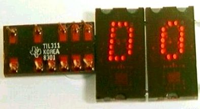
Any ideas?? I just wanted to share cause I think it's a pretty cool little chip and it kind of matches with the cabinet's LED marquee and of course all of the LED lit buttons. Lastly, Here's a pic of them lit up:


Toonces
« Last Edit: March 10, 2006, 01:03:46 am by Toonces »

SirPoonga

  • Puck'em Up
  • Global Moderator
  • Trade Count: (+1)
  • Full Member
  • *****
  • Offline Offline
  • Posts: 8188
  • Last login:July 20, 2025, 03:37:24 pm
  • The Bears Still Suck!
Re: GPWiz-49 Joystick Mode Numeric Indicator LEDs
« Reply #1 on: March 10, 2006, 04:02:01 pm »
That's interesting.  If I get a gpwiz49 I'd make a lighted instruction card that lights up an icon indicating the mode.

Farmboy90

  • Trade Count: (0)
  • Full Member
  • ***
  • Offline Offline
  • Posts: 294
  • Last login:June 26, 2006, 12:15:04 am
  • My cab is done... Pics coming soon!!
Re: GPWiz-49 Joystick Mode Numeric Indicator LEDs
« Reply #2 on: March 10, 2006, 04:59:04 pm »
I hate to hijack the thread and ask a question of my own, so please forgive me.  But you have done something I am wondering about so I know you can help answer my question.

You say you have all the p1 and p2 buttons wired to the same led-wiz outputs.  So the p1 #1 button is wired to the same output as the p2 #1 button, etc.

Do you also have the RGB drives?  I was wondering if all you do is simply splice the wires off of the led-wiz and run one splice to one button and the other splice to the second button?  Is it this simple, or do you need new resistors or need to worry about power issues or anything (since two leds are now being powered by the same led-wiz output)?

Thanks!

Major Rock Hardy

  • Trade Count: (0)
  • Full Member
  • ***
  • Offline Offline
  • Posts: 261
  • Last login:April 29, 2013, 06:51:45 pm
  • xybots rocks!
Re: GPWiz-49 Joystick Mode Numeric Indicator LEDs
« Reply #3 on: March 10, 2006, 05:39:08 pm »
I've tossed around the idea of using these...

I like the idea of using serial control - w/o too much hacking you might be able to hook them up to com2.  Then they would display ASCII.

Toonces

  • Trade Count: (0)
  • Full Member
  • ***
  • Offline Offline
  • Posts: 227
  • Last login:March 04, 2024, 11:25:24 pm
  • I want to build my own arcade controls!
Re: GPWiz-49 Joystick Mode Numeric Indicator LEDs
« Reply #4 on: March 10, 2006, 06:10:41 pm »
That's interesting.  If I get a gpwiz49 I'd make a lighted instruction card that lights up an icon indicating the mode.

Wow, I hadn't thought of that. Very simple idea that would be easy to do and would work really well with my cab. I'll have to give that some serious thought. Maybe I could use Randy's graphic for a template.

Very good idea indeed.

Thanks,

Toonces

Toonces

  • Trade Count: (0)
  • Full Member
  • ***
  • Offline Offline
  • Posts: 227
  • Last login:March 04, 2024, 11:25:24 pm
  • I want to build my own arcade controls!
Re: GPWiz-49 Joystick Mode Numeric Indicator LEDs
« Reply #5 on: March 10, 2006, 06:19:36 pm »
I hate to hijack the thread and ask a question of my own, so please forgive me.  But you have done something I am wondering about so I know you can help answer my question.

You say you have all the p1 and p2 buttons wired to the same led-wiz outputs.  So the p1 #1 button is wired to the same output as the p2 #1 button, etc.

Do you also have the RGB drives?  I was wondering if all you do is simply splice the wires off of the led-wiz and run one splice to one button and the other splice to the second button?  Is it this simple, or do you need new resistors or need to worry about power issues or anything (since two leds are now being powered by the same led-wiz output)?

Thanks!

Yes, that's how I have it wired. I also have the rgb drives. I wired each one seperately then just put both wires for the same legs of the 2 buttons I want to light up in the terminal block. Both LEDs get the signal at the same time. They each have their own resistors and a common 5V bus that feeds all of the LEDs. It's that simple. As far as power, my USB ports are rated at 500ma for the onboard ones and 250ma for the offboard ports (I have no idea why the difference, it's just what windows tells me when I get properties on the USB controllers) and the LEDs are 20ma each, max current. There are a total of 14 LED's on if all are on in a single color. That's 280ma total max current. Well within the 500ma of the port. If you are worried about it you can use an external 5V supply and go higher but you probably wouldn't need to.

Toonces

  • Trade Count: (0)
  • Full Member
  • ***
  • Offline Offline
  • Posts: 227
  • Last login:March 04, 2024, 11:25:24 pm
  • I want to build my own arcade controls!
Re: GPWiz-49 Joystick Mode Numeric Indicator LEDs
« Reply #6 on: March 10, 2006, 06:21:11 pm »
I've tossed around the idea of using these...

I like the idea of using serial control - w/o too much hacking you might be able to hook them up to com2.  Then they would display ASCII.

Not for these particular chips as they have all of the associated circuitry like a decoder and latch built in. These are HEX only displays. You could do that with a dot matrix one or a seven segment model though.