I'm trying to run LEDblinky on my arcade so that I can illuminate only the buttons that are being used. It looks like most of the Ultimarcs that people have posted pictures of use the boards without wiring plugs. My current setup has LED buttons and wiring with 3-wire plugs. Do I need to switch to different buttons and wires or will one of the Ultimarc boards work?
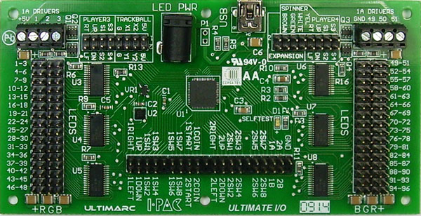
Standard LED controllers like the one in the Ultimatc Ult. I/O apply a fixed positive voltage from an external power supply (LED PWR next to USB) to the anode (+) of the LED/current limiting resistor circuit in the LED button.
Brightness of the LED is controlled by varying the resistance between the Red, Green, and/or Blue channel connected to the LED cathode(s) (-) and ground.
To brightly light an RGB LED with red, the Red channel resistance is set to the lowest possible setting (max. current flow) and the Blue and Green channels are set to the highest possible setting. (no current flow)
LED | LED Button | LED controller
controller
|---- Red LED -------Red current limiting resistor ------ Red channel -------variable resistor ---- ground
5v ----|---- Green LED ----Green current limiting resistor ---- Green channel ---- variable resistor ---- ground
|---- Blue LED ------Blue current limiting resistor ------ Blue channel ------ variable resistor ---- ground
As Vocalitus points out in
this thread, the three wires for your buttons are:
- Data for the button press encoder input
- 5v for the LED
- Ground for LED and button press
DISCLAIMER: The following is theoretical. AFAIK this has not been confirmed working with this hardware. (or even tried)
You
might be able to use those buttons with the Ult. I/O board.
- Connect the data line to the desired switch input (lower center pins on the board)
- Connect the 5v line to the + of the desired LED #. (pins on the far left column, or far right column)
-- Pin numbering on the left is
+, 1, 2, 3, etc. (+ R G B label on bottom of board)
-- Pin numbering on the right is 49, 50, 51,
+, etc. (B G R + label on bottom of board)
- Connect the ground to the desired LED channel. (i.e. Blue channel on pin 3 or 49)
- Configure LEDBlinky to light the buttons max. brightness Blue when in use. This LEDBlinky color must match the color channel that you used in the previous step.
- When the LED lights and you press the button, the voltage applied to the button input will
probably be low enough to trigger an output.
You might be able to do something similar with the Mini-Pac, but you'll need a separate LED controller.
Scott


 Home
Home Help
Help Search
 Login
Login Register

 Send this topic
 Print
Print Topic: Which Ultimarc board for arcade buttons with 3-wire plugs? *pics included* (Read 13970 times)


