Like most of you guys, I have always had a soft spot for racing games. So, since my first buy in 2008 in my spare time I have developed and tested my own solutions to interface racing cabinets to PCs. My love for upright cabinets like Outrun and Chase HQ made me focus on those generic racing cabinets with a "jamma-like" wiring so, in case anyone is wondering:
this is not a new solution to convert a Model 2/3 cabinet. It not even a "unversal" solution for racing cabinets: just my solution to my specific convertion.
It is, anyway, a DIY approach to convert very common (at least here in Italy) racing cabinets and, being sure that the info and solutions adopted could be of some help for someone, I decided to write down some note to share with you

To reassume the project, this PC-to-racing cabinet interface:
- aims at the simplification of the convertion of a "pseudo-jamma" racing cabinet to a MAME/PC racing cabinet
- aims at maintaining the cabinet CRT monitor, with block of potentially dangerous out-of-sync signals and on-board video amplifier for a better picture
- aims at maintaining the cabinet factory controls (wheel, pedal, shifter, buttons)
- allows you to play any game/emulator supporting Xinput
- can handle game outputs (2 rumble signals and 8 generic outs, i.e lamps, additional motors, etc.)
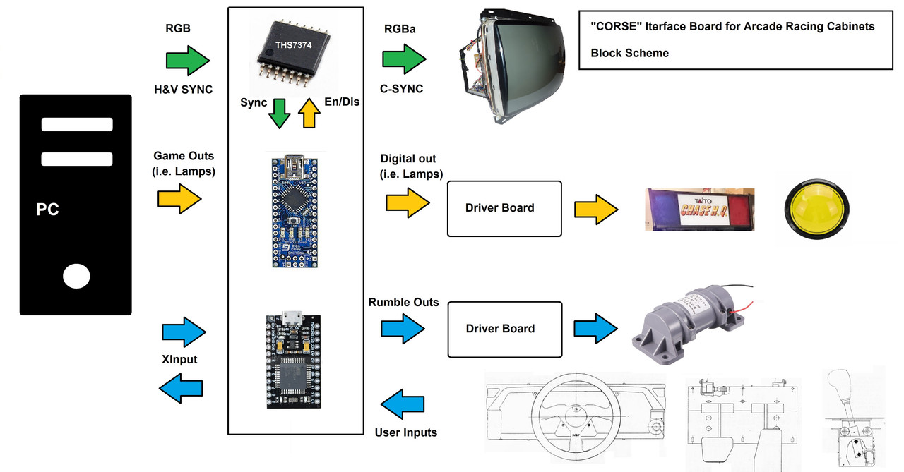
A block diagram of the whole project could help figuring out what the interface is made up of:
 Hardware
The hardware maily consists of two arduino boards and a video amplifier. Arduino's are a pro-micro (ATmega 32u4) emulating an Xinput device for user inputs and rumble, and a nano v3 (ATmega168P, 5V) for sync frequency check and lamps outputs. The video amplifier is a THS7374 SMD IC, most commonly used in consoles hacking.
I have not included an audio amplifier here so that one can choose the right amp for the cabinet is use. The same is even more true for driver boards (even if I designed a set) as their selection is strictly related to the load to drive.
Separate horizontal and vertical sync signal coming from the PC are turned into composite via a (very simple) onboard circuit.
SoftwareSketches are written by me and rely on open libraries. In particular, Arduino pro-micro/leonardo uses Dave Madison (AKA dmadison)'s
Xinput library to emulate an Xinput controller. This makes it compatible with a whole lot of games and expecially with Boomslang's FF Plugin.
Arduino nano sketch is such that it receives serial messages from softwares like Howard's Mamehooker and send them "to the real world".
PinoutThere's not a standard pinout for racing cabinets, so the jamma thing is limited to power supply, video signals, speakers and some digital input (start button, coin switch, test switch service switch).
This means that, whatever racing cabinet we are dealing with, some solder will need to be melted anyway. This is why I took the poetic licence to place all the other digital inputs on the P1 side of the jamma fingerboard in the hope of a simplification of some sort.
The pinout for CORSE, in particular on the jamma side, is the following:
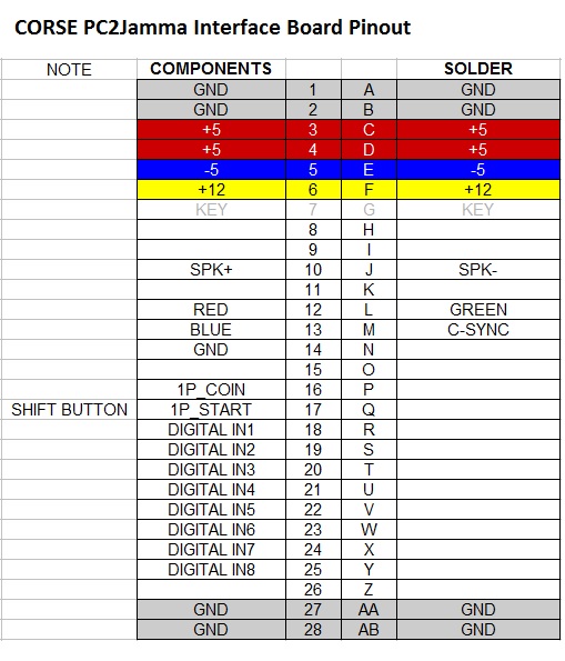
Outputs (lamps, coils, rumble motor/s etc) and analog inputs are kept outside the fingerboard and have dedicated screw terminals. Rumble signals also have their dedicated output terminals.
About analog inputs (wheel, brake and accelerator), only potentiometer based wheels are supported by the current sketch, but it should be possible to implement optical wheels (not an easy task anyway).
Generic outputs are 8 in total, so you can handle a start lamp, two flasher lamps (I love chase HQ), and another 5 lamps (who said "view lamps"?
), but you are not limited to lamps! Motors can also be handled, depending on the software sending data to "Corse".
Please, notice that no driver board are installed onboard! An adeguate driver board is in the need for any of the loads you want Corse to drive.
I could have placed outputs on the Player 2 side of the fingerboard eventually (left unused in the pinout), but outputs in a cab often are not factory (i.e. in my case the start button LED and rumble motor) and screw terminals are more practical than soldering on the fingerboard.
UtilitiesOn the utilities side, I placed a PANIC! button to software force-disable rumble. This is to deactivate rumble any time something weird happens while testing new softwares or settings (...and it always happens!).
There's also a jumper to force-enable the video amp while debugging video modes or the video circuit itself.
The three trimmers for RGB colors are there because if you are using an arcade monitor, a value of some hundreds ohm (200 is my optimum) is generally ok at the output of the video amp (at least with Hantarex and similar monitors...). If you are instead using a TV-CRT, the resistor value must be lower (75 ohms).
Also, there are differencies from monitor to monitor due to ageing, connections, etc. etc. and those trimmers are sufficient to take care of such differencies.
This board, like any commercial product out there, cannot force the VGA video signal to CGA or EGA resolutions by itself, but special softwares like soft15KHz or CRT emudrivers are needed.
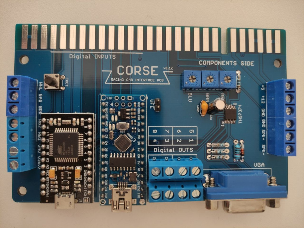
I have a first prototype of the board populated, just to show you


 Home
Home Help
Help Search
 Login
Login Register

 Send this topic
 Print
Print Topic: CORSE - my Racing Cab Interface Board (Read 7142 times)


