I'm currently trying to convert an old "prosumer" monitor for arcade use. It's the Proton 602M, and in its day it was a very high-end monitor. I got this one from the original owner, who barely used it since the 1980s, and the tube and chassis are still in absolutely fantastic shape for their age. It apparently has been serviced for a recap at least once in its life, so it was very well cared for. This monitor also had a special power supply with drive and deflection circuits built separated from eachother, with a crazy-weirdo split flyback like nothing I've seen before. As you can see, the convergence and geometry are still pristine. Hence, why I'd love to build it into an arcade machine.
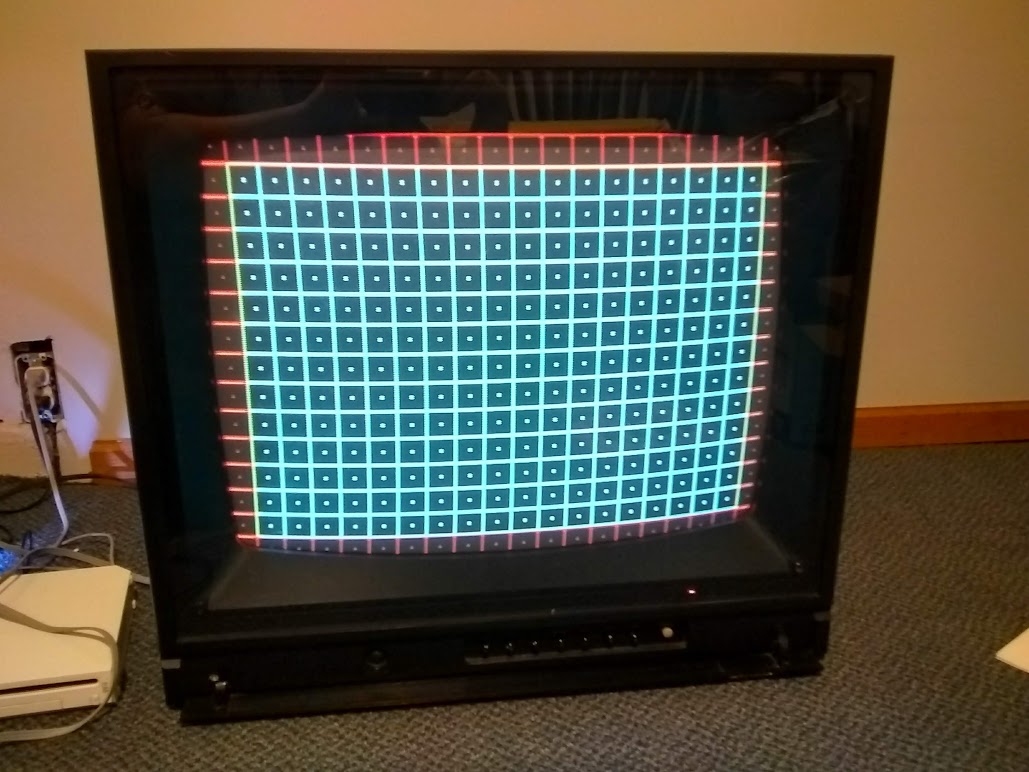
Unfortunately I'm having issues with modding it for RGB, and I'm hoping some folks here could help or at least point me in the right direction. When I have my signals hooked up, it looks like this:

Right now I have a Neo Geo MV1C mobo hooked up to it, and the RGB signals are attenuated with 240 ohm resistors, and the sync is attenuated with a 1k resistor. I am currently inputting sync through the composite input jack, and RGB are connected to some convenient test points labeled TP-54R, G, and B. You can see them on these circuit diagrams.
Annotated Circuit Diagram. Red and Green highlights indicate RGB input test points, yellow indicates various sync injection points I tried. Note that only sync injection point 1, the composite input, had any effect at all. All other injection points seemed to produce no image at all.
Block DiagramMore circuit diagrams for daughter boardsAdditional Photos:
https://photos.app.goo.gl/cF9RUwfsmknwD5LK9Worst case scenario, I would like to at least reuse the tube and yoke, because it's in really great shape. I think it's a CR-23 neck, and the yoke resistance reads 1.1 ohm on one pair, and 8.5 ohm on the other. Would it be possible to completely replace the chassis with an arcade chassis, and if so, which one would be a good pick?
Thanks in advance for the help.
EDIT:

Split flyback, notice the C-shaped part on the left, and the screen and focus controls in a separate potted compartment with HV leads between. Ridiculous power supply to the right.

Neck Board


 Home
Home Help
Help Search
 Login
Login Register

 Send this topic
 Print
Print Topic: Proton 602M- woes of adding RGB (Read 1836 times)


