The Grayhill 04A joystick is often used for mini builds, but the big problem with it is that it has no mounting plate to allow for easy repair/replacement if it is damaged.
Le Chuck glued the sticks in place for his
Gauntlet Micro (no easy maintenance) and Yvan256 came up with
this idea for his CNC64 controller. (need a CNC machine to do it right)

This design is intended to be much easier to hand-build and repair.
Use a piece of .1" perfboard with an intact 15 x 15 hole grid. (Cut on the 16th-hole line.)
Drill the center-most hole in the perfboard out to 3/8".
Clean up any rough edges with a needle file and/or an X-Acto knife.
Use a black Sharpie/paint/nail polish to color-match through and around the center hole on the perfboard to the joystick.
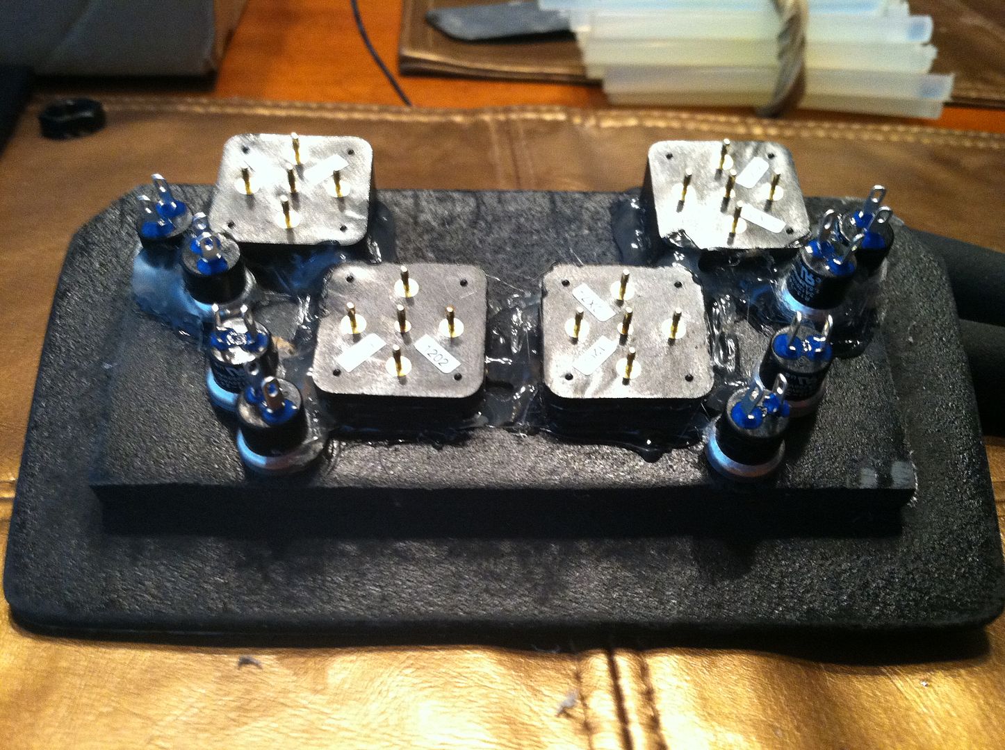
To mount the joystick to the perfboard, use .020" stainless steel Safety Wire -- sometimes called Locking Wire.

The base is .84" wide, which will make it fit tightly when you wrap the wire around it.

To prevent accidental shorts, strip 4 lengths of insulation .8" long off some spare 22 gauge wire.
Green (insulated) lines on the diagram are on the bottom/pin side, red dotted lines are on the top/handle side.
Last hole/loose ends are indicated by the blue arrows.
Guide the wire as you pull it through to prevent loops/kinks from forming.
Pull it tight at each bend to minimize wiggle room.
 1.
1. Start with an 18" piece of safety wire with one piece of insulation near the middle.
Bend the wire in a tight U-shape around the base of the joystick.
Start to attach the joystick to the perfboard by threading the wire through the perfboard 1 hole right / 4 holes up/down from the exact center.
2. Hold everything close together to prevent slack as you thread through the perfboard 3 holes to the right / 3 holes toward the middle.
3. Thread insulation onto the wires and route them between the insulated segment from step 1 and the base of the joystick.
Thread the wire through the perfboard.
4. Thread through the perfboard 3 holes to the right / 3 holes toward the outside.
5. Thread insulation onto the longer of the remaining loose ends and bend the wire across to the other loose edge.
Use Safety Wire Twisting Pliers to twist the ends into a pigtail and remove any remaining slack. ("Barrel roll" at 1:38)


Caution: Watch out for whipping ends as you use the pliers to twist the wire.
If you're using .020 safety wire, it should have 10-12 twists per inch.
At 10 twists per inch, the distance between "bumps" is the same as from one hole to the next in the perfboard.
If you only need the joystick, a stainless steel wallplate like the one linked in the parts list is a great choice.
In this example, the joystick is going to be part of a mini-admin panel with Exit, Pause, Enter, and Menu buttons -- Coin and Start will be on a separate panel.


E-Switch 320-01e11 series square pushbuttons are used here because they blend with the desired artwork and come in a wide variety of colors.
The difficult thing about using these buttons on perfboard is the pins.

Fortunately, the trick for easily wiring up the Grayhill joystick also works for these if the wire and pin are oriented like this with the flat of the button pin square to the socket and the edge of the pin pressing against the flexible tab.
A quick touch of solder will ensure a long-lasting connection.
If the pin goes into the socket diagonally, it will be too loose.

Make a spacer block from 1/2" MDF or cutting board.
Mark one corner to ensure you can reassemble it correctly if you have to take it apart.

The unusual holes are there to allow wires to feed through.

The spacer block should be the same size as the perfboard.

Spacer block fully seated.

The top cover requires a very precise template.
Start by tracing the screw holes and outline of a blank plastic outlet cover onto a piece of thin cardboard.
Mark the center of each hole and use a straight edge to draw a line between them.
Use a micrometer (calipers) to measure the exact distance between the hole centers and mark the exact midpoint between them.
Carefully drill or leather-punch the screw holes so they align perfectly with the plastic plate.
**WARNING** Do not make these holes any larger than the screws -- any "wiggle factor" will cause problems when transferring the template pattern.
**WARNING**
Insert a thumbtack or straight-pin (largest that will fit) through a piece of perfboard at least 9 holes from any edge.
Use a sturdy corrugated cardboard box as a base and push the tack through the midpoint of the template, impaling it onto the box.
Align the holes in the perfboard with the line on the template so that it is square.
Count 7 holes left and 7 up -- (-7,7) in (X,Y) notation with (0,0) being the center/midpoint.
Insert another tack/pin in that hole.
Use these two tacks/pins to hold the template steady while you mark the other critical points.
Use a third tack/pin to mark the folowing X,Y locations:
(-2,7)
(-2,2)
(-7,2) Upper left button outline.
(-7,-7)
(-2,-7)
(-2,-2)
(-7,-2) Lower left button outline.
(7,7)
(2,7)
(2,2)
(7,2) Upper right button outline.
(7,-7)
(2,-7)
(2,-2)
(7,-2) Lower right button outline.
When you're done the template and corrugated cardboard will have a pattern of holes like this -- red circle = center hole.

Use a straight edge and an X-Acto knife to trim the button outlines.

Test the template with buttons on a piece of perfboard to ensure that it fits perfectly before you transfer the pattern to plastic.
Use screws to align the template.

Carefully trace the four button holes and mark the center hole.
Drill out the center hole with a 7/16" bit.
Chain-drill the button holes with a small bit or use a sheet metal nibbling tool.

Use an X-Acto knife with a fresh blade to carefully shave the button holes barely to the outline.
Add a slight bevel on the underside of the faceplate so the buttons will fit in easier.
Note the green dot to indicate orientation, same as on the joystick and spacer block.

Take your time to hand-fit the faceplate as needed.
I got impatient on the holes for green and blue.

Sharpie + artwork FTW?

The white is from a temporary cardboard spacer.
Before final assembly, any gaps like that should be blacked out.
1/8" spacers will keep the buttons and joystick very low profile.

The rest is pretty straight forward.
The faceplate (gray) is countersunk flush into the face of the panel.
It is held in place with long countersunk screws, lockwashers (red), and nuts. (blue)

Piggybacked onto the extra length of the screws is a second plastic plate with pass-thru holes for the control wires.
It provides support to the joystick/button assembly and is held on by finger-tight nuts. (yellow)
Final installation and assembly will have to wait until the build artwork is finished and the control enclosure is built -- no idea how long that will take.
 Materials:
Grayhill 04A-B01 Bat handle Joystick -
http://www.alliedelec.com/search/productdetail.aspx?SKU=70216782
1-Gang Blank Electrical Handy Box Cover, Plastic
http://www.homedepot.com/h_d1/N-5yc1v/R-202077375/h_d2/ProductDisplay?catalogId=10053
1 Port F and RCA Connector Wall Plate, Stainless Steel
http://www.pimfg.com/Product-Detail/P-C-1
.020" T304 Stainless Steel Binding Wire
http://www.amazon.com/gp/product/B001RBFNEO/Wiring
http://www.paradisearcadeshop.com/jamma-harnesses/301-4-wire-100-header-wiring-harness.html
E-Switch 320-01e11 Series Pushbuttons
http://www.mouser.com/Search/Refine.aspx?Keyword=320.01e11
9" Safety Wire Twisting Pliers
http://www.harborfreight.com/9-inch-safety-wire-twisting-pliers-45341.htmlPerfboard with .1" hole spacing
22 gauge wire for insulation
1-1/2" x 1-1/2" x 1/2" piece of cutting board (Leftover from another project - 1/2" MDF will work just as well)
Flat-head screws and nuts -- sized to sit flush with the faceplate.
Scott


 Home
Home Help
Help Search
 Login
Login Register

 Send this topic
 Print
Print Topic: Grayhill 04a Joystick Mount (Read 2593 times)


