So I have two sets of wires that hook up to the joystick. One that is just black and red and the other has black, red, yellow, ect. If I can understand the color relations in what you told me it makes sense, but then why do I have 2 red and 2 blacks.
Wire colors aren't always the same.
When wiring AC circuits, black is usually hot, white is usually neutral and green is usually ground. (Some countries/regions use different colors.)
When wiring DC circuits, red is usually the operating voltage and black is usually ground.
With signal wires, black is often ground, but not always.
Colors are often repeated. Picture trying to use a different color wire for every input on your IPac.

-----
At first, I thought you had an LS-40 knockoff, but now that I look closer, there appears to be an extra 5-pin connector on yours.
LS-40 with 5-pin connector on right for ground and 4 directions.
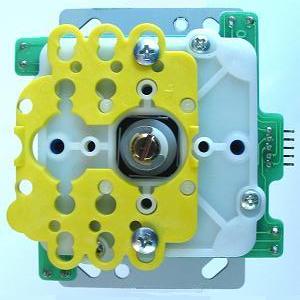
Your stick has a 2-pin connector (probably 12v for LEDs) and
two 5-pin connectors.

Did it come with
any documentation or are there
any markings like "+", "-", "NO" or "NC" on the board near the connectors?
If not, you can still determine which of the 5-wire connectors is tied to normally open (NO) and which is normally closed (NC) -- only reason I can think of why there'd be 2 connectors, unless one is used to light up the joystick when pushed:
1. Strip a little insulation off the ends of the 5-wire harness and connect the wires to ground(black) and the 4 directional inputs on the IPac.
2. Connect the harness to one of the 5-pin connectors on the stick.
3. Launch
WinIPac and set the view to panel mode (shown below) or go to menu -Tools-Test mode (only shows latest/current input)

4. Connect the IPac via USB.
5. When you push the joystick up/down/left/right the blue triangles around the joystick on WinIPac should light up. Press the arrow keys on your keyboard if you're not sure what you're looking for.
6. If only one of the four directions lights up, unplug the IPac from the USB and try to turn the 5-pin connector over so the red wire end is now where the black wire end was, then repeat steps 4 and 5. If none of the directions lights up or all 4 light up at once, skip to step 8.
7. Make a diagram so you can remember later which side of the stick is paired with which wire color.
8. Unplug the IPac and change the 5-pin harness to the other 5-pin connector.
9. Repeat steps 4-8.
10. By this point, you should know which connector and orientation works.
11. Just to be sure the LED voltage input isn't tied to one of the 5-pin connectors, plug the 2-pin harness into the joystick, strip some insulation off the end of that red wire, and connect it to one of the open inputs on the IPAC.
***DO NOT CONNECT THE 2-PIN HARNESS TO A 12v SOURCE (MOLEX) FOR THIS TEST.***
12. Move the joystick around and ensure that the input you connected to doesn't light up in WinIPac. (If it does, that 5-pin connector is for LED lighting)
13. Change the 5-pin harness to the other connector and repeat step 12.
Scott


 Home
Home Help
Help Search
 Login
Login Register

 Send this topic
 Print
Print Topic: Wiring questions (Read 2233 times)


