Main Restorations Software Audio/Jukebox/MP3 Everything Else Buy/Sell/Trade
Project Announcements Monitor/Video GroovyMAME Merit/JVL Touchscreen Meet Up Retail Vendors
Driving & Racing Woodworking Software Support Forums Consoles Project Arcade Reviews
Automated Projects Artwork Frontend Support Forums Pinball Forum Discussion Old Boards
Raspberry Pi & Dev Board controls.dat Linux Miscellaneous Arcade Wiki Discussion Old Archives
Lightguns Arcade1Up Try the site in https mode Site News

Unread posts | New Replies | Recent posts | Rules | Chatroom | Wiki | File Repository | RSS | Submit news


Author Topic: Raiden DX board repair  (Read 7687 times)

0 Members and 1 Guest are viewing this topic.

opt2not

  • Trade Count: (+15)
  • Full Member
  • ***
  • Offline Offline
  • Posts: 6173
  • Last login:April 02, 2024, 07:42:30 pm
Raiden DX board repair
« on: March 08, 2012, 05:27:10 pm »
Don't know if this thread should be stuck here, but here it is. Mods can move it where-ever it needs to go.
I've posted this on a few other sites as well.

I picked up a dead Raiden DX board on the cheap, with the hopes of seeing what I can do to get it working. Though I've repaired a couple boards in the past, I am by no means an expert, and those past repairs were simple stuff like failed audio circuits or faulty chip socketing/swapping.

Figured I should get a post up in case anyone wants to chime in onto what things I can look out for.

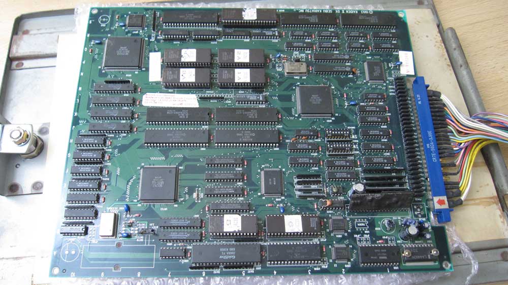
The board was dead-dead, didn't power up at all, black screen, no audio etc... dead.
On top of that, it had evidence that the board was not well stored, but seemed to be sandwiched between other boards. Given the fact that there were scratches all over the place. Check out this cap!

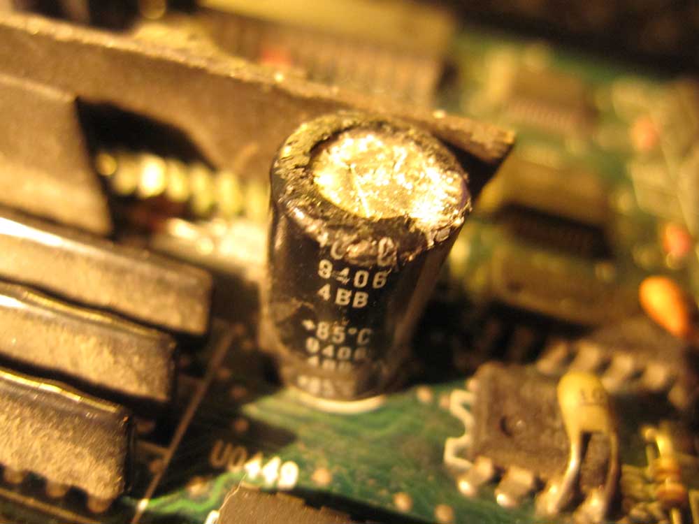
All the caps are like this. In my experience, most of the time capacitors are linked to the audio circuit, and seeing that these were all in the audio section of the board I left them alone till I can get this thing powered.

First things first: Clean the board, look for physical damage.
I took out my trusty magnifying glass and scanned through looking for any kind of blemishes I could find. Primarily looking for broken traces given the amount of scratches.
But the first, most obvious thing I noticed was one of the custom chips had a bunch of legs detached from the board!


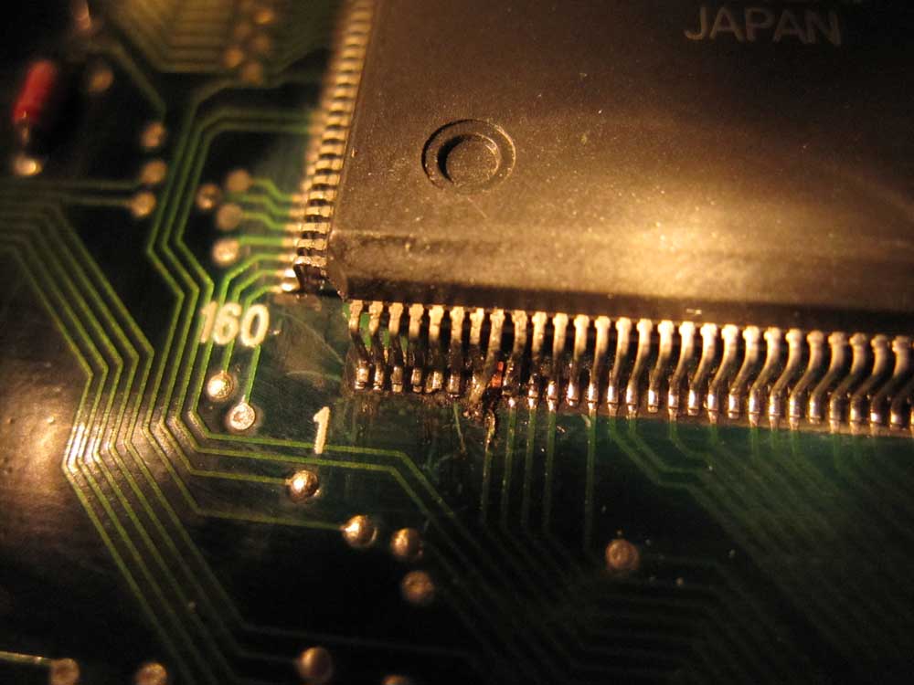
On top of that, one of the traces was ripped. I'm guessing something must have snagged on the legs and got yanked when the board was moved around.
I thought "well that must be the reason it doesn't power up".

So with a little hope, I soldered the legs back as best I could, continuity tested to make sure they were in fact connected and not connected to each-other, then plugged it in and voila!  The game boots! I was ecstatic there is still some life left in this board! But there's no audio, and the sprites are crap.

It seemed like the game was running properly in demo mode.


So the next thing I looked at was the audio, 'cause I'd like to ascertain whether the game logic was indeed running properly, plus I've fixed audio sections on boards before so I was confident I could find something. Lo and behold I did. There was a tiny broken trace on the bottom side of the board that was linked to the audio section (sorry about the blurry pic, it's hard to get an up-close shot of something this small).

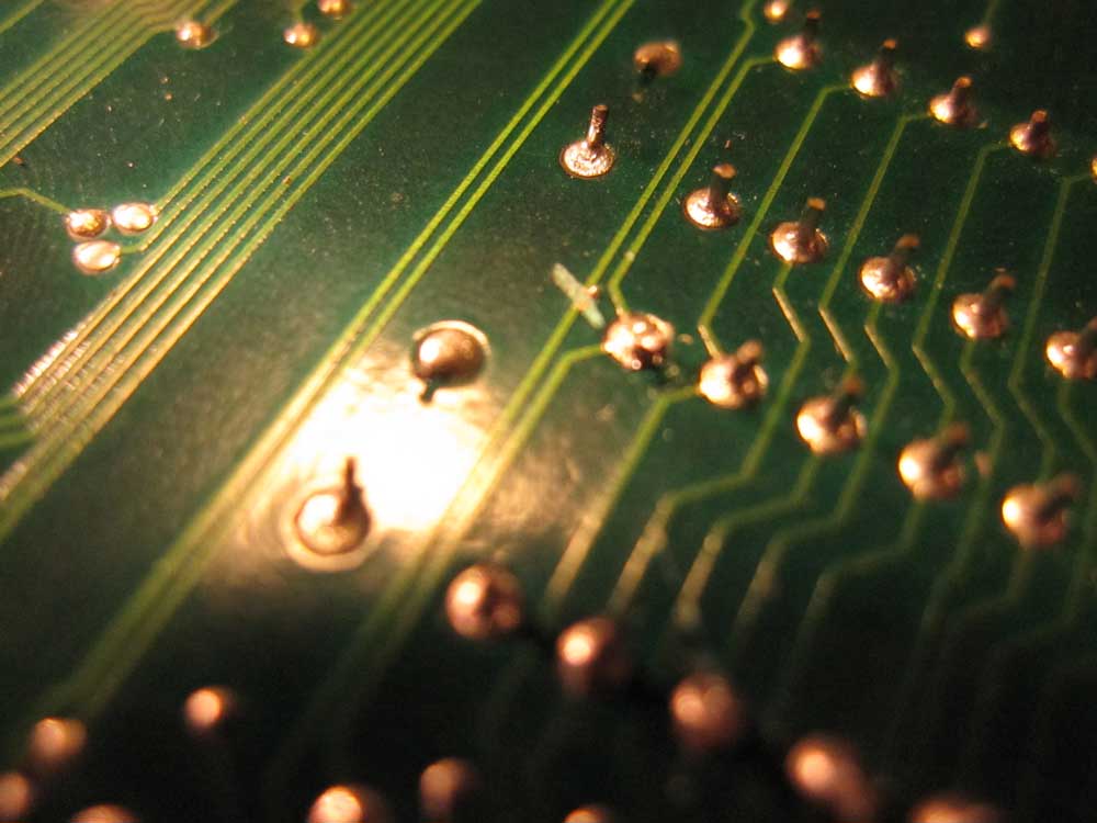
I jumpered the connection as best I could (kinda shanty-like, but it works), powered it up again and the audio worked! Now I can audibly tell that the game logic is intact, I can start a game, select a mission and hear my ship fire, bomb, get destroyed...everything.

Power... check.
Game logic... check.
Audio... check.
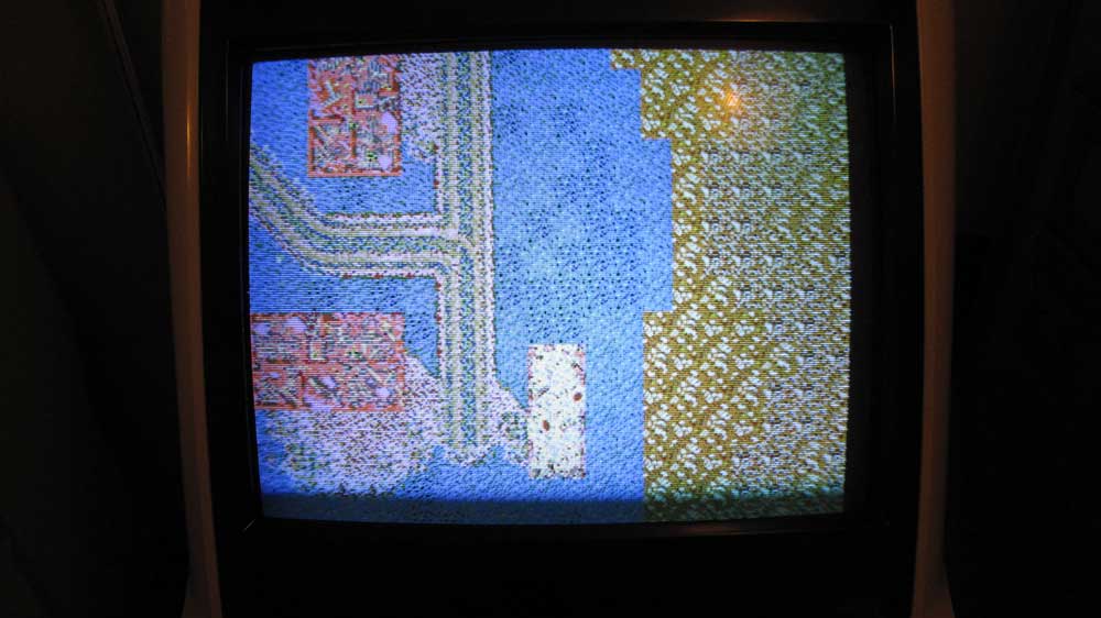
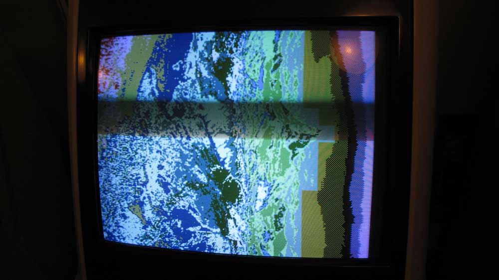
Now the graphic problem...

So I get no ship, bullets, explosions, or title sprites at all. All that is displayed is the background sprites all messed up in colours. I thought there could be two possibilities, 1. sprite roms are bunk, 2. the video ram is crap.
At this point I took out my logic probe and started poking around the rams in the video section.

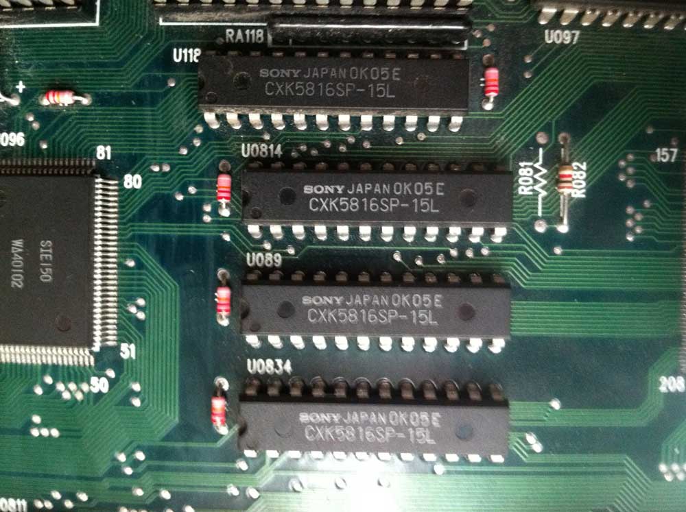
Now I'm not too knowledgeable with logic, but what I found seemed to me that a couple of my rams had floating outputs (nether high nor low and not pulsing?). I connected my working Raiden II board to compare my findings in the video section (since the boards are practically the same hardware, I figured it should be similar in function), found out that 2 out of the 4 rams on my DX board seems suspicious.

OE on one of the suspicious RAM is pulsing fast and neither in high or low. CS is the same. There are a bunch of pins that seem to be floating on this one too.
The other one is low pulsing on OE, and low constant for CS which seems normal (?). But I noticed a low tone fluttering pulse on I/O6 and I/O5, the other RAM aren't doing that. That is why I think this one is suspicious as well.

I went to my local electronics shop where I usually am able to find most components I run into on a board, hoping to just shotgun the rams, but they didn't have any of these in stock.

I'm told that the compatible RAM are:
6116
TMM2015/2016/2018
MCM2018
9116

I'll need the slimline versions, .3" wide and they need a speed of 150ns or faster. I'm going to see where I can source these from.
Any input you guys have would be much appreciated, I really hope I can bring this one back from the dead, its such a great game. Right now, it's on life-support!

ps. I've been referencing this thread a lot, since it's the only in-depth look at repairing this board that i could find on the net.
« Last Edit: March 08, 2012, 06:43:43 pm by opt2not »

IG-88

  • Trade Count: (+7)
  • Full Member
  • ***
  • Offline Offline
  • Posts: 2042
  • Last login:July 06, 2025, 09:21:45 am
  • Posts: 48,764
Re: Raiden DX board repair
« Reply #1 on: March 08, 2012, 08:25:36 pm »
Not any help to you but am glad you are documenting this. It's extremely informative to me. Please keep up the posts!!  :cheers:
"I know what a HAL 9000 is... I was wondering if HAL 7600 was his retarded cousin or something..."
-HarumaN

HaRuMaN

  • Supreme Solder King
  • Global Moderator
  • Trade Count: (+45)
  • Full Member
  • *****
  • Offline Offline
  • Posts: 10328
  • Last login:July 14, 2025, 02:03:34 pm
  • boom
    • Arcade Madness
Re: Raiden DX board repair
« Reply #2 on: March 09, 2012, 09:19:27 am »
Don't know if this thread should be stuck here, but here it is. Mods can move it where-ever it needs to go.

Post hell sounds like a good spot...   >:D

Nice work so far...  I've got 3 PP boardsets to troubleshoot, and it makes me a little crazy working on those things.

Well Fed Games

  • Trade Count: (+6)
  • Full Member
  • ***
  • Offline Offline
  • Posts: 1884
  • Last login:January 07, 2025, 04:42:47 pm
  • Delicious!
Re: Raiden DX board repair
« Reply #3 on: March 09, 2012, 11:00:44 am »
Not any help to you but am glad you are documenting this.  :cheers:
+1!
Completed projects: Pac bartop (Plug & Play), 30th Anniversary Pac cab (MAME), Point Blank (PS1), Centipede (arcade hardware- light restore), VS. Super Mario Bros (arcade hardware- light restore) Tetris Cocktail (SNES), Arcade Classics upright (60-in-1, then MAME), Multi-Raiden (arcade hardware). Pac Man vs.(Gamecube),

Working on: Pinball Re-theme, Homebrew arcade arena shooter

opt2not

  • Trade Count: (+15)
  • Full Member
  • ***
  • Offline Offline
  • Posts: 6173
  • Last login:April 02, 2024, 07:42:30 pm
Re: Raiden DX board repair
« Reply #4 on: March 09, 2012, 05:21:29 pm »
Thanks guys...and Haruman too I guess. :)

Got another thing to check out this weekend. Got a reply on KLOV about someone recently having the same issues on his board before fixing it:
Quote
"I just repaired a DX last week and had the same graphic problems. Besides bent pins on the QFP near the battery area there were a bunch of lifted pins on the QFP near the back edge. Reflowed the entire chip with new solder and the graphics cleared up."
Quote
"Number 8 is the one that had the touching pins on the corner but number 6 is the one that cleared up the graphics problems."

The numbers he's referring to are in conjunction with this image (found off shmups):


Here's a description of what does what:
Quote
Red 1. Custom SEI0200 (related to Green 3)
Red 2. Custom SEI360 (assorted functions)
Red 3. Sound related (ADPCM).
Red 4. Sound related (ADPCM)
Red 5. Custom SEI150 (Sound related)
Red 6. Custom SEI1000
Red 7. NEC V30 CPU
Red 8. Custom SEI252 (Sprite related)


Green 1. '5' is for the sound code, '6' is for the APDCM sound samples
Green 2. Main CPU program code
Green 3. Chars EPROM (ie text are assorted graphics plus scrolling (if removed))


Yellow 1. I/O Related.
Yellow 2. TTL chips for interfacing with the two large black mask ROMs below them for the background graphics
Yellow 3. Sprite RAM (the fourth RAM at the top edge of the yellow ellipse is sound RAM)
Yellow 4. Sprite related

Blue area. Program RAM

In addition to all that, just to the right of Green 1 are two other RAM chips, these are for the colour data

Also, the two RAMs immediately to the right of Red 1 are the RAM for the background tiles and the larger intro animations (ie to do with Green 3).

Now these Customs scare the crap outta me. Mainly because if they're gone, it would kill this project (unless I can find a donor board - either RII or another DX).
I'm going to check the soldering on both of those QFP's, perhaps a re-flowing is in order. We'll see what happens.

IG-88

  • Trade Count: (+7)
  • Full Member
  • ***
  • Offline Offline
  • Posts: 2042
  • Last login:July 06, 2025, 09:21:45 am
  • Posts: 48,764
Re: Raiden DX board repair
« Reply #5 on: March 09, 2012, 06:57:33 pm »
Sorry, newb questions:

1.Where are the QFP's?

2. And how does one check those custom chips? You use a logic probe on those?
"I know what a HAL 9000 is... I was wondering if HAL 7600 was his retarded cousin or something..."
-HarumaN

opt2not

  • Trade Count: (+15)
  • Full Member
  • ***
  • Offline Offline
  • Posts: 6173
  • Last login:April 02, 2024, 07:42:30 pm
Re: Raiden DX board repair
« Reply #6 on: March 09, 2012, 07:05:48 pm »
Sorry, newb questions:

1.Where are the QFP's?

2. And how does one check those custom chips? You use a logic probe on those?
QFP's are those flat surface mounted custom chips. (all the red circled ones)
http://en.wikipedia.org/wiki/Quad_Flat_Package

I would assume to check them you'd have to use a probe on them... but you wouldn't know which pins are what. :dunno

Here's a quote from that repair thread I linked earlier:
Quote
...chips are a pain in the arse, you have no idea what they do, there are no datasheets, you cant even tell which pins are inputs or outputs or bidirectional. All you can do is rule out everything else except the custom, at which point the board becomes scrap if you cant find any other fault.
« Last Edit: March 11, 2012, 08:53:44 pm by opt2not »

opt2not

  • Trade Count: (+15)
  • Full Member
  • ***
  • Offline Offline
  • Posts: 6173
  • Last login:April 02, 2024, 07:42:30 pm
Re: Raiden DX board repair
« Reply #7 on: March 11, 2012, 09:13:07 pm »
SUCCESS!


Ended up re-flowing the solder on a couple of those custom surface mount QFP's I mentioned earlier, plugged it back in and it came out perfect!
Checked the logic on those RAM I was worried about before, and they look all good now. Looks like I didn't need to swap out them after all. Good thing I didn't pull the trigger yet on a purchase.
I now have a fully working Raiden DX board!  :applaud: :D  All sprites are drawing properly, sound is working, coin up, buttons, everything!
I'm going smoke-test it a little while longer and see if there are any more quirks that'll show up.

Big thanks to XianXi over at KLOV that pointed me to exactly what to look at, and everyone who put input in on this fix.

To recap:

Problem 1: Dead Board, didn't power up at all.
Solution: Big QFP near the edge connector (Red 2) had lifted pins off the board. Re-soldered them down and board powered up.

Problem 2:  No sound
Solution: Found a broken trace in the audio circuit. Jumped the connection, audio now works.

Problem 3: Game logic works, but all sprites were missing and background sprites had completely bad colours displayed
Solution: Re-flowed the solder on one of the QFP handling video signals (Red 6 and Red 8)

Cheers all!
 :cheers:

Well Fed Games

  • Trade Count: (+6)
  • Full Member
  • ***
  • Offline Offline
  • Posts: 1884
  • Last login:January 07, 2025, 04:42:47 pm
  • Delicious!
Re: Raiden DX board repair
« Reply #8 on: March 11, 2012, 09:18:38 pm »

I now have a fully working Raiden DX board!  :applaud: :D  All sprites are drawing properly, sound is working, coin up, buttons, everything!


Nice job!  :notworthy:
Completed projects: Pac bartop (Plug & Play), 30th Anniversary Pac cab (MAME), Point Blank (PS1), Centipede (arcade hardware- light restore), VS. Super Mario Bros (arcade hardware- light restore) Tetris Cocktail (SNES), Arcade Classics upright (60-in-1, then MAME), Multi-Raiden (arcade hardware). Pac Man vs.(Gamecube),

Working on: Pinball Re-theme, Homebrew arcade arena shooter

opt2not

  • Trade Count: (+15)
  • Full Member
  • ***
  • Offline Offline
  • Posts: 6173
  • Last login:April 02, 2024, 07:42:30 pm
Re: Raiden DX board repair
« Reply #9 on: March 12, 2012, 06:01:39 pm »
Thanks bro :cheers:
I had this baby running for a good 6 hours yesterday, popping in to have a few games here and there, and it's all good! No problems, no glitches.

It's so rewarding to have spent some time investigating a board, fixing the problems then have it work flawlessly afterwards.

I'm feelin' good enough now to look at my 1942 board that is also completely dead. ;)

IG-88

  • Trade Count: (+7)
  • Full Member
  • ***
  • Offline Offline
  • Posts: 2042
  • Last login:July 06, 2025, 09:21:45 am
  • Posts: 48,764
Re: Raiden DX board repair
« Reply #10 on: March 12, 2012, 07:07:46 pm »
Wow! Great job!! Looks fantastic! One more saved from the scrap pile. This was supposed to take longer so I could learn more.  ;)

Make sure and post up the 1942 board repair as well.
"I know what a HAL 9000 is... I was wondering if HAL 7600 was his retarded cousin or something..."
-HarumaN

emphatic

  • Trade Count: (0)
  • Full Member
  • ***
  • Offline Offline
  • Posts: 2017
  • Last login:Today at 09:30:53 am
  • -"Suck it, Donny!" -"No, YOU suck it.... more".
    • Emphatic's Video Game Collection
Re: Raiden DX board repair
« Reply #11 on: March 14, 2012, 05:04:41 pm »
 :applaud: :applaud: :applaud:

opt2not

  • Trade Count: (+15)
  • Full Member
  • ***
  • Offline Offline
  • Posts: 6173
  • Last login:April 02, 2024, 07:42:30 pm
Re: Raiden DX board repair
« Reply #12 on: March 14, 2012, 06:20:51 pm »
Wow! Great job!! Looks fantastic! One more saved from the scrap pile. This was supposed to take longer so I could learn more.  ;)
Yeah, I think in the future I'm going to go through repairing that broken trace in the audio circuit properly, without jumping the connections with hook-up wire.

But in the case of learning, here's how I re-flowed the solder on that QFP that fixed the video output.
I don't have any fancy equipment, other than a nice soldering iron/station, but for this job I used pretty basic stuff.

- Isoprophenol and a q-tip
- Soldering Station, with a regular tip iron
- Flux (I used a pen applicator, but there are many types of applicators to choose from)
- Solder
- a Braid for cleaning up any solder mistakes
- multimeter with continuity checker
- fine tip tweezers (optional)

1. First I cleaned the QFP pins and pads with a q-tip and Isoprophenol, and applied flux to the base of the QFP pins and the pads they're soldered to.
2. Using my trusty soldering station, I first tinned my iron with a bit of solder...note: you don't need to use a fine tip for this, you need a tip that will hold enough solder to transfer. Also, with fine-tips you tend to have to hold the iron down longer for heat-transfer, which can be damaging to the traces or IC's you're working with.
3. I then carefully touched at each pad that the QFP pins are soldered to, making sure that it heated enough to transfer a bit of solder down to the connection. With the flux, heat-transfer is made easier and I found that it coated the other pins enough that a lot of times I didn't bridge any pins together.
4. For the pins that did get bridged together, I used my braid to soak up some of the access solder. I find that if you tin one side of the braid (the side you are not using to clean up), it makes it easier to heat up quick enough to dab at the access solder. You don't want to have the braid touching the soldered area too long. In this case use Braids with caution because you don't want to have it stick to any additional pins in the area that you're cleaning up.
5. Then used my tweezers to carefully lift the pin away from it's neighbouring pin and pad, and try to soak up any solder that may be bridging the pads. Luckily I only had 2 instances where I had to do this.
6. After each pin was successfully re-flowed, and all access solder cleaned up, I checked each pin with its neighbour with my Multimeter's continuity setting to make sure I didn't have any connected. *There are some pins that are supposed to be connected (I think internally to the QFP), so for me it was easy to check because I have a Raiden II board that has the same QFP's to refer to.
7. Once verified with my Multimeter, again with a q-tip and Isoprophenol I cleaned up the existing flux and surrounding area of the QFP

That's it!
I'm sure there is a better way of doing this, but given my limited soldering equipment and skill level, I made due the best I could.

Hope this helps!

Make sure and post up the 1942 board repair as well.
Will do.
I've got a semi-large art commission to complete at the moment, but after that's done I'm going to take a look at that board and see what the deal is. 1942 has a bit more basic components than these Seibu boards (less custom chips), and repairs for this board are written up all over the net. So I'm hopeful. ;)