Main Restorations Software Audio/Jukebox/MP3 Everything Else Buy/Sell/Trade
Project Announcements Monitor/Video GroovyMAME Merit/JVL Touchscreen Meet Up Retail Vendors
Driving & Racing Woodworking Software Support Forums Consoles Project Arcade Reviews
Automated Projects Artwork Frontend Support Forums Pinball Forum Discussion Old Boards
Raspberry Pi & Dev Board controls.dat Linux Miscellaneous Arcade Wiki Discussion Old Archives
Lightguns Arcade1Up Try the site in https mode Site News

Unread posts | New Replies | Recent posts | Rules | Chatroom | Wiki | File Repository | RSS | Submit news


Author Topic: Fake optical rotary joystick? *** DONE !!!  (Read 9881 times)

0 Members and 1 Guest are viewing this topic.

abaraba

  • ---Perm Ban---
  • Trade Count: (0)
  • Full Member
  • ***
  • Offline Offline
  • Posts: 138
  • Last login:July 30, 2011, 08:42:58 am
Fake optical rotary joystick? *** DONE !!!
« on: December 01, 2010, 09:03:45 pm »
I do not have any rotary joysticks, so I'd like to wire left/right rotation to two buttons, somehow. On 'Caliber 50' PCB there is pin marked "Loop1" and pin "Loop2", meaning "clockwise" and "anticlockwise" I think, but when you connect them with ground pin nothing happens. Loop24 joystick takes 4 wires, 2 for Loop1 & Loop2 signal pins, and 2 for power line pins +5v & GND, so I am tempted to connect Loop1 or Loop2 pin with +5v instead of GND and see if that might rotate the character, but they say it's always best to ask (first), so - does anyone know, or can measure, what kind of signal is produced by optical rotary joysticks such as Loop24? Is it digital, analog, encoded as serial signal like PC mouse, or whatever, and how to fake it?
« Last Edit: December 04, 2010, 05:55:24 am by abaraba »
---Perm Ban, again---

Ed_McCarron

  • Nothing worse than Picard issuing the self destruct order and the next thing you know it your apartment blows up.
  • Trade Count: (0)
  • Full Member
  • ***
  • Offline Offline
  • Posts: 2404
  • Last login:June 20, 2022, 02:33:39 pm
  • Get your mind out of the gutter. THIS is a dongle.
Re: Fake optical rotary joystick with buttons? (Caliber 50/Loop24)
« Reply #1 on: December 01, 2010, 11:15:44 pm »
Quadrature output?  More like the encoder on a mouse axis than the serial output.

Just a guess.
But wasn't it fun to think you won the lottery, just for a second there???

abaraba

  • ---Perm Ban---
  • Trade Count: (0)
  • Full Member
  • ***
  • Offline Offline
  • Posts: 138
  • Last login:July 30, 2011, 08:42:58 am
Re: Fake optical rotary joystick with buttons? (Caliber 50/Loop24)
« Reply #2 on: December 02, 2010, 03:38:31 am »
MAME calls it "Analog Dial", and I think it would be simplest and fastest solution if there was no any serial encoding, but simply variable resistor like with PC analog joystick, say zero ohm=no rotation, 50ohm=180 and 100ohm=359 degree rotation. That would also make it easier for me to make my own rotary joystick from practically any joystick whose stick can be rotated by using a simple potentiometer. I just hope someone who actually owns this joystick will come along with some facts before my temptation makes me start blindly connecting those pins.
---Perm Ban, again---

SavannahLion

  • Wiki Contributor
  • Trade Count: (+1)
  • Full Member
  • ***
  • Offline Offline
  • Posts: 5986
  • Last login:December 19, 2015, 02:28:15 am
Re: Fake optical rotary joystick with buttons? (Caliber 50/Loop24)
« Reply #3 on: December 02, 2010, 10:31:22 am »
Checked the manual yet?

Nvm I'm an ass. I thought the manual would have the schematic. It does not. Well KLOV lists the Loop_24 as optical rotates. That makes sense with four wires. An analog rotor would have three, would it not?

+1 to Ed's guess but I would test/verify first.
« Last Edit: December 02, 2010, 10:55:37 am by SavannahLion »

abaraba

  • ---Perm Ban---
  • Trade Count: (0)
  • Full Member
  • ***
  • Offline Offline
  • Posts: 138
  • Last login:July 30, 2011, 08:42:58 am
Re: Fake optical rotary joystick with buttons? (Caliber 50/Loop24)
« Reply #4 on: December 02, 2010, 07:02:51 pm »
Yes, I hope they would not call it "optical" if it was "analog".

So one "loop" pin is DATA and the other is CLOCK then, just like mouse, which makes it a "spinner".

Why in the world MAME calls this "Analog Dial"? There is nothing analog there then, it would be serially encoded digital signal. Curiously also, in their implementation instead of position analog displacement determines the speed, huh.


Yes, of course Ed's guess is reasonable, the word "optical" implies "mouse/spinner", however the last part of his sentence is contradicting - that IS actually "serial output" then. All the mice are serial devices, on COM port they used RS232 serial protocol, on PS/2 port they use that serial protocol, and on USB port they use universal serial bus protocol. To wire a mouse/spinner as "parallel device" you would loose resolution and require too many wires. So, what serial protocol does Loop-24 joystick use, is it compatible with arcade trackballs maybe, or some PC mice?

Interestingly, mechanical rotary joysticks are "digital & parallel", in contrast to optical which are "digital & serial", and it actually seems there is no such thing as "analog rotary" joysticks at all, even though it would be the simplest design, having faster communication than "digital-serial" (optical spinner), using less wires than "digital-parallel" (mechanical spinner), while having high resolution of optical spinner, if not better.
---Perm Ban, again---

Ed_McCarron

  • Nothing worse than Picard issuing the self destruct order and the next thing you know it your apartment blows up.
  • Trade Count: (0)
  • Full Member
  • ***
  • Offline Offline
  • Posts: 2404
  • Last login:June 20, 2022, 02:33:39 pm
  • Get your mind out of the gutter. THIS is a dongle.
Re: Fake optical rotary joystick with buttons? (Caliber 50/Loop24)
« Reply #5 on: December 02, 2010, 11:12:06 pm »
Yes, of course Ed's guess is reasonable, the word "optical" implies "mouse/spinner", however the last part of his sentence is contradicting - that IS actually "serial output" then. All the mice are serial devices, on COM port they used RS232 serial protocol, on PS/2 port they use that serial protocol, and on USB port they use universal serial bus protocol. To wire a mouse/spinner as "parallel device" you would loose resolution and require too many wires. So, what serial protocol does Loop-24 joystick use, is it compatible with arcade trackballs maybe, or some PC mice?

When I hear serial, I think RS-232 or the like -- data bits, stop bits, parity -- something async...  Not a synchronous pulse stream.

My next guess is you're not going to plug it into any port you'll find on a PC.

This is what I'm referring to.

http://en.wikipedia.org/wiki/Rotary_encoder#Incremental_rotary_encoder
But wasn't it fun to think you won the lottery, just for a second there???

SavannahLion

  • Wiki Contributor
  • Trade Count: (+1)
  • Full Member
  • ***
  • Offline Offline
  • Posts: 5986
  • Last login:December 19, 2015, 02:28:15 am
Re: Fake optical rotary joystick with buttons? (Caliber 50/Loop24)
« Reply #6 on: December 03, 2010, 12:28:27 am »
Wow... methinks you over analyzed that a bit. Just put aside what you know about pcs. You're working with underlying technology. Not that that wrapper ---steaming pile of meadow muffin---.

abaraba

  • ---Perm Ban---
  • Trade Count: (0)
  • Full Member
  • ***
  • Offline Offline
  • Posts: 138
  • Last login:July 30, 2011, 08:42:58 am
Re: Fake optical rotary joystick with buttons? (Caliber 50/Loop24)
« Reply #7 on: December 03, 2010, 02:28:20 am »
When I hear serial, I think RS-232 or the like -- data bits, stop bits, parity -- something async...  Not a synchronous pulse stream.

My next guess is you're not going to plug it into any port you'll find on a PC.

This is what I'm referring to.

http://en.wikipedia.org/wiki/Rotary_encoder#Incremental_rotary_encoder

Interesting. I had no idea there is such thing as "Rotary encoder", while this thing is obviously very well defined and categorized as consumer product. It's news to me potentiometer is then also a type of "rotary encoder", but it is only one of several such 'analogue' devices, where I never heard of others like synchro, resolver, and rotary variable differential transformer. Cool.


So, "quadrature encoding" is just a simple serial (digital) protocol, however I again do not see why the signal could not be translated to analog instead, even if optical encoder stuff is there already. Analog encoding is instantaneous, linear and absolute, it is coded, transmitted and de-coded faster than any serial encoding, where resolution/precision is almost truly "infinitely divisible" or unlimited/continuous aka 'analog', it's the simplest, fastest and most precise way to communicate information, though perhaps subject to higher signal noise during transmission.


In any case, is "quadrature encoding" the same protocol used by arcade trackballs?
« Last Edit: December 03, 2010, 02:36:07 am by abaraba »
---Perm Ban, again---

abaraba

  • ---Perm Ban---
  • Trade Count: (0)
  • Full Member
  • ***
  • Offline Offline
  • Posts: 138
  • Last login:July 30, 2011, 08:42:58 am
Re: Fake optical rotary joystick with buttons? (Caliber 50/Loop24)
« Reply #8 on: December 04, 2010, 05:52:41 am »
Got it working, it is "quadrature encoding" after all, which is great, wooohoooo!

Only now I understand this sentence:
- "Quadrature output?  More like the encoder on a mouse axis than the serial output."

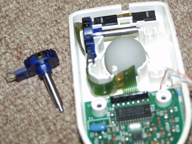
That is exactly it, thank you Ed_McCarron! It turns out every mouse is actually a combination of 'arcade encoder circuit' (quadrature encoding) and 'serial protocol encoder IC'.  And so, $0.10 old mice contains everything you would ever need to build your own rotary joysticks, whether to work with actual game PCB or MAME.

SUMMARY:
a.) arcade trackballs and spinners circuits are simple 'quadrature encoders'

b.) the simplest PC mouse is practically: 2x 'quadrature encoder' + "OptiPac"


In other words, this "quadrature encoder" is there (in spinners, trackballs, mice...) not so much as a "choice" as it is underlying mechanical/digital principle of all these types of encoders. It is there to distinguish between clockwise and anticlockwise direction, but if the direction was not important it will all come down to simply counting impulses - "light goes on, light goes off..."


In my test I could use optical just as well, but this mous also had a mechanical encoder wheel for the scroll-wheel button and that required a bit less soldering to wire up. Basically, you could even make it spin if you took +5V through two wires and "drummed" over pins Loop1 & Loop2 (A & B) in this rhythm:


What constitutes quadrature encoder?


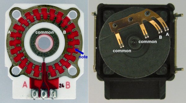
It can be optical and mechanical, but not not like "mechanical rotary joystick". If mechanical, then it is a single part in itself, that looks very much like potentiometer, has 3 legs: on one leg it gets +5v and on the other two (say A & B) it passes this +5v as the wheel turns and brushes touch "off-phase" contact-teeth inside, where rhythm "A-B-A" would mean clockwise, and "B-A-B" anticlockwise, or something, but in any case that is all there is to it, the game PCB does "de-coding", i.e. counting, and all the rest.


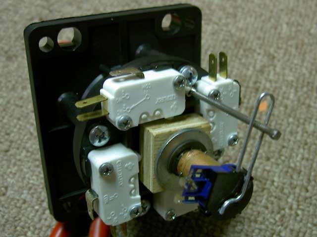
http://www.trimoor.com/rotary_joystick/

That's not mine btw, I found that web-page after everything else, but in any case it is similar to how my mechanical encoder looks like, and exactly what I am going to do with my joysticks now. I will also keep the rest of the mice to make PC/MAME adapter (OptiPac) for this new "ARCADE" spinners of mine.


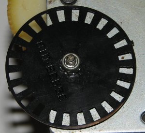
...and, the optical 'quadrature encoders' are made of 3 components:
- slotted wheel
- emitter diode (2 legs)
- 2x receiver diodes (3 legs)


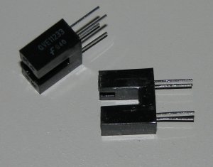
Yes, there are actually two receivers behind each wheel, that's why 3 legs on that one electrical component and what "quadrature encoding" is all about. Depending on the direction of rotation one sensor will get light before the other, and so we again have the same result as with mechanical encoder from above, where +5v comes to pins A and/or B either as "A-B-A" or "B-A-B" rhythm. -- The rest of the mouse is the same thing as "OptiPac", it's encoder IC that counts and converts these +5V impulses into PC serial protocol packets.


EDIT... heh, it's all explained here in greater detail:
- Everything you always wanted to know about optical arcade controls,
but were afraid to ask:
http://www.zumbrovalley.net/readpost.php?artid=1

This was incredibly simple information, which makes it all more surprising why is it not more obvious/documented/underlined.
« Last Edit: December 04, 2010, 08:37:12 am by abaraba »
---Perm Ban, again---

bkenobi

  • Trade Count: (+1)
  • Full Member
  • ***
  • Offline Offline
  • Posts: 1668
  • Last login:August 16, 2021, 10:41:52 pm
Re: Fake optical rotary joystick? *** DONE !!!
« Reply #9 on: December 06, 2010, 12:03:00 pm »
Ok, so did you figure out a way to have a 2 buttons fake the rotary commands then?  Sounds like it's not feasible without using MAME (which sort of hacks the controls).

abaraba

  • ---Perm Ban---
  • Trade Count: (0)
  • Full Member
  • ***
  • Offline Offline
  • Posts: 138
  • Last login:July 30, 2011, 08:42:58 am
Re: Fake optical rotary joystick? *** DONE !!!
« Reply #10 on: December 06, 2010, 08:48:47 pm »
I do not see any point of wiring buttons to it now since it may very well be easier to make real rotary joysticks instead, but I did discover I can make it spin by connecting A & B (loop1 & loop2) pins to +5v somewhat randomly. I guess a button circuit that will pass signal to one pin with slight delay would spin it, direction depending on which pin got the signal first.

In MAME it is default hack to have keys/buttons assigned to analog as well as spinner/trackball controls. The mystery remains why they categorize the later under "Analog Dial" since there is nothing analog about them, and why does analog displacement determines the speed of rotation and not actual position, i.e. 'degrees of rotation'.
---Perm Ban, again---

Gray_Area

  • -Banned-
  • Trade Count: (+1)
  • Full Member
  • ***
  • Offline Offline
  • Posts: 3363
  • Last login:June 23, 2013, 06:52:30 pm
  • -Banned-
Re: Fake optical rotary joystick? *** DONE !!!
« Reply #11 on: December 14, 2010, 04:22:27 am »
I comes to mind a flight stick and spinner might be workable, though you'd probably wear your finger and thumb out on the trigger and thumb button.
-Banned-

Ed_McCarron

  • Nothing worse than Picard issuing the self destruct order and the next thing you know it your apartment blows up.
  • Trade Count: (0)
  • Full Member
  • ***
  • Offline Offline
  • Posts: 2404
  • Last login:June 20, 2022, 02:33:39 pm
  • Get your mind out of the gutter. THIS is a dongle.
Re: Fake optical rotary joystick with buttons? (Caliber 50/Loop24)
« Reply #12 on: December 14, 2010, 10:33:34 pm »
Only now I understand this sentence:
- "Quadrature output?  More like the encoder on a mouse axis than the serial output."

That is exactly it, thank you Ed_McCarron!

Make a note, world.  I did something useful. :)

Glad it's working out.
But wasn't it fun to think you won the lottery, just for a second there???