Main Restorations Software Audio/Jukebox/MP3 Everything Else Buy/Sell/Trade
Project Announcements Monitor/Video GroovyMAME Merit/JVL Touchscreen Meet Up Retail Vendors
Driving & Racing Woodworking Software Support Forums Consoles Project Arcade Reviews
Automated Projects Artwork Frontend Support Forums Pinball Forum Discussion Old Boards
Raspberry Pi & Dev Board controls.dat Linux Miscellaneous Arcade Wiki Discussion Old Archives
Lightguns Arcade1Up Try the site in https mode Site News

Unread posts | New Replies | Recent posts | Rules | Chatroom | Wiki | File Repository | RSS | Submit news


Author Topic: Vicious's First Arcade CP  (Read 5179 times)

0 Members and 1 Guest are viewing this topic.

ViciousXUSMC

  • Trade Count: (0)
  • Full Member
  • ***
  • Offline Offline
  • Posts: 213
  • Last login:July 28, 2009, 10:25:53 am
Vicious's First Arcade CP
« on: February 10, 2009, 05:28:22 pm »
This is my first project ever, I am treading into new territory with some tools, equipment, and I am working in a house full of kids with little time or work space.

Prime Objective: To build a arcade control panel to enjoy authentic arcade controls like I used to do when I was younger in the arcades.

Goals:
> Working on a super limited budget, I decided I could do this cheaper & better on my own than buying a pre-fab product like the X-Arcade so a main goal was to be cheap.
> Space saving, My house is just full of kids and toys I am so jammed in my house that I do not even have a real computer desk/chair combo.  My desk is in the corner and my bed is next to it and acts as my chair.

Overview:

So with my goals in mind I had what I thought a brilliant idea.  I have no space for a cabinet nor the money to build one, I do not even really have a place just for a portable CP, so the idea I had one day when looking at my desk is how much it already looks like some sort of arcade cabinet.


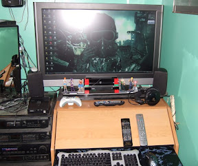
The keyboard tucks under that overhang and that overhand is while slightly a too much of an angle just a flat surface just crying out to be modded into a CP when I got the idea.  So this means no money on materials and no extra space taken up by it.  A perfect fit for the goals I had in mind.

Planning:

So I am a good google person, I find resources well (like this forum) and can learn things fast, so I learned how to do this with no prior knowledge.  The first major obstical was finding what stores sell this stuff.  I found Ultimar.com first, followed by groovygamegear.com.  This also generated my first major desision, the keyboard encoder to use.  I only knew of from those stores and from research the I-PAC and the Key-Wiz and thats about it.  I ended up going what seemed the most logical route and got the I-PAC Value since it was cheapest, and had free shipping.  Its a great encoder it looks like and would just be a perfect fit for a mame setup.

However looking back only a weeks worth of time, I had wished I had known there were many more options out there.  First and foremost I decided at some point a few days ago that I wanted to make a better return on my investment and use this CP not only for Mame stuff but my consoles as well.  I really loved playing my MVC2 on Dreamcast back in the day and it just does not emulate as well as it plays on the system.  So I started having to do major research on how to do this based on my I-PAC setup.  I could have saved myself a lot of trouble and money by knowing about some of these encoders instead.

The Cthulhu Board - Why? Because it does PC & PC3 so it has one system already tied in to save me the trouble.  I do not have a PS3 but this for $5 more would have been a great upgrade to the I-PaC

The X-Arcade BYOA - Why? Because its also a sound encoder from what I can tell and for only $20 you can buy almost any console adapter pre-made for you!  This would have been very easy and cheap for me.  Opinions on X-Arcade stuff are mixed though.

The UPCB (Universal PCB) - Why? Another really awesome solution that attempts to be modular and allow you to easily use almost any console with the encoder and again not expensive.

So what do I do?  Well I did the research and found that you can wire more than one encoder to the CP but you just have to make sure not to have both systems pluged in at the same time.  This is a problem for me since my PC connection will always be on and connected.  So my solution was to totally redo my build idea to this modular system, but my ultra budget system suddenly became very expensive and the skill level and time to make it also just went up many times.

Original Build Costs:
1x Happ Competition Joysticks (About $12 shipped on ebay)
7x Happ Competition Buttons (About $15 shipped on ebay)
1x Drill Bit for holes in desk (About $10 from Lowes)
Wire, Crimps, Crimp Tool (About $25 from Radio Shack)
1x A-B USB Cable (About $4 on Monoprice.com)

So total cost for my MAME only build was about... $50-$60, thats expensive to me but its an investment so I was ok with it, and it was less than the best alternative the X-Arcade.

Deeper into the research though I started to find the catch 22 here and there that made me have to get more things.

> Mounting Hardware for the Joysticks About $8
> Router to recess the joysticks for correct height ($35 cheapo mini router on Harbor Freight)
> Vinyl to make the desk look more "arcade like" and to cover the hole if I top mount the joysticks

Then to do the modular setup I found out I need a ton more stuff.

> Multiple DB25 Cables (About $15 Monoprice)
> Multiple DB25 connectors (About $8 Digikey)
> A DB25 Selector Switch ($15 Monoprice)
> Solder Stuff (I will need a solder station probably like $20)
> Project boxes to put the adapters in ($10)
> Terminal Blocks ($10)
> Dreamcast Controllers ($20)
> DB25 Terminal Block ($25)
> Flush Trim Router Bit ($15)
> Plexi for overlay (not sure if I will do this yet)

So roughly just to add the ability to play my 1 dreamcast game I love... I think its going to cost me like another $80 to $100??? Thats what it looks like and not to mention add a lot of room for error if my skills are not up to par or cant find the right equipment/parts. (I need help with digikey.com part #'s for the DB25 connectors that you can solder to)

So my cost is now way more than the X-Arcade and I have no promises that it will work well, but in exchange the system just got a big upgrade to a modular setup that will allow me to add other consoles to the CP with relative ease down the road, and when/if the time comes to turn this into a full cabnet one day, I will have a head start in making it go together easy, or to have a stand alone CP that I can use in different places for different systems.


Build Log:

So the above picture was just the desk after I cleaned it up some, you can see the black marble vinyl cover on the keyboard drawer probably.  I was board or impatient and had to see what that stuff was like so I applied it to the keyboard area to see what its like.  I ended up really liking it.  It has a good texture, it looks good, it was cheap ($5 on ebay) and so I though it was a good choice to add this to my CP for a bit more flair.

Problem is shortly after I was like wow, it looks bad just with the keyboard like that, I need to do the CP board too... So thats exactly what I did, I didnt think till after the fact that it may get messed up when I drill the holes or if i top mount the joysticks.  However I had some left and could cover those spots up pretty easy.

The Joysticks got here first from Ebay got them from Tornado Terry for like $8.70 each, it was like $8 S&H for the first one but only like $4 for an additional one.  This was a big turning point for me as my Son started to really get into the gaming thing lately and I see myself reliving my childhood through him and I realized hey that I-PAC supports 2 players and the bigger cost here is S&H not the product so I may as well get 2 of them.

So I made the decision here to upgrade my setup from 1 player to 2 players

The Buttons were the same way, from the same seller it was like $.50 for each button until you got past 10 then it was a flat rate.  So it made sense to upgrade my order to 14 buttons.

There was not much I could do with just the joysticks when they came in,  I sort of eyed them down and saw how they worked and taped it under my desk panel to see how high up I would have to mount it to clear my keyboard when it was tucked in.

A few days passed and the buttons finally came in.

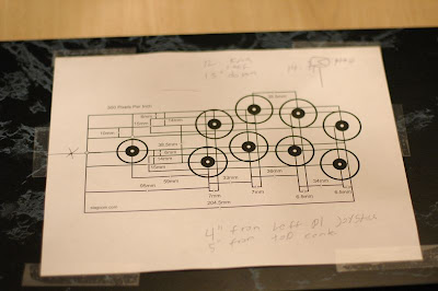
Now with the buttons in hand I started to do a cardboard mock up of the control layout.

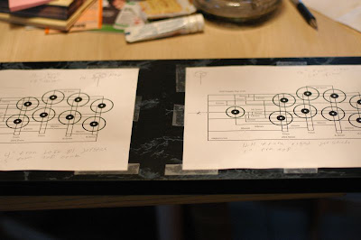
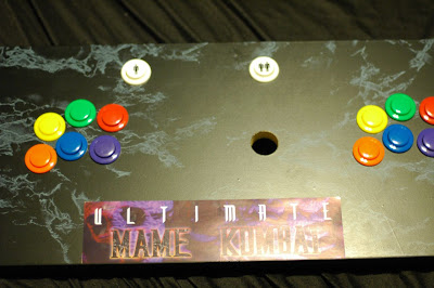
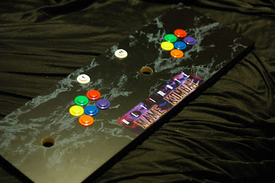
I chose 2 of every color for the buttons.  Original idea was 1 player 2 yellow, 2 green, 2 red in a Street Fighter like layout, with Player 2 using Orage, Blue, Purple.  But I decided that I would use each of one color instead as it seemed to look better and it was more symmetrical.

I found the be all end all site for in scale control templates here: http://www.slagcoin.com/joystick/layout.html

I printed a few of them out and decided I would prefer the Japanese layout to the American one.  (I love Japanese stuff, sort of wish maybe I had gotten Sanwa parts instead of Happ since I did not know of them when I started this, but they are harder to mount and cost more so it was probably for the better)

After getting that figured out, I stared doing major brain work figuring out the rest of my parts and how this is going to go together.  Im still thinking on it for the most part but to help relive some of the stress I went to Lowes and got a 1 1/8" Forerster bit and went into drill my holes today.  I wanted a drill guide so it would be perfect but I didnt have one so I chanced it.

I tried doing this on a fully charged cordless drill and it was almost dead by the first hole.  I ended up walking across the street and asked my nehbor if he had a power drill and he did and let me barrow it.  I am so lucky, thats one tool I did not have to buy!  He gave me some bits to barrow too that I needed because I first drilled a Pilot hole with a small bit before using the big forester bit, it was a good idea too, it kept me straight and also when the big bit tore away the template I still had the guide hole to work with.

Pictures of todays work:

Took the piece of wood out of the desk to be used as the CP and measured with a tape measure where my templates need to be places.  I also moved the joystick out about .5" more than the "far" point the template has, it felt better there in pretend play.


The big test... To see what happens to my vinyl when I drill through it.. Will it tear?

Answer:


Nope!  It seemed like it came out ok.

After about 15min of drilling and cleaning up the dust some (That forester bit did not tear through this stuff nearly as fast/easy as I expected even with a high speed electric drill)


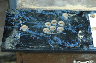
After all the drilling was done I took it inside wiped it off and took it into my bedroom to see how the holes came out.  I could not resist putting the buttons in.  I dont know if I can leave them there with more work to be done or not.  The holes seemed to come out straight from what I can tell,  I do not know whats up with the nuts you tighten onto them, it was very hard to get its threading started, you basically had to thread it off track and after 2 hard turns it would go on track.  This was only for the game buttons, the 2 start/player buttons did not have this problem.

No picture of it but very minor "blow out" on the back side of the board even though I had a board under it when working it was not flush.  It is so minor that it does not effect anything though.

Its starting to look like a CP now!  Even though the project is a far cry from done:


Im almost having second thoughts about the Console idea as its going to cost so much and make it harder and I wont use it often, but its too late to back out now.  Its all or nothing.

So its a game of patience to get the rest of the parts I need.  I need help from more experience forum members probably in finding the parts I need on the web.

I need project boxes, DB24 connectors I can solder too easy, A cheap but effective solder station is probably needed, Terminal blocks, and maybe a few other things.

Wish me and the project luck and stay tuned for updates to the log as I go.


« Last Edit: February 10, 2009, 05:35:44 pm by ViciousXUSMC »

SNAAKE

  • Trade Count: (+29)
  • Full Member
  • ***
  • Offline Offline
  • Posts: 3561
  • Last login:Yesterday at 04:34:10 pm
  • my joystick is bigger than your joystick !
Re: Vicious's First Arcade CP
« Reply #1 on: February 11, 2009, 12:57:45 pm »
people still using marble contact paper?

nice...I just realized Ive been here for like 9 years.. :dizzy:

ViciousXUSMC

  • Trade Count: (0)
  • Full Member
  • ***
  • Offline Offline
  • Posts: 213
  • Last login:July 28, 2009, 10:25:53 am
Re: Vicious's First Arcade CP
« Reply #2 on: February 12, 2009, 03:25:28 am »
lol your now officially the second person to knock on the contact paper.

I dunno whats up with that, I happen to really like black marble, and it would be pretty hard to make it out of the real stuff.

So whats the big deal with everybody hating black marble contact paper?

xonix_digital

  • Trade Count: (0)
  • Full Member
  • ***
  • Offline Offline
  • Posts: 44
  • Last login:February 20, 2016, 04:36:05 pm
  • I am the Milky-Way Commander!!!
Re: Vicious's First Arcade CP
« Reply #3 on: February 12, 2009, 08:24:35 am »
I dig the contact paper!
It's old school.

Can't wait to see the finished product!
   

severdhed

  • Trade Count: (0)
  • Full Member
  • ***
  • Offline Offline
  • Posts: 2975
  • Last login:December 14, 2024, 05:01:52 pm
  • RIP Dinosaur Hippo
Re: Vicious's First Arcade CP
« Reply #4 on: February 12, 2009, 12:50:40 pm »
looking good. that desk looks like it was just begging to become an arcade control panel.  keep those pics coming
Current Projects:      Zak-Man | TMNT Pedestal | SNES Pi | N64 Odroid
Former Projects:     4 Player Showcase | Donkey Kong | iCade

ViciousXUSMC

  • Trade Count: (0)
  • Full Member
  • ***
  • Offline Offline
  • Posts: 213
  • Last login:July 28, 2009, 10:25:53 am
Re: Vicious's First Arcade CP
« Reply #5 on: February 12, 2009, 01:56:55 pm »
Update:

I went to the budget tool store and got the stuff to install the joysticks.

This was the first step that I was not really happy with the outcome.  The plan was just to mount a joystick to see if I liked the depth or if I felt it needed to be routed out for a higher shaft.

So I as usual had to do things one step better than just basic.  In this case that meant buying brass inserts to screw into the board because mdf does not hold up very well after a screw is taken out a few times so just incase I ended up having to take these off I wanted a good permanent hold.

So first thing I did was take a square and mark lines through the hole as centered as possible so that when I put the joystick body over the hole I knew where center was.

Then I penciled the holes so I would know where to drill.

I used a small bit first as a pilot hole and then a bigger bit.  I took the insert and held it up to the bit to see how much depth it has and then put electric tape on the bit to mark my max depth point.

These inserts do not tell you what hole size you need so I just had to eye it.  You would think you want the hole smaller so that the threads sink in good but after doing it I think thats not the case as even a slightly smaller hole resulted in the inserts not wanting to go in and screwing in crooked.

So the very first one when I went to screw it in I guess did not get drilled deep enough and broke the other side out.  Its minor and you cant really see it due to the vinyl paper covering it but it still annoys me.

The other 3 on the first stick went ok but just a bit crooked.

Stick 2 the first 3 went great as I knew I had to make the holes a bit bigger and drill a bit deeper, except the last one.  It refused to screw in straight and by the time I got it to go straight as I was tightening it, it striped out.

So I had to use a wood screw on the last one (the joystick body has 2 holes for each side a life saver)

So my lesson here is that keeping it simple is not a bad idea and just using wood screws would have been cheaper, easier, and probably resulted in a more flush and perfect mount.

Still hands on with the joysticks they feel fine unless I have any problems with them I see no reason to remount them.

Now its back to the waiting game for more of the parts to come in.  I need at minimum for the next step the quick connects and the female DB25 connector to wire the control panel up.

Then after that I need the DB25 cables, the I-PAC, and some project box to wire the PC adapter up to the control panel.

The dreamcast adapter I can take my time on.  I still have to find all the dreamcast stuff to make sure its all in working order.

Pics:

Drawn center lines, and some of the inserts in place


Player 1


Player 2


Full Control Panel

ViciousXUSMC

  • Trade Count: (0)
  • Full Member
  • ***
  • Offline Offline
  • Posts: 213
  • Last login:July 28, 2009, 10:25:53 am
Re: Vicious's First Arcade CP
« Reply #6 on: February 19, 2009, 05:37:56 am »
The I-PAC VE came in.  Being impatient I gave myself a good excuse to install it on the CP and start playing rather than wait and do it right the first time and wire up the DB25 instead.

The reason is since this for now is only going to be a 2 way system modular for PC & Dreamcast there is no reason to go through the trouble of setting it that way until I have my dreamcast up and running and have hacked the controllers and have that working.  At that time I can unhook the I-PAC and wire in the DB25 connectors and send the CP signals to a switch and then put the I-PAC VE in a adapter box and do the same for the hacked DC controllers.

It worked out well, though the first time I mounted and wired the I-PAC I had it a bit too high up not accounting for the fact the USB cord is going to stick out, the drawer still fit on and moved but it was putting some leverage on the PCB and I did not feel comfortable with it.

Great luck on my side I was able to just take out a few wires and it fit between the joystick & buttons and them mount it back down, and all the wires were long enough to make it.

Update: Even greater luck on my side my DB25 terminal board I plan to use on the CP is here and its nice and small it looks like it will swap out with the I-PAC easy, if it was too large I may have had to re-run many of those wires and that means buy more quick connects too as I used every single one of the ones I bought.

Photo Time:

My Final Plans for Wiring:

Waiting on parts to arrive I planed out my pin & wire connections.


I found that I will need separate ground for P1 & P2 to hook up to the hacked controllers.  Lucky the DB25 connection has enough room and I infact still have 1 wire left to add one more button if I wanted.  I was going to make it a coin button but for now the Shift function of the I-PAC is working very well and I do not see the need.  On a full blown cabinet simulation I would get one of those light up coin buttons and use it for that. 

Operation Groundhog Day:

Day after I had my wire plans done Lizard Lick got my female quick connects to me in the mail.  So even though I had  nothing to wire the ground too, I had to do something to keep sane and wired up the ground chain for both players and just left a long wire on the last connection so it could go where ever it needed too.  Note the mistake I made near the P1 buttons (the female connector not connected to anything) I found it easier to make several chains at once before attaching it on the board so I could work in the air instead of being tethered by a wire connected to the board.  Somehow I made it too short but then I realized its a good thing...

If I want to use that last button wire I have I can now really easy just plug a male connector in there and it will be a part of the ground chain with no hassles.  Infact I love the idea of it now and will do that in the future with other panels too.

P1 Side


P2 Side


Full wired panel

2 days after the quick connects came the I-PAC finally came in.  I just could not wait for all the other parts and then do the modular thing, my curiosity got the best of me so I wired it all up:

P1 Side


P2 Side


So with it all wired up it was time to put my desk back together and see how it all worked out!

Desk in "arcade mode" with keyboard inside desk


Desk in "computer mode" with keyboard & mouse out


Another angle


Here is what it looks like if you lift it up all the way and let it lean against the desk it will hold itself up


Its been about a week now since I put it together and its been a BLAST!  I have visited Mame about 4 or 5 times in my life and each time within a week it was dull, boring, and got deleted.  This time now with the controls its 30x more fun and very addicting.

My 2 year old son asks me 500 times a day now "Daddy can we play a game?" "I wanna play game" I never hear the end of it :P

Just yesterday the switch & cables came in from monoprice, so I need to see if I can get all my dreamcast stuff together (need to find power cable & vga cable, I found the system and most of the games) and then go to radio shack and get one more DB25 connection to solder too and some project boxes and start hacking those,  I will just test it by connecting the wires in the project box to ground and see if I can do this.  Once I get the dreamcast adapter working then I will remove the I-PAC and do the same.

Put it in a project box and then wire it all back together and then I will have this awesome 2 system modular setup and the switch has 4 positions, so I still have room to add 2 more systems in the future.

Stay tuned for that adapter box work, me + soldering = something interesting.  I have 4 controllers to work with off ebay so I can mess up 1 or 2 and still make it lol...
« Last Edit: February 19, 2009, 05:43:16 am by ViciousXUSMC »

ViciousXUSMC

  • Trade Count: (0)
  • Full Member
  • ***
  • Offline Offline
  • Posts: 213
  • Last login:July 28, 2009, 10:25:53 am
Re: Vicious's First Arcade CP
« Reply #7 on: March 02, 2009, 03:52:13 pm »
Update, sat down and made more progress today.

I got the terminal strips I needed and actually finshed the controllers themselves.  My plan was to do the entire converter box today but the project box I got is not big enough.  I wanted the two controllers one ontop of another but I could not remove the VMU connection bracket on the 2nd controller like I had planned.  Nothing short of cutting it off would have worked.  I almost did cut it off but then I saw my original plan to have the VMU area stick out of the top of the box for P1 was not going to work well, it would be too close to where the cable comes out for the system and VMU slot 2 would be obstructed.

So I decided I will just have to use a big box, place the controllers side by side and have the VMU stick out the back of the box for both controllers.  The Advantage is it will be less jammed in the box, easier to repair, and now both players can use a VMU.

Its a good thing I triple check all my work, when testing the connections with my multi metere I found one of the buttons on the first controller the connection got messed up.  The hot glue was not seated and when bending the wire it came off and moved some grounding itself as I had nearly 0 resistance when testing it.  I had to melt the glue with a blow dryer, remove the wire and re-solder it.  I rushed and did not clamp down the controller so re-solding the new wire was not very neat or professional but I glued it down right away and it tests fine so I think its ok.

Both controllers came out pretty "pro" the green wire one is the 2nd pad and it came out much better.  Now I just need to rewire the main control panel to my DB25 board, and put the I-PAC in a converter box and wire/solder up a DB25 for it.  And do the same for the Dreamcast controllers and we are in business.

Soldering the DB25 connectors should be easy, cutting the project boxes should not be too hard with my Dremel.

I already decided Gamecube or PlayStation is next after these two are done.

Pics:

Pad 1 Done


Pad 2 Done


My Pin Out for both Pads


Both side by side, the cut VMU holders so they will mount flush in a project box, and the DB25 connectors that will be wired to them for interfacing

ViciousXUSMC

  • Trade Count: (0)
  • Full Member
  • ***
  • Offline Offline
  • Posts: 213
  • Last login:July 28, 2009, 10:25:53 am
Re: Vicious's First Arcade CP
« Reply #8 on: March 05, 2009, 01:13:34 am »
Update:  Took the big leap of faith today and decided to rip apart my perfectly good working Mame control panel in order to implement the modular system.  It was a bit harder than I expected in some ways and I did not really have the right tools for the job (as usual) but it came out ok, and to my great relief when I got done with it today it all tested out and worked perfectly on the first go (very lucky as fixing it would have been a major pain)

So first step was to remove the IPAC from my control panel, move the wires out of the way, and install the DB25 header, lucky its a small board almost the same size as the IPAC so it fit in place well, my wires also lucky were long enough to make the changes needed though two of them were pretty tight.

Here is the CP now updated with the DB25 header on it for interfacing


A closer up shot


With the IPAC off I now had to make the adapter box for it that would accept the DB25 input and hook to my switch.

This is one of the places I really did not have the tools for the job, I needed a file or maybe a router as well as a good solid work table.  Instead I had a dremel with a cut off wheel, and the top ledge of a brick in the back yard to work with.  I slowly and carfully cut away at the box until the DB25 header fit into place:

  It somehow manged to fit better "upside down" but that does not matter.

The notch on the side for the USB output was harder since my cutoff wheel was 2x the size of the hole I needed and I had no real way of telling where it needed to be.  So I trilled a hole close to where it needed to be, put the IPAC inside the box and eyed it.  It came out very close but the hole work was crappy, I sort of want to flush the IPAC against the edge but I have no way to mount it to do that currently and the wires inside are holding in place very well.

Here is the inside of the box, you can see it has stuff sticking out here and there making it hard for me to put the IPAC where I want it, so center ended up being the best option so it would be level.


I took the DB25 header, cut and striped all the wires I would need and soldered them in.


This was very hard for me even though it should have been easy.  I needed to find the right technique to heat the element without unsoldering another wire.  All the wires were very close, and I had some solder fall between to contacts and it took forever to get it out so it would not short them out.  My biggest breakthrough here was when I screwed the DB25 header to the project box to mount it in place.  After I had done that working with it was 500x easier.  Also I had very poor light so I could hardly see what I was doing.

A closeup of the finished header.


I let the hot glue dry some and finally the time came to put the box together, my god this was harder than it looks.

That wire is pretty stiff and it did not want to bend.  The Player 1 side was not too bad as I just bent those wires over and put them into the PCB but hen when I went to do P2 side I had a problem, the box was on top of the PCB so I could not screw the terminals down or see what I was doing (poor light again made it even worse)  Plus tracing down what wire I was using was hard.  Its an optical illusion you look at a wire and try to trace it back to the DB25 header and somewhere it makes a cross with another wire and you cant see it and end up with the wrong wire in hand.   I tried to be patient and test each wire with my multimeter first but due to the nature of the DB25 header it was hard to get a connection on the female side so I would get false readings.

An hour at least past to do what I thought was going to be the easiest part but finally after some awkward bending, some praying, and some luck it came together.


Larger


Before I dared to close it up I took it into my room and pluged it in with it hanging out of the box to test it.  I was so happy to see that every button worked and that they were all in the right order, so I just had to cram it all in the box and screw it shut.

Here is the core of the modular system, a 4 way DB25 switch and it will connect to other project boxes like this for each system.


That location is temporary for testing, today I am going to move it under the desk.  It will be under the keyboard drawer where its easy to get too when the desk is in "arcade mode" but you wont get to it in computer mode.  That black small box will be behind it or beside it.  It will sit on my huge sub woofer that occupies the space under the desk.

Now the next step is to make the Dreamcast adapter, with the controllers done and this box done I think it should be an easy task.   Thing is I decided since I can not find the right size project box for the Dreamcast controllers that I am going to make it myself out of plexi!!  Its going to be a big box and I think its going to look really cool an probably sit on top of the desk.  I cant wait to get that next part going.

My biggest 2 recommendations for the project box part today is.

1.) Use thin wire, that thick wire I had is too hard to bend to work with in a box like that.  I think its 22 or 24 gauge.  It worked great for the CP as it holds its shape and holds itself up without ties or mounts but for box work it sucked.

2.) Use a bigger box, A small box looks better and uses less room but a bigger box would have made life easier.
« Last Edit: March 05, 2009, 01:17:28 am by ViciousXUSMC »

ViciousXUSMC

  • Trade Count: (0)
  • Full Member
  • ***
  • Offline Offline
  • Posts: 213
  • Last login:July 28, 2009, 10:25:53 am
Re: Vicious's First Arcade CP
« Reply #9 on: March 17, 2009, 05:37:40 pm »
Posting back to show what became of those hacked pads.  It took all day.  Much more work and tools needed than I thought but it came together somehow, and just like the IPAC project box adapter I was lucky enough that everything worked first go perfectly. 

First was the fact I could not find a project box the size I needed for 2 pads and they were expensive for big ones so I though I could save $$$ to do it myself, after the tools... probably not but I have the tools for the next box (the Wii adapter) so that one should be cheaper.

I decided a material that was easier for me to work with and would be cooler than wood was plexiglass.

I asked what was the best way to cut the stuff on the cheap and I was told a scoring tool.  It worked but I messed up some some of my lines drifted due to my clamps moving or because the cutter moved.  So my box was not 100% even, and I put it together with hot glue so its hard work to get it perfect when assembling, though my metal square helped a lot.

After over an hour cutting and sanding down the pieces I got the main box together with no lid and gave the pads a test fit:


I know it looks bad, I have no idea how to get hot glue to be "neat"


Then I used 4 drill bits going from small to larger to make holes approximately where I would have the DB25 connector, the 2 controller cables, and the VMU slots, then I opened my router and used it for the first time!  It was fun and wow what a great tool (that $25 laminate trimmer from harbor freight w/ the 3 bit set from them also) this "mini router" was perfect for a job like this as I had to hold the weight of the router up to not bend the plexi.  It seemed to not want to move if I let it go slow it would melt the plexi and get stuck and also make a build up on the side so I have to move fast.  I got distracted when the DB25 connector fell and moved the router and chipped it on one spot.  But I tested the VMU, DB25 Connector, & controller cables and it all fit ok.  The DB25 fit was a bit too loose to use the screw holes correctly though.

I bought sand paper & a file to make this part perfect but the router did a better job and I was to impatient to make it perfect.

Here is how it looks half way:


I used hinges & magnets made for cabinets.  Worked to my advantage as the lid would have fallen inside the box but the magnets hold it up.  I did not take into account that there IS a thickness to the plexi so when making a box you need to offset for that...


I forgot to take pictures of the part where I soldered the DB25 connector and the wires, it was easier this time after doing it for the IPAC, I learned having it mounted was important so I took an old dirty 2x4 from outside and screwed the DB25 header onto a board to work with it.  I only had one wire out of the bunch that I had to resolder.  Also my pin out makes it easy for me to just solder away.

So this is after I did all that, put the wires in the box, cut them closer to length and attached them.


For the red P1 wires on top I could eye them to see where I needed to connect it, but for the green I was blind so I had to play roulette with my multimeter while keeping track of what pin I was wiring to know what wire to attach where.  My wire job did not come out as neat as I wanted but its far better than just a mess.


And here it is actually hooked up and in action.


I made the box big after having a very hard time with the small IPAC box, but then looks like I made this one too big.  I am happy with the width & depth, but it was too high.  If it had been just as tall as needed it could have set on my desk, but due to its size it has to sit beside the dreamcast ontop of my dresser.

But hell it works, and maybe I will use that space for something :P

Now all that is left is to photoshop the pinout and print a dreamcast logo to stick on there.

Then next project is the Wii adapters! Since they are smaller and its the 2nd time round I expect it to be easier.

ViciousXUSMC

  • Trade Count: (0)
  • Full Member
  • ***
  • Offline Offline
  • Posts: 213
  • Last login:July 28, 2009, 10:25:53 am
Re: Vicious's First Arcade CP
« Reply #10 on: March 26, 2009, 01:31:14 am »
Here is the finished modular adapter for my control panel, its a 2 player panel hooked to a switch via db25.  One setting goes to the I-PAC for emulation, Other is Dreamcast pads I hacked for dreamcast, so this is the 3rd and final adapter for Wii but since I did the RJ45 thing it can pretty easily be used for all the other MC compatible systems.