Main Restorations Software Audio/Jukebox/MP3 Everything Else Buy/Sell/Trade
Project Announcements Monitor/Video GroovyMAME Merit/JVL Touchscreen Meet Up Retail Vendors
Driving & Racing Woodworking Software Support Forums Consoles Project Arcade Reviews
Automated Projects Artwork Frontend Support Forums Pinball Forum Discussion Old Boards
Raspberry Pi & Dev Board controls.dat Linux Miscellaneous Arcade Wiki Discussion Old Archives
Lightguns Arcade1Up Try the site in https mode Site News

Unread posts | New Replies | Recent posts | Rules | Chatroom | Wiki | File Repository | RSS | Submit news


Author Topic: Dreamcast to arcade monitor: Complete (update)  (Read 20648 times)

0 Members and 1 Guest are viewing this topic.

TrAb

  • Trade Count: (0)
  • Full Member
  • ***
  • Offline Offline
  • Posts: 131
  • Last login:April 14, 2020, 05:24:51 pm
Re: Dreamcast to arcade monitor: Complete (update)
« Reply #40 on: September 07, 2009, 06:40:38 pm »
Hey guys sorry to bump a old thread, but i am trying to hook my dreamcast up to my egret II cabinet which has a 15hz monitor in it. Anyways i read threw a couple other posts and thought that to output 15hz with a vga box i got is to cut the 6th wire on the PCB. (I cut the same wire that Marky_1979 did) Anyways after doing that it didnt change the way my dreamcast is displaying on my monitor. I am getting a clear picture and all but it is split down the middle and is cloned on each side. Anybody have any ideas? Thanks

northerngames

  • Trade Count: (+18)
  • Full Member
  • ***
  • Offline Offline
  • Posts: 2927
  • Last login:April 09, 2016, 04:18:51 pm
Re: Dreamcast to arcade monitor: Complete (update)
« Reply #41 on: September 10, 2009, 12:38:13 pm »
are you running composite sync where H & V are together?

TrAb

  • Trade Count: (0)
  • Full Member
  • ***
  • Offline Offline
  • Posts: 131
  • Last login:April 14, 2020, 05:24:51 pm
Re: Dreamcast to arcade monitor: Complete (update)
« Reply #42 on: September 10, 2009, 08:13:39 pm »
How would i find out?

northerngames

  • Trade Count: (+18)
  • Full Member
  • ***
  • Offline Offline
  • Posts: 2927
  • Last login:April 09, 2016, 04:18:51 pm
Re: Dreamcast to arcade monitor: Complete (update)
« Reply #43 on: September 11, 2009, 02:15:32 pm »
look on your monitors video input wires and see if you have two wires on H or if your H and V are seperate with their own wire on each.

if your V is open then it should already be in composite but if there is a wire there then you would need to connect it to your H to make composite sync.

you also would need to make sure your monitor can even handle it first.

TrAb

  • Trade Count: (0)
  • Full Member
  • ***
  • Offline Offline
  • Posts: 131
  • Last login:April 14, 2020, 05:24:51 pm
Re: Dreamcast to arcade monitor: Complete (update)
« Reply #44 on: September 11, 2009, 03:13:05 pm »
Got it, i had cut the wrong wire in the VGA box. You have to cut the dark blue purplish looking wire, i mounted mine to a switch so i can run 15hz or switch back to 31hz. If you are looking at the top of the VGA box it is the 5th wire over from the side labeled 15. Hope this helps somebody else in the future...

delta88

  • I didn't try to trick anyone - Fair warning was given
  • Trade Count: (0)
  • Full Member
  • ***
  • Offline Offline
  • Posts: 657
  • Last login:May 20, 2025, 08:21:05 am
  • This place is still here?
Re: Dreamcast to arcade monitor: Complete (update)
« Reply #45 on: October 27, 2009, 10:13:13 am »
REally? All of this?  :angry:

Why not take the vga box or cable, whatever your using and attach a VGA extender cable to it.. Then nothing of value is being cut into?

Seems easy enough. If you slip and cut the wrong cable its not mission critical?

Or did I over look something?  :dunno

northerngames

  • Trade Count: (+18)
  • Full Member
  • ***
  • Offline Offline
  • Posts: 2927
  • Last login:April 09, 2016, 04:18:51 pm
Re: Dreamcast to arcade monitor: Complete (update)
« Reply #46 on: October 27, 2009, 02:00:50 pm »
REally? All of this?  :angry:

Why not take the vga box or cable, whatever your using and attach a VGA extender cable to it.. Then nothing of value is being cut into?

Seems easy enough. If you slip and cut the wrong cable its not mission critical?

Or did I over look something?  :dunno

you could if your going vga becuase vga is vga but there trying to connect the vga dreamcast to a 15K monitor and therefor the vgabox needs to be modded to a 15K box.

vga dont work on 15K monitor

codeena

  • Trade Count: (+1)
  • Full Member
  • ***
  • Offline Offline
  • Posts: 222
  • Last login:December 03, 2023, 06:23:54 pm
  • This site is cool
Re: Dreamcast to arcade monitor: Complete (update)
« Reply #47 on: November 21, 2009, 01:18:18 pm »
Hi all,

I have the Performance vga box and I'm having trouble getting into the inside so I can cut the wire (I removed the exterior plastic, but the interior is covered by welded metal). In addition, the end w/the pins is surrounded by metal, even though I'd rather cut the wire so I can revert back just in case. Does anyone here have this vga box and has snipped the wire from the cable?

Thanks in advance.

hijakt

  • Trade Count: (0)
  • Full Member
  • ***
  • Offline Offline
  • Posts: 11
  • Last login:January 23, 2012, 05:19:10 am
Re: Dreamcast to arcade monitor: Complete (update)
« Reply #48 on: October 14, 2011, 04:18:51 am »
I know this is an old thread, but no doubt people will come here to find out how to do the Dreamcast VGA box to Arcade monitor hack. Here is a link that shows which wire to cut (and other info)on a VGA box that is very popular on Ebay.

http://forum.arcadeotaku.com/viewtopic.php?f=26&t=1870&start=0

There are not a lot of reasons to do this since most games look much better in 31KHz and almost every game can be forced to output at this frequency, but there are a couple of reasons. In my case, I have two arcade monitors and only one of them is capable of 31KHz. If I want to play Dreamcast games on the low-res monitor, the best option is to have a VGA box that also outputs at 15KHz. Note: Noami games at 15KHz will be at 480i (yuck), but Bangai-O runs in 240p and I believe SFIII Third Strike can be forced in 240p as well.

The VGA box I used for this is one of the easiest to get your hands on.
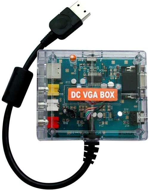

Image

It can be purchased at Racketboy or can be had for a few bucks cheaper on eBay.

I used this guide to help me figure out what exactly I needed to do, but it's really very straight-forward: if pin 6 and 7 are both grounded you will get 31KHz, if only pin 7 is grounded, you will get 15KHz. Dreamcast A/V pinout here. Since pins 6 and 7 only serve this purpose, to prevent 6 from being grounded, you can simply cut it. since we want to switch between 15 and 31KHz, we are going to add an on/off switch to complete or break the pin 6 connection.

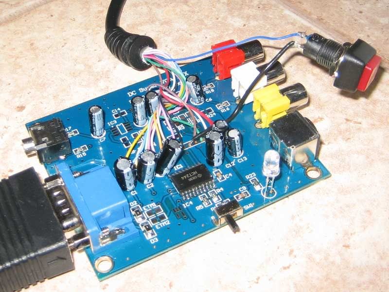
If you're using the same VGA box I used, this is nice and easy. Pin 6 should be the dark blue wire. Pull the hot glue off of the PCB where the wires meet the board being careful not to damage anything. Use your desolder braid and soldering iron on the back of the board to remove the solder from the dark blue wire's connection and pull it out of the hole. Now you need to use a multimeter to verify that this is pin 6. Use an alligator clip to connect one end to the dark blue wire, and use the other end to touch pin 6 on the part of the cable that makes contact with the Dreamcast's A/V out (remember that because this mirrors the A/V pinout, you're counting up from RIGHT to LEFT). If it turns out that your wire coloring is different, you might have to solder this back in and try a different one. You can do your best to deduce which one might be pin 6, but because pin 6 is grounded as long as it is soldered into the board, you won't know for sure until you desolder and remove the wire.

Once you have identified the correct wire as pin 6 and removed it from the board, connect it to one of the connections on your on/off switch. Now you'll need another stranded wire, ideally smaller than 22 gauge, but this is what I used by clipping a few of strands off so that it would fit into the hole on the PCB which we removed the pin 6 wire from. You need to solder one end of this wire into the pin 6 hole and the other end onto the other connection of on/off switch.

You should now have something that looks as below:

Image

When the button is on, pin 6 is grounded and you'll have a 31KHz signal, and when the button is off, pin 6 is not grounded and you will get a 15KHz signal. To test this out, set it to 15KHz and see if you can boot up Bangai-O. Bangai-O will not be able to boot in 31KHz, so if it it does successfully boot, your 15KHz setting is working. Now boot a Naomi game in 31KHz and make sure you have a beautiful, crisp 480p image to ensure your 31KHz setting is working.

Assuming there are no problems, you can drill a hole in the plastic enclosure. There is plenty of room right next to the TV/PC switch on the VGA box, and the blue wire should be able to just reach this far. Hold the two parts of the enclosure together without the PCB inside and drill a hole just to the left of the switch. The hole should be about half on the bottom side of the enclosure, and half on the top. Now simply reassemble the VGA box with the on/off switch fitting snugly in the hole you just made.
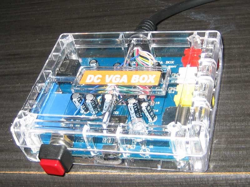

Image

If you have a different VGA box you're trying to do this too, things can get more complicated. I originally had a different VGA box that I accidentally destroyed while trying to mod. It turned out that pin 6 was connected to pin 7 way up near the pin header, so there was no pin 6 wire in the VGA box to cut. So other VGA boxes might not be so simple to work with, but the general idea is the same: install an on/off switch that completes/breaks the connection between pin 6 and the ground (or any grounded wire, including pin 7).

Enjoy Bangai-O in 240p!
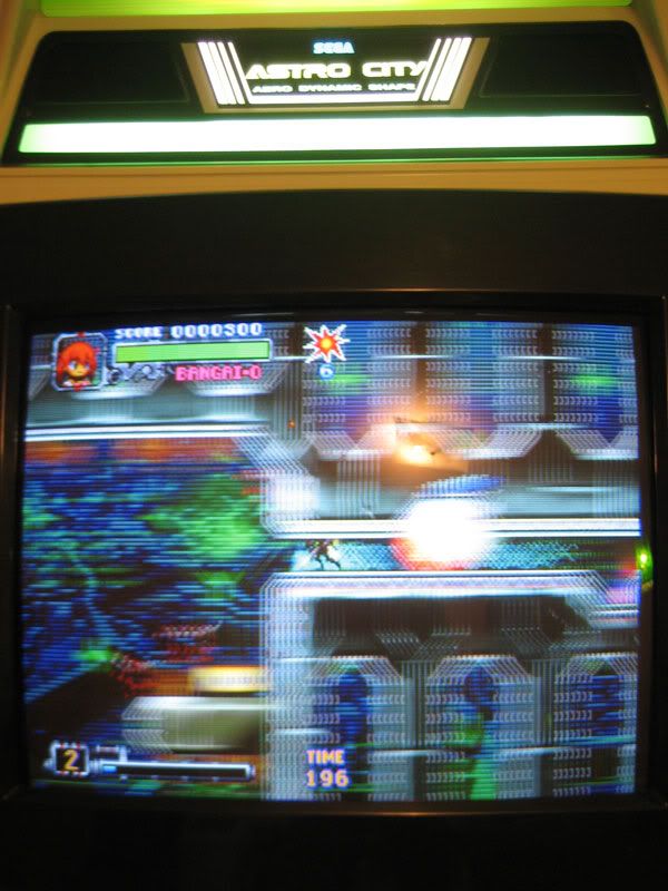


Image

Edit: To get this signal to display on most low-res monitors, you're going to have to toy with the sync signals to get a negative composite sync. I'm currently working on that now and will update this post with the details once I've got it working.

Important Note:
If you're doing this mod, there's a good chance you're looking to play SFIII Third Strike in 240p, but the American and Japanese versions have some sort of video protection that won't allow the game to run in RGB mode on a PAL console. You will simply boot into a black screen without applying this patch to the disc image:
1) look for
09 00 09 00 09 00 09 00 09 00 30 88 07 89 06 A0 09
replace it with
07 89 32 88 07 89 33 88 07 89 30 88 07 89 06 A0 09

2) look for
00 E0 00 E0 04 7F 26 4F 0B 00
replace it with
02 E0 00 E0 04 7F 26 4F 0B 00

3) look for
30 E0 02 2E 00 E0 26 4F 0B 00 F6 6E
replace it with
4C 84 02 2E 00 E0 26 4F 0B 00 F6 6E

4) look for
07 D3 31 60 19 40 03 C9 02 88 00 8B 03 E0 0B 00 09 00
replace it with
22 4F 06 B0 09 00 26 4F 03 E4 19 40 09 24 0B 00 43 60
« Last Edit: October 14, 2011, 04:22:28 am by hijakt »

hijakt

  • Trade Count: (0)
  • Full Member
  • ***
  • Offline Offline
  • Posts: 11
  • Last login:January 23, 2012, 05:19:10 am
Re: Dreamcast to arcade monitor: Complete (update)
« Reply #49 on: November 09, 2011, 05:31:55 am »
How did you guys connect the VGA cable that comes out of the box to the Arcade monitor? Will I have to get a VGA cable and cut that, then wire it directly to the wires from the Arcade Monitor. The monitor has a plug which has  Red, Green, Blue, a white and a black wire. I guess I should get a VGA breakout board, is that the best way?Where do I put the wires to the VGA connector? So it'll be breakout board to monitor, Dreamcast VGA box with pin 6 cut to breakout board. How would I know if I need a signal booster? Thanks for the help.
« Last Edit: November 09, 2011, 08:13:07 am by hijakt »

hijakt

  • Trade Count: (0)
  • Full Member
  • ***
  • Offline Offline
  • Posts: 11
  • Last login:January 23, 2012, 05:19:10 am
Re: Dreamcast to arcade monitor: Complete (update)
« Reply #50 on: November 10, 2011, 04:56:15 am »
Ok so I have the Red, Green, Blue, White and Black wire.
They represent
Red, Green , Blue, Composite Sync, Ground
So I solder them to
Red-pin1
Green-pin 2
Blue-pin 3
White/Composite sync-pin 13
Ground-pin 10

Can anyone confirm this.
PLEASE SOMEONE HELP !!!!!!!!!!

hijakt

  • Trade Count: (0)
  • Full Member
  • ***
  • Offline Offline
  • Posts: 11
  • Last login:January 23, 2012, 05:19:10 am
Re: Dreamcast to arcade monitor: Complete (update)
« Reply #51 on: December 12, 2011, 06:35:21 am »
Well I got it going and it looks great.One thing though, I have super Street Fighetr for the Dreamcast (A copy) and it rolls, where as my other games dont (CVS2 Shenmue.So I was wondering if its an issue with this title or its just a bad copy.Its a Revive DC version, perhaps something was changed? Ive read that Street Fighetr 3 On the DC has some sort of RGB  protection, does anyone know about this for Super.
The way I wired it is
Red-1
Green-2
Blue-3
Ground 5,6,7,8,9,10-
Sync 13, 14-

Works great.I hacked the VGA box easily.Just want to point out for anyone new to doing this, it's PIN 6 that needs cutting NOT wire 6.On the transparent VGA box, it works out to be wire 10 (The wires a labelled when you open it up 1, 15 on either end, ) It was a dark blue wire, exactly as the one pictured in the tutorial on Arcade Otaku.Please check yourself though, because there may be revisions etc, which are wired differently.

Frosty

  • Trade Count: (0)
  • Full Member
  • ***
  • Offline Offline
  • Posts: 337
  • Last login:December 30, 2021, 11:11:38 pm
Re: Dreamcast to arcade monitor: Complete (update)
« Reply #52 on: December 13, 2011, 01:31:12 pm »
Hey hijakt - glad you got it working!