Main Restorations Software Audio/Jukebox/MP3 Everything Else Buy/Sell/Trade
Project Announcements Monitor/Video GroovyMAME Merit/JVL Touchscreen Meet Up Retail Vendors
Driving & Racing Woodworking Software Support Forums Consoles Project Arcade Reviews
Automated Projects Artwork Frontend Support Forums Pinball Forum Discussion Old Boards
Raspberry Pi & Dev Board controls.dat Linux Miscellaneous Arcade Wiki Discussion Old Archives
Lightguns Arcade1Up Try the site in https mode Site News

Unread posts | New Replies | Recent posts | Rules | Chatroom | Wiki | File Repository | RSS | Submit news


Author Topic: Need help: Dreamcast pad hacking  (Read 10785 times)

0 Members and 1 Guest are viewing this topic.

ViciousXUSMC

  • Trade Count: (0)
  • Full Member
  • ***
  • Offline Offline
  • Posts: 213
  • Last login:July 28, 2009, 10:25:53 am
Need help: Dreamcast pad hacking
« on: February 25, 2009, 09:14:54 am »
I have a problem guys, I just got the urge to start my dreamcast pad hacks today (official sega ones) and the diagram from the shoryuken forums in there pad hack thread is more than sufficient to show the solder points.  I used my dremel with a wire wheel to expose them and have nice clean contact points.

The problem I am having is that the solder refuses to stick to the pcb completely, I will have it melted to the board totally flush and with zero force the solder and wire will come off, so little force that I cant even keep it on there enough to glue the wires down with hot glue after the fact.

Any hints for a solder newbie?  I am using radio shack clear flux solder and a radio shack soldering iron.  I tinned the wire first but even a glob of solder wont stick to the pcb.

ChadTower

  • Chief Kicker - Nobody's perfect, including me. Fantastic body.
  • Trade Count: (+12)
  • Full Member
  • ***
  • Offline Offline
  • Posts: 38211
  • Last login:October 19, 2022, 12:01:54 pm
Re: Need help: Dreamcast pad hacking
« Reply #1 on: February 25, 2009, 09:33:34 am »

Stop using the solder as a mechanical connection.  Tape the wire down just short of where you intend to solder it and let the tape hold it in place until the solder hardens.  Never expect the solder, even after hardening, to secure anything in place.  All the solder is is a permanent electrical connection.  Your wire should be small tug secure before you even try to solder it.

HaRuMaN

  • Supreme Solder King
  • Global Moderator
  • Trade Count: (+45)
  • Full Member
  • *****
  • Offline Offline
  • Posts: 10324
  • Last login:Yesterday at 03:35:02 pm
  • boom
    • Arcade Madness
Re: Need help: Dreamcast pad hacking
« Reply #2 on: February 25, 2009, 09:36:42 am »
If you do it correctly, the solder will be a mechanical connection.  I can pick up a dreamcast hack by a single wire and jiggle it with no ill effects, even before placing hot glue to firmly secure the wire.

Take a q-tip and rubbing alcohol, and clean the contact surfaces.

Also, apply some solder directly to the PCB contact points first. That way, when you attach your pre-tinned wire, you are basically attaching solder to solder, which will be pretty easy.

ChadTower

  • Chief Kicker - Nobody's perfect, including me. Fantastic body.
  • Trade Count: (+12)
  • Full Member
  • ***
  • Offline Offline
  • Posts: 38211
  • Last login:October 19, 2022, 12:01:54 pm
Re: Need help: Dreamcast pad hacking
« Reply #3 on: February 25, 2009, 09:51:55 am »
If you do it correctly, the solder will be a mechanical connection.  I can pick up a dreamcast hack by a single wire and jiggle it with no ill effects, even before placing hot glue to firmly secure the wire.

Sure, it can be, but it shouldn't be.  That's just not design for the long term.  It is also the exact reason his wire is pulling loose before the solder hardens - he has tension still on it and molten solder is not going to hold it in place long enough to harden.

And sure, you can pick it up by the wire that way, but how many times?  Is it really worth the risk of yanking that pad loose from the PCB?  You're putting hot glue on there afterwards for a reason. 


HaRuMaN

  • Supreme Solder King
  • Global Moderator
  • Trade Count: (+45)
  • Full Member
  • *****
  • Offline Offline
  • Posts: 10324
  • Last login:Yesterday at 03:35:02 pm
  • boom
    • Arcade Madness
Re: Need help: Dreamcast pad hacking
« Reply #4 on: February 25, 2009, 10:31:54 am »
I'm just saying that if you solder properly, the mechanical connection will be there, even though you don't want to use it as such.  The solidness of the mechanical connection implies a good electrical connection.

ViciousXUSMC

  • Trade Count: (0)
  • Full Member
  • ***
  • Offline Offline
  • Posts: 213
  • Last login:July 28, 2009, 10:25:53 am
Re: Need help: Dreamcast pad hacking
« Reply #5 on: February 25, 2009, 10:46:31 am »
30 min later pad #1 is done!

Its not the most pro job in the world but I did it some how, I clean off the tip of the iron some, tried to get a bit more solder on the wire when tining it, and then tried to get a small spec of solder on the pcb first by heating the pcb and then just quickly adding the wire into that. It worked well for most of the buttons and directions on the dpad, the ground was by far the hardest one to get to stick. After I had all the wires on there I glued them down well with hot glue I wanted to test them all with my mutli meter first before gluing them down but I eyed it down and it looked good so I did it before I broke one off by moving the wire around.

I just plugged it in to my dreamcast and tested every key by connecting a button wire to the ground wire and they all worked perfectly. Now I just need to wire it into a terminal block and find a project box for it and then wire those blocks into my db25 connector and of course do one more controller.

If it works it works!

This project that I am now going to dub M.A.D. (multi arcade desk) is showing more signs of being worth it than it did a week or so ago when I thought I had made a bad choice making it modular and not just sticking with PC and emulated dreamcast because I decided I want to add my wii to the mix also mostly due to the fact that I plan to get TvC (tatsunoko vs capcom) and I think that arcade controls will be vastly better than a classic controller for that.

Just how hard is a Wii classic controller HarumaN?  I could optionally do a gamecube controller instead.

Still even though I got one done I would like any tips if you have them, oh and I used a clamp I bought to hold the pbc in place before I had it unsecured so that helped too.
« Last Edit: February 25, 2009, 10:51:36 am by ViciousXUSMC »

HaRuMaN

  • Supreme Solder King
  • Global Moderator
  • Trade Count: (+45)
  • Full Member
  • *****
  • Offline Offline
  • Posts: 10324
  • Last login:Yesterday at 03:35:02 pm
  • boom
    • Arcade Madness
Re: Need help: Dreamcast pad hacking
« Reply #6 on: February 25, 2009, 11:01:47 am »
Definately use a clamp, hold the wire in one hand, soldering iron in your other (dominant hand).  Using a lighted magnifying glass can help, too.  Also, I cut the length of wire needed before soldering, to prevent undue strain as the joint hardens.

I have not done a Wii classic controller yet.  I would assume it should be fairly straightforward to do.  I do know that the GameCube pad (official) is hackable.

ChadTower

  • Chief Kicker - Nobody's perfect, including me. Fantastic body.
  • Trade Count: (+12)
  • Full Member
  • ***
  • Offline Offline
  • Posts: 38211
  • Last login:October 19, 2022, 12:01:54 pm
Re: Need help: Dreamcast pad hacking
« Reply #7 on: February 25, 2009, 11:04:45 am »
I'm just saying that if you solder properly, the mechanical connection will be there, even though you don't want to use it as such.  The solidness of the mechanical connection implies a good electrical connection.

It shouldn't, though.  Strain relief is important.  You shouldn't be able to tug on the electrical connection without first failing the strain relief.  I get that this is a grey area here but the best advice we can give a newbie is good general practice.

ViciousXUSMC

  • Trade Count: (0)
  • Full Member
  • ***
  • Offline Offline
  • Posts: 213
  • Last login:July 28, 2009, 10:25:53 am
Re: Need help: Dreamcast pad hacking
« Reply #8 on: February 25, 2009, 11:11:36 am »
I just got done prepping the 2nd pad, I think I just noticed maybe what the big problem was.  Using a high speed dremel to remove the material it looks like it was leaving behind a residue of sorts from all the micro sized particles of the pcb being scraped away.  I bet it was those particles that were keeping me from being able to stick.  This pcb I am going to clean with a q-tip and rubbing alcohol first before I start to solder.

HaRuMaN

  • Supreme Solder King
  • Global Moderator
  • Trade Count: (+45)
  • Full Member
  • *****
  • Offline Offline
  • Posts: 10324
  • Last login:Yesterday at 03:35:02 pm
  • boom
    • Arcade Madness
Re: Need help: Dreamcast pad hacking
« Reply #9 on: February 25, 2009, 11:16:38 am »
I'm just saying that if you solder properly, the mechanical connection will be there, even though you don't want to use it as such.  The solidness of the mechanical connection implies a good electrical connection.

It shouldn't, though.  Strain relief is important.  You shouldn't be able to tug on the electrical connection without first failing the strain relief.  I get that this is a grey area here but the best advice we can give a newbie is good general practice.

Oh, I still use hot glue, no matter how solid the connection.  As many pads as I sell, I can't afford to have wires coming off and lifting traces, etc, even once its left my hands.  You'ld have to pop the hot glue off to put any strain on the solder joint.


HaRuMaN

  • Supreme Solder King
  • Global Moderator
  • Trade Count: (+45)
  • Full Member
  • *****
  • Offline Offline
  • Posts: 10324
  • Last login:Yesterday at 03:35:02 pm
  • boom
    • Arcade Madness
Re: Need help: Dreamcast pad hacking
« Reply #10 on: February 25, 2009, 11:17:25 am »
I just got done prepping the 2nd pad, I think I just noticed maybe what the big problem was.  Using a high speed dremel to remove the material it looks like it was leaving behind a residue of sorts from all the micro sized particles of the pcb being scraped away.  I bet it was those particles that were keeping me from being able to stick.  This pcb I am going to clean with a q-tip and rubbing alcohol first before I start to solder.

Yep, exactly why I clean after using the dremel.

ViciousXUSMC

  • Trade Count: (0)
  • Full Member
  • ***
  • Offline Offline
  • Posts: 213
  • Last login:July 28, 2009, 10:25:53 am
Re: Need help: Dreamcast pad hacking
« Reply #11 on: February 25, 2009, 12:16:59 pm »
Well the guess was probably correct my cue tip came off solid black full of debris.  The 2nd controller came out so much nicer, there is just enough solder on the joint to hold it, no globs at all except for the right should button.  I hot glued as I went so it was more neat and no burned wires lol by accidentally touching a wire while working on another join.

In all the perfection that is the 2nd pad, I made one mistake, I forgot to solder the left shoulder button.  I already put my stuff away so I will let it be, I have to solder the wires to those DB25 connectors so I will do it then.  I tested it and it works perfectly.  Though I have a problem.  I have to wiggle the controller port around for it to work so I think my jack is about gone, I also have to wiggle the vga adapter connection around to get a good color screen.  My dreamcast is showing its age and since I am going though so much trouble to use it I may want to replace it with another one.

adding a drop of solder to the pcb first seems to be the key to make it stick, I guess letting it run down the wire was making it so that the pcb trace was not hot enough, also doing it this way let me use less solder.

It was not hard at all after I got the hang of it, but this is very amateur soldering with big traces to work with.  Something like what I tried about 3 years ago, replacing the opamp on my x-fi card is impossible at my skill level (and tools too)

I got some pictures of both pads that I will post up later tonight, and I may run out to radio shack when my wife gets home to see if they have the stuff I need to complete the project.

Oh HarumaN, I only need the VMU dock on one pcb really, this is going to be a dual controller in 1 box thing, can I unscrew and remove the dock from P2 controller without making the controller none functional easy you think?

ViciousXUSMC

  • Trade Count: (0)
  • Full Member
  • ***
  • Offline Offline
  • Posts: 213
  • Last login:July 28, 2009, 10:25:53 am
Re: Need help: Dreamcast pad hacking
« Reply #12 on: March 02, 2009, 04:09:28 pm »
I think the semi final product could make even HarumaN proud :P

Pics:

Pad 1 Done


Pad 2 Done


My Pin Out for both Pads


Both side by side, the cut VMU holders so they will mount flush in a project box, and the DB25 connectors that will be wired to them for interfacing


I say semi final as they still have a home to go to inside a big project box but the pads themselves are ready to go and both tested fully functional.

I had one hickup, a button on the red pad when I tested it out has 0 resistance, The glue did not stick on the pad and the wire moved when I made a sharp tug/bend.  Not sure how it got grounded as there should be no ground near it but I had to melt the glue with a hair dryer remove the wire and glue and re solder it.  Its testing where it should be now like 10.1 ohms (on the 200k setting) I am proud of my work ^^ and cant wait to get this going to the final phases.

Looks like I may be doing this with PSX pads too so I can use them with a gamecube adapter and play my Wii games on the arcade controls.  I was told its best to hack a psx pad and use an adapter than to mess with gamecube or wii classic controllers.

HaRuMaN

  • Supreme Solder King
  • Global Moderator
  • Trade Count: (+45)
  • Full Member
  • *****
  • Offline Offline
  • Posts: 10324
  • Last login:Yesterday at 03:35:02 pm
  • boom
    • Arcade Madness
Re: Need help: Dreamcast pad hacking
« Reply #13 on: March 02, 2009, 04:11:43 pm »
I think the semi final product could make even HarumaN proud :P

Hey!  Nice work, there!  :cheers:

HaRuMaN

  • Supreme Solder King
  • Global Moderator
  • Trade Count: (+45)
  • Full Member
  • *****
  • Offline Offline
  • Posts: 10324
  • Last login:Yesterday at 03:35:02 pm
  • boom
    • Arcade Madness
Re: Need help: Dreamcast pad hacking
« Reply #14 on: March 02, 2009, 04:13:39 pm »
Looks like I may be doing this with PSX pads too so I can use them with a gamecube adapter and play my Wii games on the arcade controls.  I was told its best to hack a psx pad and use an adapter than to mess with gamecube or wii classic controllers.

If you are going to do that, I would recommend the Nubytech Street Fighter controllers, they are SUPER easy to hack, already bare so you can solder right to the pads as they are.

ViciousXUSMC

  • Trade Count: (0)
  • Full Member
  • ***
  • Offline Offline
  • Posts: 213
  • Last login:July 28, 2009, 10:25:53 am
Re: Need help: Dreamcast pad hacking
« Reply #15 on: March 02, 2009, 04:47:59 pm »
Looks like I may be doing this with PSX pads too so I can use them with a gamecube adapter and play my Wii games on the arcade controls.  I was told its best to hack a psx pad and use an adapter than to mess with gamecube or wii classic controllers.

If you are going to do that, I would recommend the Nubytech Street Fighter controllers, they are SUPER easy to hack, already bare so you can solder right to the pads as they are.

None on ebay, some on froogle from a place called arcadeshock for $20 but they have no ratings, plus they say PS2 pads.  I was under the impression from what I was told to just use PS1 pads.  They look super super easy to hack too.

I'll have to do the research for the adapter & controller when the time comes I guess.  I want it mostly so I can play Tatsunoko vs Capcom on my Wii with authentic arcade controls.

ViciousXUSMC

  • Trade Count: (0)
  • Full Member
  • ***
  • Offline Offline
  • Posts: 213
  • Last login:July 28, 2009, 10:25:53 am
Re: Need help: Dreamcast pad hacking
« Reply #16 on: March 07, 2009, 09:23:45 pm »
Posting back to show what became of those hacked pads.  It took all day.  Much more work and tools needed than I thought but it came together somehow, and just like the IPAC project box adapter I was lucky enough that everything worked first go perfectly. 

First was the fact I could not find a project box the size I needed for 2 pads and they were expensive for big ones so I though I could save $$$ to do it myself, after the tools... probably not but I have the tools for the next box (the Wii adapter) so that one should be cheaper.

I decided a material that was easier for me to work with and would be cooler than wood was plexiglass.

I asked what was the best way to cut the stuff on the cheap and I was told a scoring tool.  It worked but I messed up some some of my lines drifted due to my clamps moving or because the cutter moved.  So my box was not 100% even, and I put it together with hot glue so its hard work to get it perfect when assembling, though my metal square helped a lot.

After over an hour cutting and sanding down the pieces I got the main box together with no lid and gave the pads a test fit:


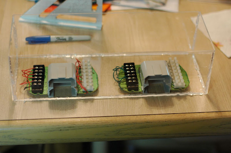
I know it looks bad, I have no idea how to get hot glue to be "neat"


Then I used 4 drill bits going from small to larger to make holes approximately where I would have the DB25 connector, the 2 controller cables, and the VMU slots, then I opened my router and used it for the first time!  It was fun and wow what a great tool (that $25 laminate trimmer from harbor freight w/ the 3 bit set from them also) this "mini router" was perfect for a job like this as I had to hold the weight of the router up to not bend the plexi.  It seemed to not want to move if I let it go slow it would melt the plexi and get stuck and also make a build up on the side so I have to move fast.  I got distracted when the DB25 connector fell and moved the router and chipped it on one spot.  But I tested the VMU, DB25 Connector, & controller cables and it all fit ok.  The DB25 fit was a bit too loose to use the screw holes correctly though.

I bought sand paper & a file to make this part perfect but the router did a better job and I was to impatient to make it perfect.

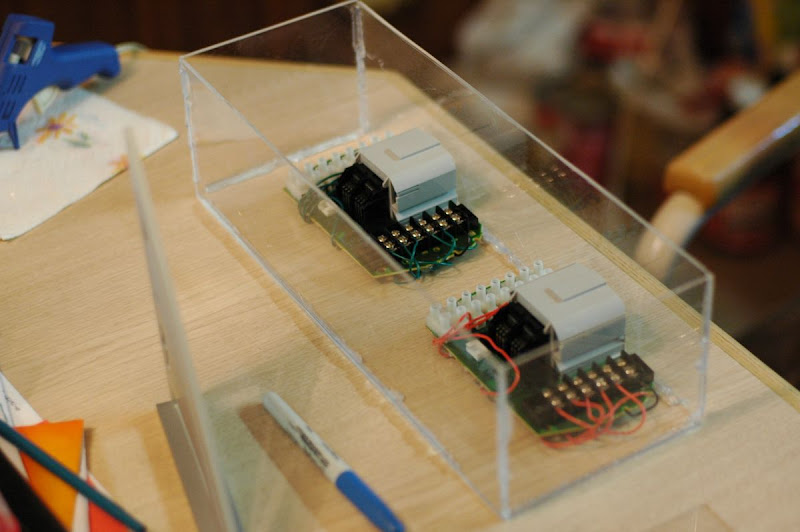
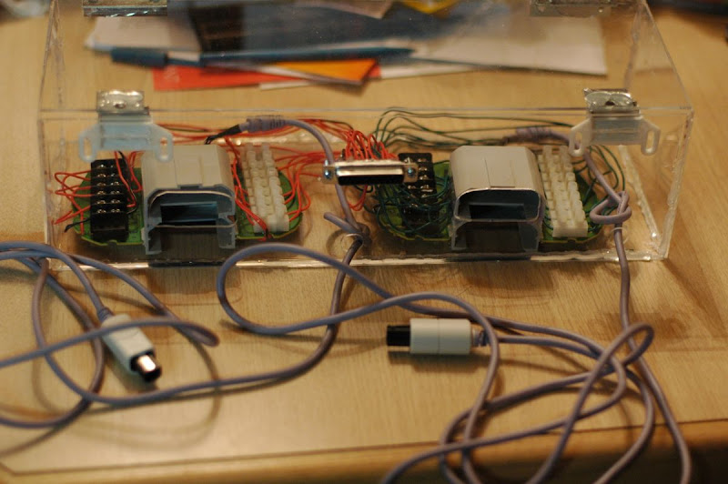
Here is how it looks half way:


I used hinges & magnets made for cabinets.  Worked to my advantage as the lid would have fallen inside the box but the magnets hold it up.  I did not take into account that there IS a thickness to the plexi so when making a box you need to offset for that...


I forgot to take pictures of the part where I soldered the DB25 connector and the wires, it was easier this time after doing it for the IPAC, I learned having it mounted was important so I took an old dirty 2x4 from outside and screwed the DB25 header onto a board to work with it.  I only had one wire out of the bunch that I had to resolder.  Also my pin out makes it easy for me to just solder away.

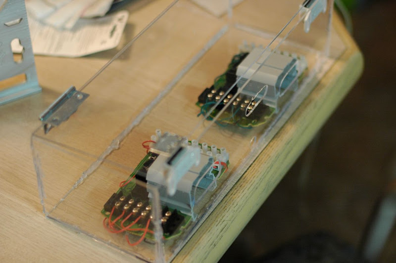
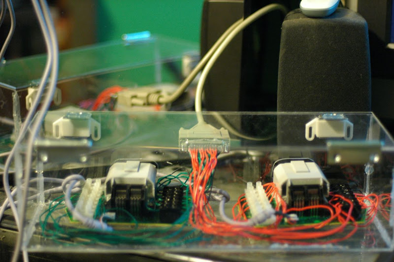
So this is after I did all that, put the wires in the box, cut them closer to length and attached them.


For the red P1 wires on top I could eye them to see where I needed to connect it, but for the green I was blind so I had to play roulette with my multimeter while keeping track of what pin I was wiring to know what wire to attach where.  My wire job did not come out as neat as I wanted but its far better than just a mess.


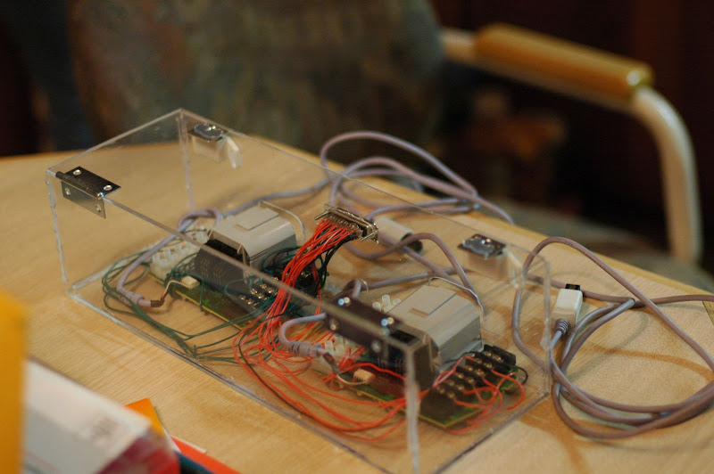
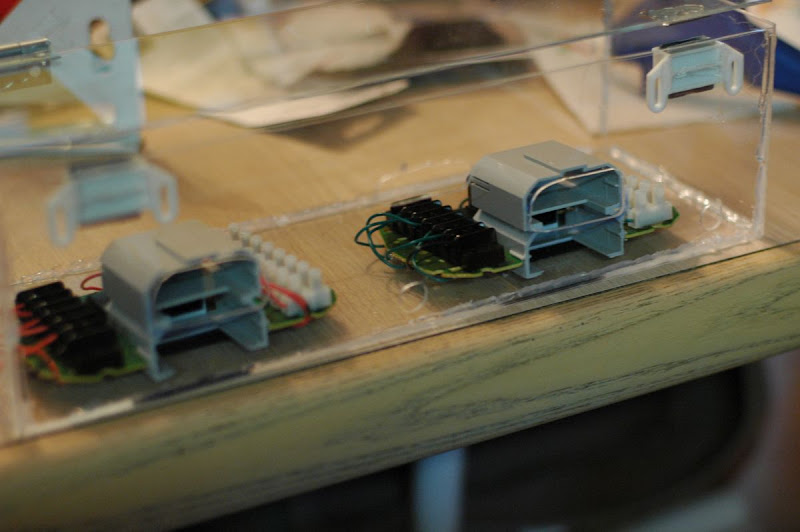
And here it is actually hooked up and in action.


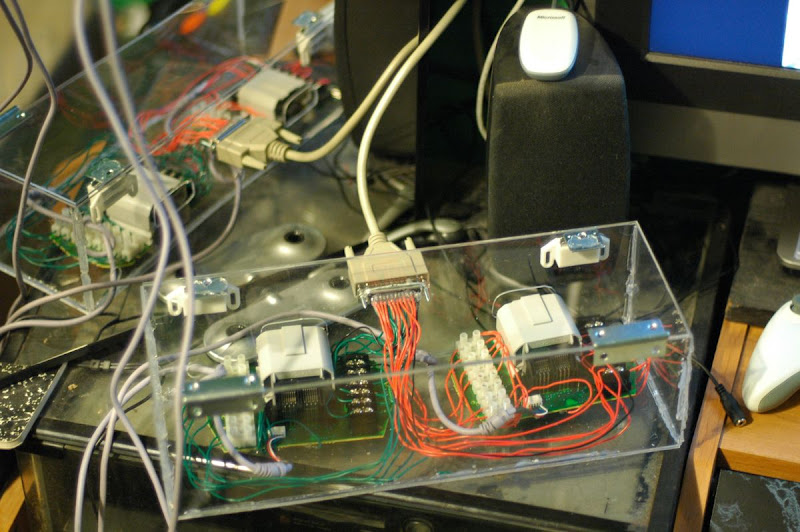
I made the box big after having a very hard time with the small IPAC box, but then looks like I made this one too big.  I am happy with the width & depth, but it was too high.  If it had been just as tall as needed it could have set on my desk, but due to its size it has to sit beside the dreamcast ontop of my dresser.

But hell it works, and maybe I will use that space for something :P

Now all that is left is to photoshop the pinout and print a dreamcast logo to stick on there.

Then next project is the Wii adapters! Since they are smaller and its the 2nd time round I expect it to be easier.