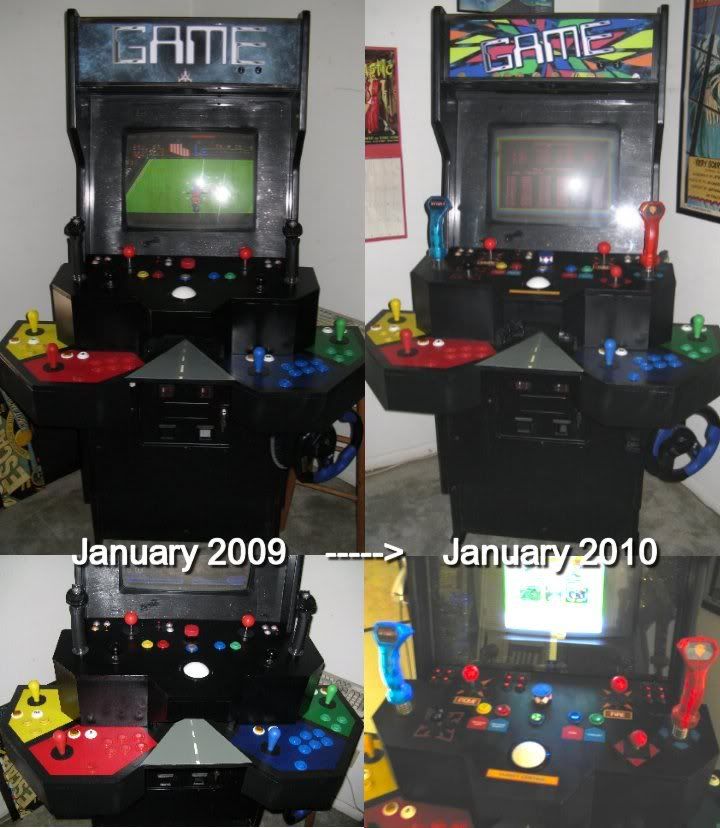
(above pic shows progression since this first post, updated as of 1-16-10.)
Here she is in her first fully playable version, with her original header (I have a new header, pictured below, although that one's about to get replaced too).
Before I even get going here, I need to throw out a wave of thanks to all you guys who have given me advice here, Andy at Ultimarc (who went above and beyond), the folks at Mike's Arcade, and those poor suffering souls at
Electronic Parts Outlet (if you're working on a project anywhere near SW Houston, definitely check out EPO). Also, credit must go to Jeff Allen and his
Supercade for inspiring me with his two-tier design.
She started out life as a
Phoenix (at least that's what the nameplate on the back says). When I got her at an auction in Mesquite back in '96, she was a JAMMA cab with
Escape From the Planet of the Robot Monsters complete with two Hall Effect joysticks. Worked great and an absolute steal for $85. I got a few envious looks and comments as I wheeled her out. The burn-in on the monitor (not too bad, but it's there) shows that it once ran as a
Rampage as well.
I sold the Hall Effects and the metal control panel on Ebay for $130, and the
Robot Monsters boards for $100. I now had my wife-proof funds to begin amassing controls.
The PC dropped into my lap; a 1.8 gHz AMD Athlon, and I put in a gig of RAM, Windows 2000, MAME32 v112, Daphne, Visual Pinball, ZSNES and other console emulators. It runs everything great up until polygons start getting involved in the 1990's. At some point I plan to replace this rig, but for now it does everything I want it to do just fine (Space invaders to Street Fighter). I already had an ArcadeVGA I had bought a couple of years ago when I
meant to get started on this, but I didn't actually begin real work on the project until August of '08, and finished (apart from a few little to-do's) just before Christmas '08.
The top tier is the "Classics" tier. Everything is wired through an I-Pac 4 except the trackball, spinner and analog sticks:
2 8-way leaf switch joysticks (Mike's Arcade) for Robotron, etc. ...mainly Robotron. Constantly Robotron.
2 4-way microswitch joysticks (also Mike's), the left one is set diagonally for Q-bert, the right one normal for Pac-Man, Donkey Kong, etc.
2 analog trigger joysticks (Saitek Cyborgs, Ebayed for 8 bucks each). I plan on replacing the grips with Randy's awesome Tron and Satan's Hollow grips (actually, I was just waiting for the Satan's Hollow ones to happen, and when I checked the forum today I was surprised to see I had missed their debut).
1 U-Trak trackball (Ultimarc, wired to their Opti-Pac)
1 homebrew spinner (detailed below)
5 arcade buttons (Asteroids array, color coded for Mouse Trap!)
12 homebrew "Atari Volcano" buttons (buttons from EPO, "Volcanoes" crafted out of Super Sculpey). ESC, Enter, MAME settings, etc.
2 pinball flipper buttons (on sides of top tier, visible in pics toward the bottom).
The bottom tier is set up for MK/Street Fighter and 4 player games. 60 bucks bought all the lower panel controls (and the top tier buttons) in a single purchase on Ebay.
Player 1 - 1 red Happ competition joystick, 6 convex buttons, 1 concave button, 1 start button, 1 coin button.
Player 2 - 1 blue Happ competition joystick, 6 convex buttons, 1 concave button, 1 start button, 1 coin button.
Player 3 - 1 green Happ competition joystick, 3 concave buttons, 1 start button, 1 coin button.
Player 4 - 1 yellow Happ competition joystick, 3 concave buttons, 1 start button, 1 coin button.
Each joystick input on the I-Pac 4 is actually wired to two joysticks; one on the top tier, one on the bottom. You're either on one tier or the other, and it's a great way to add other types of joysticks without needing extra inputs (or I-Pac's). For example, the left red ball stick on the top tier is wired to the same inputs as the red player 1 stick on the bottom tier.
The Logitech Steering Wheel (made for Playstation 2 Gran Turismo 3) clamps into the center bay for play, and down below when not in use. The pedals can be stashed inside the coin door bay.
A better picture of the keyboard is below. It's been repainted, and labeled for Thayer's Quest..!
...No one but me has yet to be excited by that.
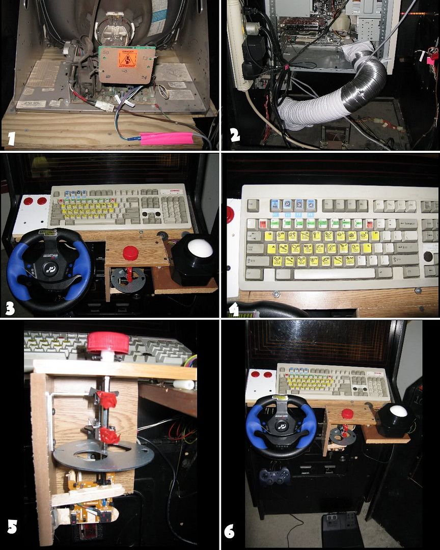
1. Wells-Gardner 19K7906 monitor, wired to ArcadeVGA. I can find almost nothing about this monitor. I'd kill for a manual. But I've managed to get it to do everything *except* adjust the horizontal size-- that coil doohicky feels stuck tight. Fortunately the H size was already set pretty well, I just wanted to tweak it a tiny bit.
2. Powerstrip feeding PC, monitor, speakers and steering wheel. I secured a clothes dryer duct hose to one of the vents on the cabinet floor, then a PC fan to the other end. The hard drive was running pretty hot until I started feeding it cool air from the floor, and I haven't had a problem since.
3. A true Frankenpanel. The U-Trak has arrived! The two red buttons in the UL are the mouse buttons. In the center is homebrew spinner v2. Serious lack of joysticks at this point.
4. Thayer's Quest stickers on keyboard.
5. Homebrew spinner v2; v1 had the same knob, but was way too flimsy. It was a Western Digital hard drive jobber that obviously wasn't going to last under any wear and tear (the shaft, mainly). But when I went to rebuild it, I had ruined what Western Digital platter hubs I had-- and what I ended up using were 2 of the
actuator arms from the butchered hard drives. They each have a small (1 1/2 cm diameter) spinning piece-- the actuator shaft-- with a screw on one side and a threaded hole on the other. They worked
great, AND I found shafts at EPO that would screw into them! Another plus with the actuator arms-- they don't need to be Western Digital (to get the pre-centered hole). Of the four HD's I dismantled for this project, only 2 were WD, but all the actuator arms had a screw on one side, and a threaded hole on the other.
The knob is a cap from a gallon jug of Lactaid milk-- perfect size, and nice ridges on the side. I filled the cap with hot glue and put a plastic cylindrical spacer in the center (you can see one of the spacers on its side, in the upper right of the pic, leveling out the top wood piece of the spinner). Two screws secure the knob to a hexagonal metal shaft from EPO. That shaft screws into the hard drive actuator arm, and another shaft links it to the second arm.
The actuator arms are the two pieces with red electrical tape on their ends-- because those ends are SHARP AS HELL and I had a million tiny cuts on my fingers before I even knew it.
The two actuator arms are clamped to two L-brackets, which are in turn screwed into the wood housing. Below the actuator arms are two more short hexagonal shafts, with the spinner weight screwed tight between them. The spinner weight is a metal facing from a circular electrical socket (another Home Depot "Ah-HA!" moment).
The shaft piece underneath the weight is a male end where it's secured to the weight, and female on the other. The mouse spoke wheel is screwed into that end.
The circuit board is from a cheap Gateway mouse, whose wheel was never detected by any computer other than the original Gateway, so I decided it had to die. But what made a crappy mouse made an awesome spinner. On the first spoke wheel I tried, following some guide I was reading (probably here), I cut out every other spoke to accomodate high speed spins; but that wheel wasn't detected well at all. On a whim, I tried the second, unmodified, wheel and it worked perfectly.
I have spun the daylights out of this thing, and I have never managed to spin it fast enough to get that jerky effect I have experienced all too-frequently on PC mice and trackballs. I have NO idea why the Gateway mouse parts worked so perfectly, but I get insanely fast motion onscreen and yet, still perfect precision. After adjustments for tension, leveling, etc., I now get 13 seconds of spin on this thing from a single good twirl. I'm working on a design for another version that will more solidly brace the actuator arms, and also reduce the depth-- it's pretty tall, about 8 inches, but the room was available in the final control panel, so the height was never really a problem.
6. Oh, yeah, the car pedals and the do-fer Logitech joystick down below.
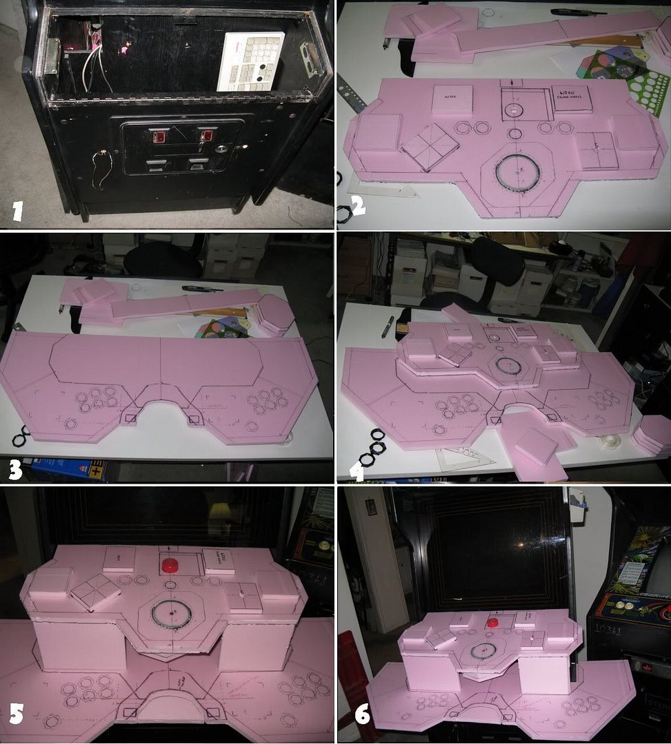
1. The empty control panel bay. Also, the coin mechanism has been removed to make the coin door into a storage bay for the pedals, and easy access to the 2 USB hubs (for Opti-Pac, analog sticks, steering wheel, and disco ball power. ...More on the disco ball later.

)
2. Beginning the design model. I bought an 8x4 sheet of 1/2" foam core insulation for $10 at Home Depot. The idea here was to build a full size, easy modifiable model so I would be sure that the controls as I had drawn them out would not be too crowded, or poorly positioned in general. MERE WORDS CANNOT DESCRIBE the imagined nightmare scenarios I avoided by building this model-- in fact, this pic shows that I incorrectly positioned the center line; it's an inch off. If I had realized that after cutting
wood, I'd'a cried like a baby.
The foam core is light as a feather. You can cut it with an exacto knife instead of a saw. You can attach it to the cabinet with scotch tape instead of screws. And if you screw up a cut, it's a simple matter to repair-- slice the right size/shape piece to fix it, and tape it on. And once you have the model completed, its pieces serve as crude stencils on the wood, making sure your measurements are always in the ballpark before you make an absent-minded cut.
The square pieces on the top are measured to represent the joystick footprints, so that I can move them around and make sure that the arrangement I want for my hands will fit together underneath the panel. The spinner, trackball and button footprints are drawn on, as they would not likely be moving from their centered positions.
3. The lower tier model. Center area stenciled from top tier model to indicate correct overhang. Note the curved divot in the center, inside the steering wheel footprint.
4. Looking at the two tiers stacked.
5. Adding the front 'legs' for the top tier. Once these pieces were finished, it would be time to start cutting wood. The remaining pieces would all be angled facing pieces, and would require much more precise measurements made off of the actual construct. Modeling those pieces at this point would be a waste of time. Also notice that the center divot from #3 & 4 has been replaced (yaaaaay exacto knife and scotch tape). It weakened the structure, and was unnecessary-- the top tier controls turned out to be easy and comfortable to reach.
6. "OMG this is actually going to happen. ...OMG I better make this thing easy to take apart, 'cause it won't fit through the door like that." (All-original Super Cobra cab makes Hitchcockian cameo just before acquiring White Elephant status.)
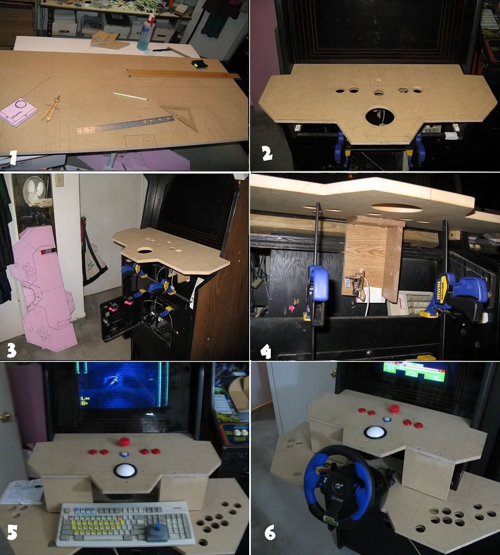
1. Drawing out the actual lower tier, stenciled from the model then measured for accuracy and symmetry. On the table is a 2'x4' piece of 5/8" MDF (Medium Density Fiberboard). If you're unfamiliar with this stuff, it's like Super-Cardboard. No splinters, smooth as silk and very sturdy. It makes a heck of a lot of very fine dust when you put a circular saw to it, though.
I actually did all the cutting out on the 4'x 12' porch of our usptairs apartment. It took a couple of weeks before my neighbors got up the nerve to finally ask me what the heck I was doing up there.
I got a great deal at Home Depot on a cordless circular saw and cordless drill combo; for $100 I got both tools, 2 batteries, charger and carry-all, AND I got to pick another tool from the line, so I got a little router/trimmer-- and all 3 share the same rechargeable batteries.
Then I bought an 8'x 4' sheet of MDF at Home Depot and had them cut it into 4 pieces-- none of the pieces I was planning to cut were larger than 2'x 4', and if all went well, I had twice as much as I needed (plus turning the extra wood into new shelves does wonders for justifying surprise power tool purchases with the wife).
2. The top tier cut and in place! You can put your hands on it and pretend there are buttons there! ...if you're into that sort of thing. Holes cut for trackball, spinner and button array. Holding off on joystick holes until analog joystick footprints are confirmed.
3. Setting angle for top tier.
4. Wondrous quick clamps! Making sure the bulky spinner housing fits.
5. You can actually play games on this thing! Bottom tier and top tier legs cut and in. (Note the small joystick that magnetically locks on to the arrow keys. Neat little thing I got for 3 bucks at Microcenter. Yanks completely off in an even moderately heated game of Pac-man, though.)
6. Getting real measurements for the steering wheel dock pieces.
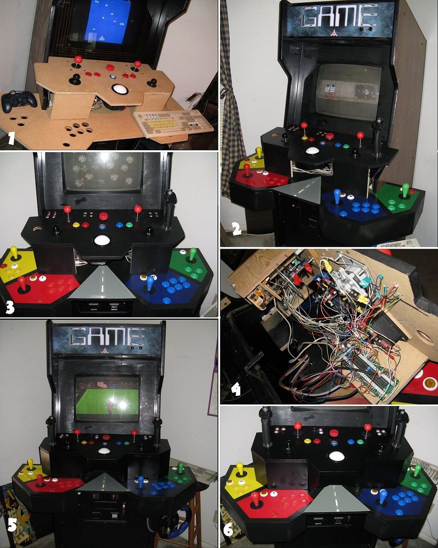
1. 8-way leafs and 4-way micros installed. Project nearly comes to complete halt as Robotron roars to life.
2. At this point I realized that if I finished the upper tier completely and painted it, I was going to be in for a lot of cramped-hand-time when I reinstalled all the controls. So I decided to paint the panels as finished so far, then reinstall the controls with all that nice open space on the sides. The remaining panels I would paint individually before securing them to the full control panel, then touch them up as needed. Also, the first Cyborg stick is in-- TRON TIME!
I painted both tiers with a semi-gloss black. The top tier got about 8 coats, then about 4 coats of clear polyethylene (tough stuff). On the bottom tier, I masked the black borders for the colored player areas, then I used a sponge to apply thick coats of the four colors. The result was a raised, rougher, bumpy texture in the red, blue, green and yellow areas, contrasted against the smoothness of the black borders. It was something I tried on a whim, and was really happy with how it came out. Then I added the 'road' to the steering wheel bay, and gave the whole thing the same 4 coats of polyethylene. Drink-spillable!
3. Another view. 1 joystick left to acquire!
4. Inside the top tier. Scary!
5. Ready for all gamers!
6. Another angle. I just like the depth suggested by the reflections in the top tier facing.
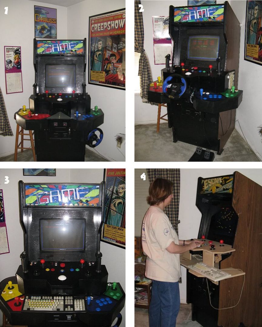
1. The new header is in, and the 80's corner is coming together (The
Creepshow poster was given to me long ago by a good friend whose grandmother was in the movie-- she was the maid in
Father's Day).
By now I've long since flipped the cheap cardboard bezel, painted it black, and given it a light sprinkle of silver glitter for a 'starfield' effect.
The header as seen here is pretty close to what will be the finished version (until I tire of looking at this design, anyway). There's a top layer of 'cosmic swirl' in this one that ended up looking like crap when backlit. The one I'm fixing to put in gets rid of that, and the colors look much bolder.
2. Steering wheel and pedals in place. Keyboard is hanging on pegs on the side of the cab. Look closely to the UL of the keyboard, and you can see the right flipper button (for Visual Pinball).
3. Keyboard in place for file maintenance-- or THAYER'S QUEST!!! I added some rubber feet to the underside of the keyboard in strategic positions so it can sit in that spot, well supported at all four corners, while also not pressing any buttons on the lower tier.
4. My wonderful, beautiful, understanding wife getting her
Centipede on in early days. When I snapped this pic I started worrying less about getting killed in my sleep.
On the header you can see the Tone and Volume knobs. I used a 3" hole saw on the underside of the header and put in a couple of stripped Dell speakers (there's a center hole from the original mono speaker that I covered). The header is lit by a 100 watt flourescent bulb (one of those twisty ones that fit in a regular lamp socket). I made a whitebox inside the header to spread out the light.
...Then I made my DISCO BALL!
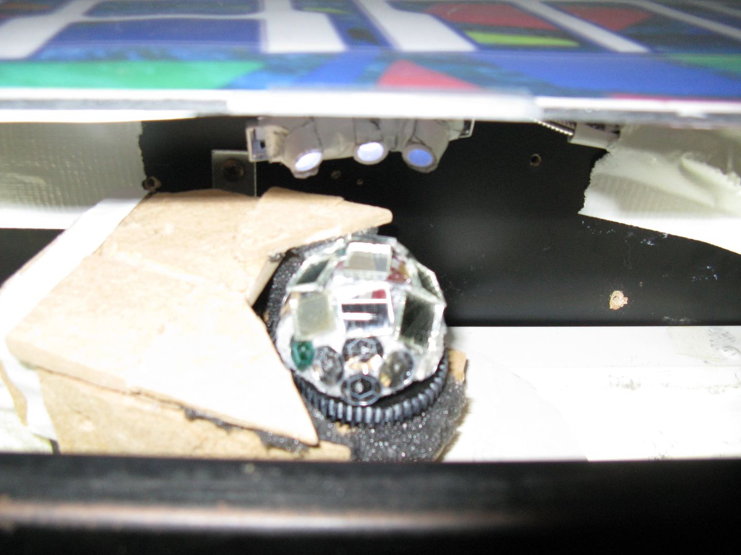
I went to Fry's and bought a little plastic dog that plugs into a USB slot, then it humps your laptop. I then eviscerated that randy animal, and extracted from him his tiny 5v motor with USB plug. The motor is about the size of a pencil eraser, and it spins a small screw-gear VERY fast. Then I got a packet of lightweight plastic gears at EPO, chained them small-to-large, small-to-large until I had the final rotation slowed down to about 10 RPM (by the time I had this doohicky working, it was 4am and I felt like a mad watchmaker). Hot-glued to that last gear is a 1/2 sphere of styrofoam, and I scavenged a few mirror bits (from an old disco ball that came as a package deal with my wife) and glued them to the styrofoam. BAM! USB powered micro disco ball.
The light is 3 LEDs on a bendy metal arm with a USB plug. I cut a white Bic pen into 3 small tubes and put them on the lights-- because as a wise man once told me, "the tube MAKES the disco ball". ...Well, he may not have been wise, but he could dance.
It doesn't read very well in these pics, but the colored squares on the header are coming out of a black hole-type thing. Inside the header, the light is blocked in the middle and reflected out to the sides. In the middle, the disco ball projects its whirling pattern of lights from the dark center of the black hole.
I believe I am now at the end of what must be the longest post I have ever made anywhere. I knew it would be epic, and I meant to tell my tale back in January, not long after I felt I had reached completion-- instead, Robotron is now at 384 plays. And I still have some to-do's; there are some open areas such as under the bottom tier, and a buddy of mine who works at a sign shop is going to cut some nice vinyl vector art for me.
But for now, GAME lives, and I have this post out of my system!


 Home
Home Help
Help Search
 Login
Login Register

 Send this topic
 Print
Print Topic: My sweet baby... GAME (top tier rebuild) (Read 23196 times)


