One of the members here asked me about my trackball LED control.
http://forum.arcadecontrols.com/index.php?topic=82241.msg897333#msg897333 I thought that I would share the answers with the general population.
First, I'd like to say...
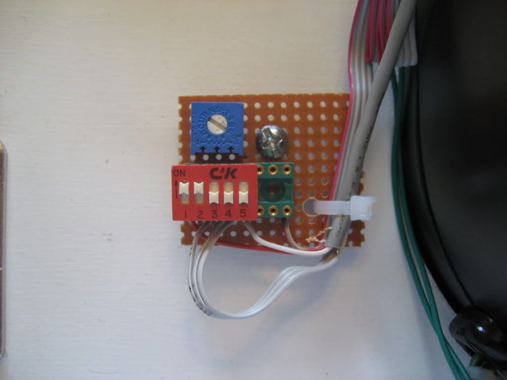
LED's require a current limiting resistor to be in series with the power supply. This limits the current once the LED lights up. The LED lighting module on the Electric Ice Trackball already has these resistors in place... so lighting one of the LED's on that module is simply a matter of supplying 5v and Ground to the appropriate LED.
The USB interface on the trackball gets 5v from the computer so it's a perfect place to get the power that's needed to light the LED's.
The LED control that I built does nothing more that that.... it supplies 5v to each of the 3 LEDs.
The tweaks...
I added a switch so I can control [on/off] for each individual LED... and... I added a variable resistor so I could supply less than 5v allowing me to dim the LED.
... side note... looking back... I probably could have skipped the dimming... I've never dimmed the trackball... it looks really good at full brightness.
> How hard was it to build?

That depends. If you can't solder, you're going to have a tough time. It wasn't difficult to build... you do have to have some dexterity to wrap small wires around small pins.
> Are the parts pretty easy to get at a Radio Shack or Fry's?

I had the parts in my parts bin. Yes, Frys would probably have these parts... Radio Shack; I'm not so sure.... they aren't what they use to be. You can definitely get them from DigiKey.
> What was the cost?
I'd be surprised if you had to pay more than $10 for everything... and I'm guessing that for that $10, you're probably going to get extras (i.e. two in a bag, etc. from Frys).
> Do you have a parts list?
8 pin IC socket [optional] (I used a 14 pin socket because I didn't have an 8 laying around)
5K Variable resistor [optional]
4 position SPST DIP switch (I used a 5 because I didn't have a 4)
1" x 1" piece of perfboard to mount everything
Some wire (you'll need two... 1 for power, 1 for ground)
> Any instructions?
Connect the power and ground wires to the corresponding +5 and gnd on the trackball interface (you'll see them marked on the interface board). You should now have a ribbon cable from the LED's and a power/gnd from the interface in your hand.
I'll call the side of the switch with the numbers (1-5) side A and the other side, side B (ref: photo).
Connect the power wire to side A of switch 1. Connect Side B of switch 1 to the center conductor of the variable resistor (the VR will likely have 3 connections). Connect either side (pick one) of the variable resistor to the 5v wire on the *ribbon cable* coming from the trackball LEDs.
-- at this point--- you've got the LED's powered but since there's no ground yet, nothing lights up. The 3 remaining wires (part of the ribbon cable coming from the trackball) are ground wires for each of the 3 LED's
Connect pins 2,3,4 together on side A of the switch... and connect the ground wire (coming from the trackball interface) to any of these 3 pins (connecting them all together.)
You should now have 3 unconnected wires left (the 3 grounds coming from the trackball LED's).
Connect each one of these wires, one to each pin [2, 3, and 4] on side B of the switch. One wire per pin. It doesn't really matter which one goes where... the order will determine which LED color lights up with which switch.
That's it.
Note that this only allows you to turn on/off each individual LED... and dim them all at once. This mod does not allow you to dim the LEDs individually.


 Home
Home Help
Help Search
 Login
Login Register

 Send this topic
 Print
Print Topic: paulscade - First Build - MAME - Blastoff! (Read 61829 times)


