Ok, this is the plan. For reference, below is a 3/4 section model of the standard Sanwa JLW/U360 shaft assembly:
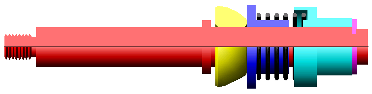
Ive coloured the components for clarity. The red part is the shaft, the yellow part is the steel elbow joint, the blue part is the upper spring keeper, the black section is the spring, the green section is the lower spring keeper/micro switch actuator and the pink part is the e-clip.
My solution has gone through quite a few changes and is likely to change very slightly again (dimensionally) but this is how the shaft assembly should look.
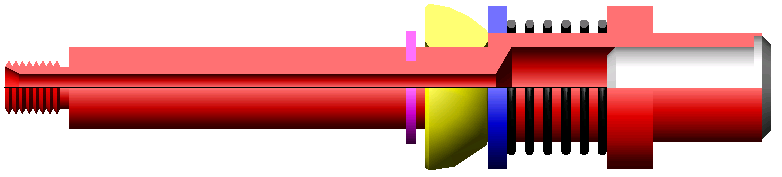
The 4-pole sockets I'm using require a mounting hole of 9mm. The standard shaft is 9mm so I had to enlarge the lower shaft to 12mm so it can house the socket. The only problem with this was that the shaft is normally inserted into the joystick base from the top and has to pass through the 9.05mm elbow joint and so the larger 12mm section would not pass though. I solved this by moving the e-clip to the left of the elbow joint so the shaft can be inserted from the bottom.
I have also taken the upper spring keeper and lower spring keeper/micro switch actuator out of the equation to allow the socket to be housed. Ive built the lower spring keeper/micro switch actuator into the shaft. It does not need the hood as its only in place on the standard shaft to keep the spring central as the standard shaft diameter is much smaller than the 'bore' of the spring. The increased lower shaft diameter will now keep the spring central.
The upper spring keeper will be replaced with a more basic nylon washer which will allow extra room for the socket and also for extra wiring clearance. Once again, it does not need the extra section of the standard spring keeper as the increased shaft diameter will keep it central.
Well that's the plan anyway. I'm off on holiday (vacation

) for two weeks in a couple of days so I'm going to get a prototype made when I get back.
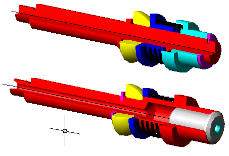
EDIT: Added another view if it helps to visualise it.


 Home
Home Help
Help Search
 Login
Login Register

 Send this topic
 Print
Print Topic: For Sale: Hollow joystick shafts, LED Lit for Sanwas/T-Sticks + More (Read 13984 times)


