OK, here's the directions for the construction and assembly process I recommend.
Step 1, machine the perimeter boards.
Starting with a 4' length of 1"x4" board (really 3/4" x 3-1/2") rip the board down to 3-1/16" (changing the dimension here will allow you to use a deeper joystick or make a more compact CP if you do some careful planning, but this measurement will allow for an omni-stick or a U360 and maybe others. Changing this dimension also changes the distances in the upcoming directions so you will have to adapt on your own.)
Now that the board is ripped to the correct width it is time to put in the rabbet and dado. In the following instructions I will include a drawing of what the board should look like from the end once the step is complete. I recommend using a test piece to check your blade depth and other saw settings as you progress. Alternative techniques for the rabbet and dado would be to use a dado blade in the table saw or to use a router, but I think that either choice would require more setup than it is worth for a project this size.
Set your blade depth on the table saw to 1/4" and set the fence at 2-3/4" and run the board through leaving a slot in the underside of it like this:

Now bump your fence over about 1/16" further and run the board again, making the slot a little wider and working your way towards the edge of the board:

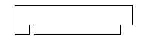
Repeat the last step until you have made a complete rabbet to the edge of the board that looks like this:

Next we will make the dado for the CP top to slide into. Turn the board around so that the side that was just against the fence is out by the blade like this:

Set the fence so that the space between it and the blade is 2-9/16" and leave the depth set to 1/4" and make another pass with the board:
Now move the fence so that the distance from it to the
far side of the blade is 2-13/16" and make a pass, this may leave a little feather of wood between the last 2 cuts, if it does then bump the fence back toward the blade a little more than 1/16" and do another run, you should end up with a piece that looks like this:

The next step can either be done now or once the box is assembled, but in all my drawings it makes it look like it was done at this point so that's what I'll show. Using a 1/4" round-over bit in a router soften the edge of the board:

Step one is complete, you should now have a board that looks something like this:

Step two is to cut the boards to length. For this step I used a chop saw, but you could use a radial arm saw, a miter box, or even do this with a crosscut set-up on a table saw with the blade tilted. Because there are so many ways to make these cuts and all of them will basically work the same I'll just say this... Cut the 4 sides of the box to length with a 45 degree miter at the ends.

Step 3 is to cut the MDF for the bottom of the box and the CP top. Both pieces are the same size 8-1/2"x10". Again cut these however you want, just cut them the right size and cut them with square corners and you'll be good to go.

Step 4 is building the bottom of the box. Take the 2 short box sides and one long side and the MDF bottom piece and assemble as shown. I would use brads and glue for this step, but if you wanted to get fancy you could biscuit the corners.

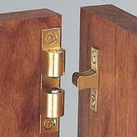
Step 5 is to dril (or notch) the cable hole, and mount the ball catches to the sides. If your choice of encoder allows you to feed the cable through a little hole then you can simply drill a hole in the back side of the box and soften the edges to keep the cable from wearing. I had to use a USB cable that wouldn't fit through the hole so I drilled a hole and then made cuts connecting it to the bottom of the box. The ball catches can be tough to properly align, but be patient, having these fit nicely is what makes it very hard to tell how the box was assembled, the catch should be placed so that it holds the back on tight and aligned. The catches should be oriented toward each-other like this:
Here's the back about to snap onto the main part of the box with the catches and the hole:

Step 6 is to drill the remaining piece of MDF for the buttons and the joystick. Using the template provided and either a spade bit, hole saw, or forstener bit drill the 1-1/8" holes and using a 3/16" or 1/4" twist drill bit drill the mounting holes. Once the joystick mounting holes are drilled countersink them so that you can use flat-head bolts to mount the joystick and hide them behind the art and acrylic:

Step 7 is mounting the recently drilled CP top to the back board of the box. With the board and the MDF carefully aligned, glue and brad the board into the slot. I would shoot the brads through the MDF into the board at a sharp angle down, toe-nailing it. You could also skip this step, my DorkStick CP doesn't have the top attached to the back because the top is acrylic and I couldn't use brads, and it works fine.

Step 8 is quite simple... slide the back and lid into the main part of the box. This is also a good time to use the round-over bit to soften the four corners of the sides:

Step 9 is one that worries many people and causes much grief. I have always had access to table saws with sharp blades and rarely have a problem cutting acrylic with them, some people use other techniques, but the table saw is my recommendation. Cut the acrylic to size, 8"x10". My renderings show the acrylic with the paper removed for clarity, but I suggest leaving it on until you are ready to start final assembly of your CP.

Step 10 is another tricky one. To cut the holes into the acrylic the cleanest and most trouble-free approach is to us a router. In order to use a flush cutting router bit on this project you will need some starter holes in the acrylic, I suggest clamping the acrylic to a piece of wood and using a slightly dull drill bit (or ideally an acrylic cutting bit) at a high speed in a drill press. Some people advocate using drills in reverse but I've never needed to. After drilling some holes that are big enough for the flush trim router bit to go through put the acrylic into the box top. Using some double-stick tape or carefully placed clamps put the acrylic into the top of the box. Now with the depth of the router set so that the bearing rides on the MDF CP lid route each hole for the buttons and the shaft of the joystick. Do not drill the joystick mounting holes through the acrylic, they won't be needed to hold the acrylic down and it will look nicer to not have the bolt heads showing.
Here is an interesting read about the best practices when drilling acrylic.
Step 11 (or twelve by my rendering titles) is fairly basic, now that you have the holes drilled remove the tape or clamps that are holding the acrylic to the rest of the CP. Mount the joystick base to the MDF and then use the buttons to hold the acrylic to the MDF. Finish assembling your joystick and your ready for wiring up:

Finally your finished. Of course at this stage you could pull the whole thing back apart and fill the brad holes, sand and finish the wood, but then you'd have to wait to play. You can also print up some custom artwork on your printer or at a photo shop and put it between the acrylic and the MDF. There are obviously a lot of ways you could take this project at this point, but that's the fun Building
Your Own Arcade Controls. Make them personalized, and be proud of what you've built:

Again, if you build a box from my plans, or a variation of them, please post some pics here, I'd love to see what people do with this. Also, if the directions aren't enough to give you the confidence to build a CP yourself or you don't have the tools, shoot me a PM and I'll see if I can crank on out for you. I'd probably build the first one of these for the cost of the materials alone so that I'd have some actual photos for the thread and I could work out any bugs.


 Home
Home Help
Help Search
 Login
Login Register

 Send this topic
 Print
Print Topic: Some plans and directions for a 1 player CP (Read 17488 times)


