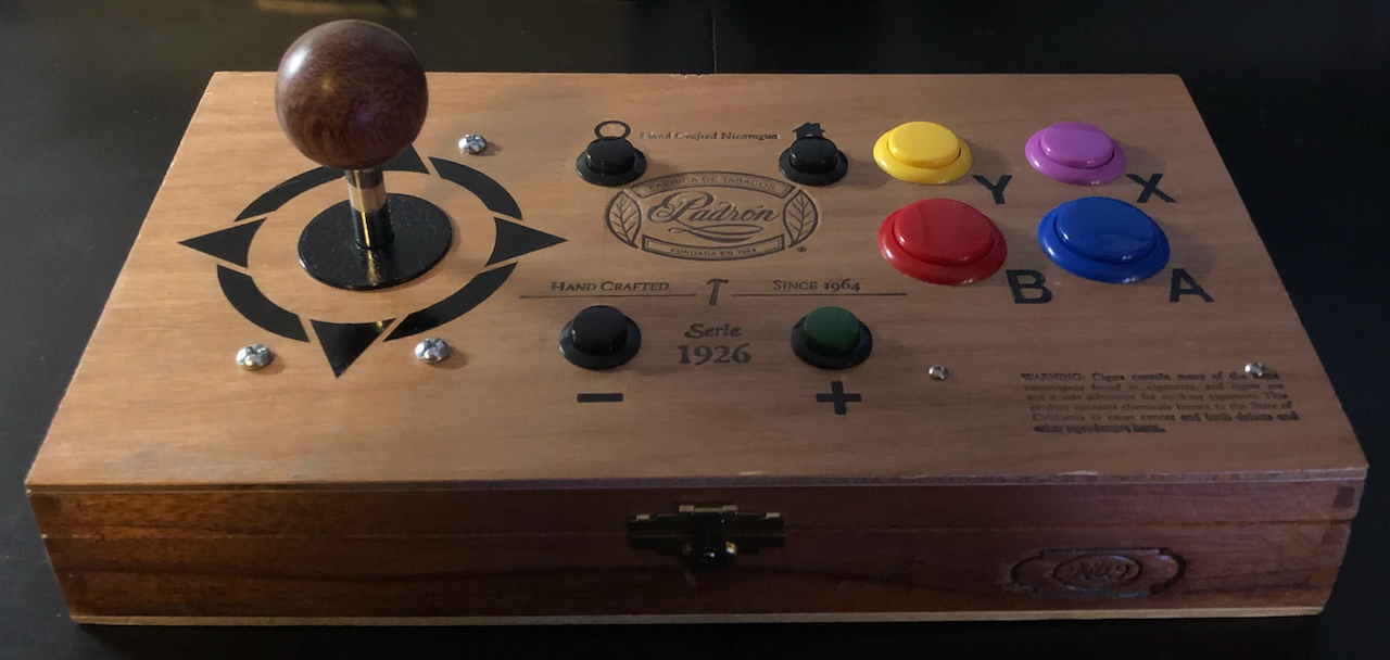
I don't have room for an arcade cabinet, so I wanted an Arcade-style game controller that I could use with Mister FPGA, MAME and Nintendo Switch. I wanted all "digital" inputs inputs whose analog signals can be trivially converted to digital (i.e. no thumbsticks, no potentiometers). I also wanted enough of them to cover all important functions on a modern console. Furthermore, the A and B buttons had to line up with the directional control in a row, just like they did on the Vs. Super Mario Bros. machine in that weird side room off the convenience store when I was a kid.
Here are my combination Build Notes / Instructions to Make Your Own.
Parts Used- 11.25" × 6.25" × 2" Cigar Box (from ebay)
- AWG Wire with .110 Quick Disconnect (from FocusAttack.com)
- Sanwa JLF-TP-8YT Original Joystick (from Sanwa Store on Amazon)
- 24mm and 30mm Sanwa Denshi Solid Color Pushbuttons (from ArcadeShock.com)
- Starelo 5pcs 12mm Momentary Push Button Switch Silver Shell with pre-Wiring (from Amazon)
- 16mm Panel Mount Momentary Pushbuttons (from Adafruit)
- Samducksa Bubinga Wood 35mm Balltop (from FocusAttack.com)
- 2 Teensy LCs (from PJRC.com)
- Perma-Proto Half-sized Breadboard PCB (from Adafruit)
- HVAZI Metric M2.5 304 Stainless Steel Button Head Socket Cap Screws Nuts Assortment Kit (from Amazon)
- binifiMux 100pcs M2.5 x 0.45mm 304 Stainless Steel Nylock Self Locking Nuts (from Amazon)
- Micro B Round Panel Mount Extension Cable - 30cm (from Adafruit)
- Long Male USB Micro B to Male USB-A Cable (from Amazon)
- various 2.54mm/0.1" Pitch Terminal Blocks (from Adafruit)
- Chartpak Self-Adhesive Vinyl Capital Letters and Numbers, 1/2 Inches High, Black (from Amazon)
- Additional Decals (from SlammedNiss here on ArcadeControls.com http://forum.arcadecontrols.com/index.php/topic,130477.0.html)
- Solder
- Flux
- hookup wire
- hot glue sticks
Tools Recommended- Safety Glasses
- Multi-size wire stripper & cutter (Part 5023 from Adafruit)
- Copper Wire-cutters
- Craftsman Aviation Snips, Straight Cut
- Metal Metric Ruler
- Engineers Square
- Soldering Iron
- Hand Drill and/or Drill Press with Cone Step Drill Bit
- Wood Clamp
- Dremel Tool with Drum Sander attachment
- Craft Knife
- Hot Glue Gun
- Multimeter
ConstructionCaseI don't like drilling into metal and I'm not crazy about plastic, either. That left wood and wood composites.
A survey of eBay and Etsy revealed a lot of cool-looking cigar boxes, but few with workable dimensions. I needed one wide enough to fit comfortably on a lap, but also high enough to accommodate a joysticks under-mechanism.
I settled on a Padron Serie 1926 No. 9, with dimensions 11.25" × 6.25" × 2" (28.575 cm × 15.88 cm × 5.08 cm).
JoystickThe clicky Sanwa joystick came with a removable bracket that enabled me to convert it from 8-way to 4-way. That's a better fit for many retrogames, some of which were originally played using a D-Pad.
I later splurged and purchased a Samducksa Bubinga Wood 35mm Balltop for it.
DrillingI found that pencil erased cleanly from the surface of the cigar box, which permitted me to trace out drill points ahead of time with a ruler and an engineers square.
Always wear safety glasses while drilling!
Luckily, the lid of the box proved to be made out of some wonderful wood composite material that drilled easily with both conventional and stepped code bits.
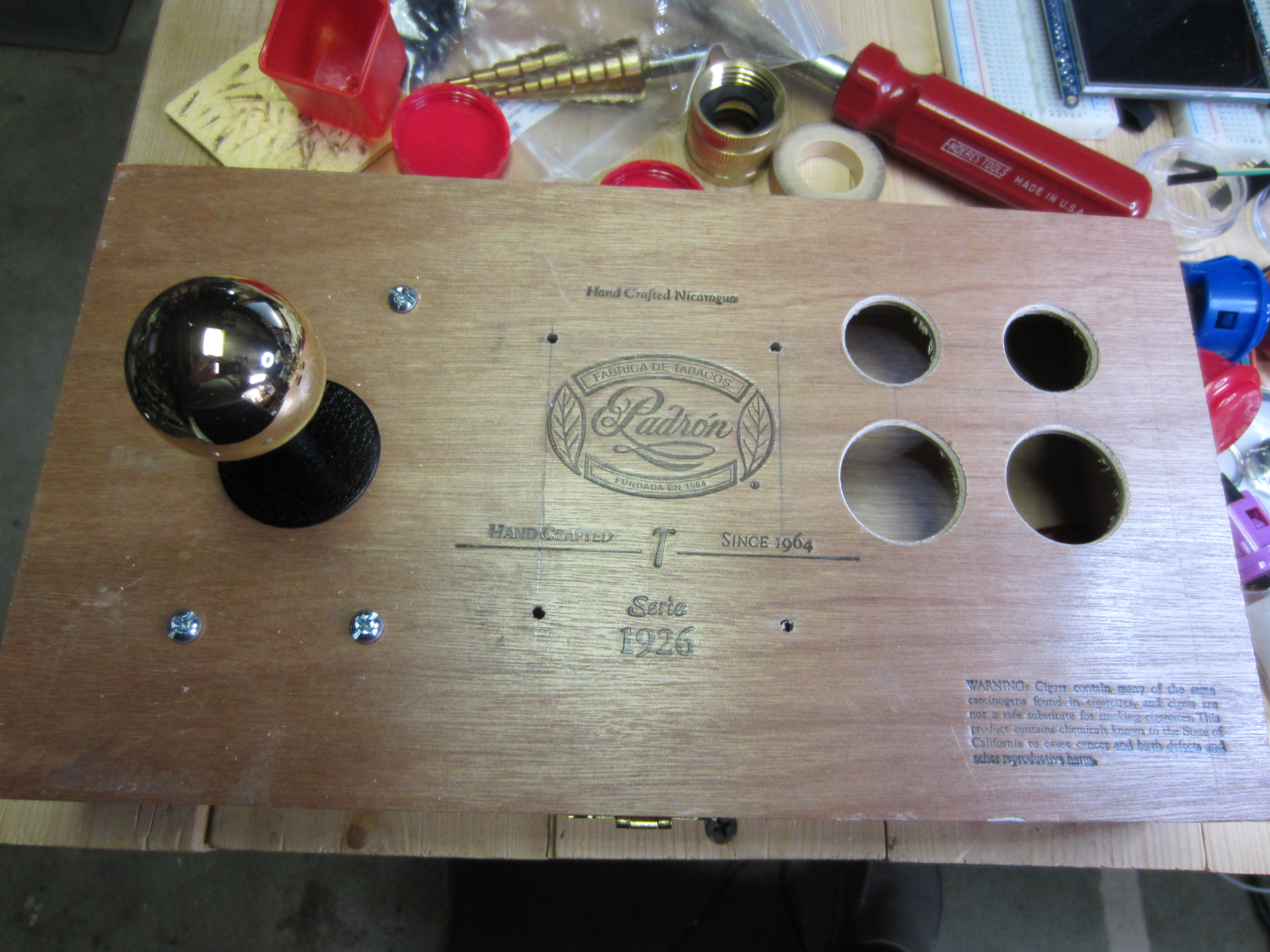
I was not so fortunate with the back of the box. It appeared to be a laminate of two very different woody materials. Drilling it was very difficult. To make matters worse, the breadth of the box prevented me from standing the box up on end under my drill press with large bits installed. I basically had to construct a makeshift stand, then get bores started with a step cone bit on my hand drill, and finally widen them gradually to the required diameter using the barrel attachment on my Dremel tool.
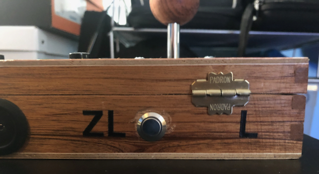
I strongly advise against the use of conventional drill bits for anything other than screw holes! I made kind of a mess out of the ZR button before retiring them.
SolderingIm not going to go into a lot of detail here other than to encourage the liberal use flux and terminal blocks! Also: take your time, check your work with a multimeter, and make sure that your work area is well-ventilated.
MicrocontrollerI used the Teensy Microcontroller because they are extremely easy to use as a USB client device and Ive had nothing but good experiences with them. In particular, I selected Teensy LC, because they're cheap (LC = "low cost"!)
I soldered a socket to a proto-board, and then soldered-in terminal blocks. This freed me to iterate on the wiring without the need for desoldering, which is terrible and to be avoided whenever possible.
With all the buttons installed, there wasn't room for much else so I put on safety glasses and used tin snips to remove the redundant positive/negative terminal rows from the proto-board.
After penciling out targets, I drilled narrow bores into the cigar box lid and secured the proto-board with M2.5 screws and Nylocks.
I cut the input wires to size and used the excess cabling for other interconnections.
I didn't have a screwdriver tiny enough, so I operated the terminal block screws with my craft knife.
USB ConnectorI really didnt want a messy long cable permanently hanging off the back of my controller, so I decided to install a rear USB cable socket.
Even though the Teensy microcontroller that would power the device uses USB Micro-B, I initially had hoped to install a USB-C port, connected with an adapter. I figured that would be more secure. But there were two problems:
- I couldnt find one with a small enough diameter to fit comfortably into the side of the lid
- It turns out the USB spec forbids the very existence of USB-C adapters (!) I think there is some reversibility issue.
So, I ended up (carefully) setting a USB Micro-B port in there. Micro-B ended up being adequately snug. Even so, the external Male-to-male cable should never be in tension during use. If you find that it is, go get a longer cable.
Fitting the port into the bore in the back of the box did prove to be a bit of a challenge, given the limited clearance
I had to cut some of the rubber sheath off the adapter with copper wire-cutters. In the process, I nearly cut thru the entire sheath. Luckily, it held under compression once screwed-in!
 Firmware
If you want it to work on Nintendo Switch, save yourself a lot of headaches and just use
https://github.com/gdsports/NSGadget_TeensyYou will want to modify their Gamepad example to turn off the Analog Stick. Delete or comment-out the axisRead function, and everything that calls it.
I tried to keep the default button/pin assignments suggested in the project README, but be sure to make edits for any departures.
If you dont care whether it works on Nintendo Switch, you can just configure the Teensy as a Joystick (the USB Type you want is Keyboard + Mouse + Joystick) and use a short Arduino IDE sketch along the lines of this:
void setup()
{
  pinMode(2, INPUT_PULLUP);
  pinMode(3, INPUT_PULLUP);
  pinMode(4, INPUT_PULLUP);
  pinMode(5, INPUT_PULLUP);
  pinMode(6, INPUT_PULLUP);
}

void loop()
{
  int up = !digitalRead(2);
  int right = !digitalRead(5);
  int down = !digitalRead(3);
  int left = !digitalRead(4);

  int punch = !digitalRead(6);

  if (up && !down)
  {
    if (left && !right)
    {
      Joystick.hat(315);
    }
    else if (right)
    {
      Joystick.hat(45);
    }
    else
    {
      Joystick.hat(0);
    }
  }
  else if (down && !up)
  {
    if (left && !right)
    {
      Joystick.hat(225);
    }
    else if (right)
    {
      Joystick.hat(135);
    }
    else
    {
      Joystick.hat(180);
    }
  }
  else if (left && !right)
  {
    Joystick.hat(270);
  }
  else if (right && !left)
  {
    Joystick.hat(90);
  }
  else
  {
    Joystick.hat(-1);
  }

  Joystick.button(3, punch);

  Joystick.X(512);            // "value" is from 0 to 1023
  Joystick.Y(512);            //   512 is resting position
  Joystick.Z(512);

  delay(50);
}
(adding in buttons as needed)
DecalsI used Chartpak letter decals to label the A, B, X, Y, L, R, ZL and ZR buttons. They have a nice texture that resembles the the texture of the cigar box engravings.
SlammedNiss's joystick wrapper and custom Joy-Con-style icon decals provided a great finishing touch. I had a little trouble getting the clear transfer material to separate, and ended up sort of forcing it to stay down with my craft knife. SlammedNiss suggested that some surface finishes can cause this difficulty.
Touch-Sensitivity (!)I wired the cigar box's brass hinges to be touch-sensitive and used them as shoulder buttons!

Soldering wires to the interior hinge staples was very difficult, and required several attempts. Once I was finally happy with it, I further secured the connections with hot glue.
The Teensy LC and Teensy 3 have hardware-level capacitance touch-sensitivity built-in on certain pins (see the included pinout card to determine which), but the resulting signal noise can interfere with digital reads on neighbor pins. Consequently, I drafted a
second Teensy LC to collect touch signals from the shoulder buttons and relay them to the main Teensy.
This also reconciles NSGadget_Teensy with the default
touchRead operation, which involves a blocking delay which would slow down scans of the other inputs. Despite that, I ended up switching to Bryan42's no-delay variant of
touchRead that does not suffer from the problem:
https://forum.pjrc.com/threads/54527-Asynchronous-(poll-based)-touch-sensing?p=192932&viewfull=1#post192932. I don't pretend to understand it, but it seems to work.
In sketch setup, I initialized the relay pin on the main Teensy with
INPUT rather than
INPUT_PULLUP, since it doesn't need a pull-up resistor. Here's the diff for what I changed in NSGadget_Teensy's Gamepad example:
<     buttons[i].attach( BUTTON_PINS[i] , INPUT_PULLUP  );  //setup the bounce instance for the current button
---
>     uint8_t pin = BUTTON_PINS[i];
>     switch (pin)
>     {
>       case 7:
>       case 18:
>         buttons[i].attach( pin, INPUT );
>             //setup the bounce instance for the current button
>         break;
>       default:
>         buttons[i].attach( pin, INPUT_PULLUP  );  //setup the bounce instance for the current button
>     }
And then for the touch-relay Teensy sketch (let's call it
touch_relay.ino
):
#include "AsyncTouchMgr.h"

uint8_t LEFT_SHOULDER_INPUT_PIN = 19;
uint8_t RIGHT_SHOULDER_INPUT_PIN = 16;
uint8_t LEFT_SHOULDER_OUTPUT_PIN = 23;
uint8_t RIGHT_SHOULDER_OUTPUT_PIN = 21;

AsyncTouchMgr TouchMgr;

void setup()
{
  // Serial.begin(38400);
  delay(500);

  // Serial.println("Enabling pins");
  TouchMgr.EnablePin(LEFT_SHOULDER_INPUT_PIN);
  TouchMgr.EnablePin(RIGHT_SHOULDER_INPUT_PIN);
  // Serial.println("Starting scans");
  TouchMgr.StartScan(); // Kick things off

  pinMode(LEFT_SHOULDER_OUTPUT_PIN, OUTPUT);
  pinMode(RIGHT_SHOULDER_OUTPUT_PIN, OUTPUT);
}

#define THRESHOLD 4000

void loop()
{
  if (TouchMgr.Ready()) // Non blocking
  {
     int left_shoulder = TouchMgr.ReadPin(LEFT_SHOULDER_INPUT_PIN);
     int right_shoulder = TouchMgr.ReadPin(RIGHT_SHOULDER_INPUT_PIN);

     if (left_shoulder > THRESHOLD)
     {
        Serial.println("Left shoulder activated");
        digitalWrite(LEFT_SHOULDER_OUTPUT_PIN, LOW);
     }
     else
     {
        Serial.println("Left shoulder NOT activated");
        digitalWrite(LEFT_SHOULDER_OUTPUT_PIN, HIGH);
     }

     if (right_shoulder > THRESHOLD)
     {
        Serial.println("Right shoulder activated");
        digitalWrite(RIGHT_SHOULDER_OUTPUT_PIN, LOW);
     }
     else
     {
        Serial.println("Right shoulder NOT activated");
        digitalWrite(RIGHT_SHOULDER_OUTPUT_PIN, HIGH);
     }

     TouchMgr.StartScan(); // For next time 'round
  }
  else
  {
     Serial.println("Not ready!");
  }

  delay(10);
}
Again, using Bryan42's touchRead variant. You may find it easier to just use the default version, which won't require you to change Arduino library files.
I had some little Pimoroni stickers left over from another project, and attached them to the Teensy microprocessors to avoid confusing them. (And I guess also to serve as extremely ineffective heat sinks.)


 Home
Home Help
Help Search
 Login
Login Register

 Send this topic
 Print
Print Topic: Guardabarranco Arcade-Style Game Controller (Read 1059 times)


