Main Restorations Software Audio/Jukebox/MP3 Everything Else Buy/Sell/Trade
Project Announcements Monitor/Video GroovyMAME Merit/JVL Touchscreen Meet Up Retail Vendors
Driving & Racing Woodworking Software Support Forums Consoles Project Arcade Reviews
Automated Projects Artwork Frontend Support Forums Pinball Forum Discussion Old Boards
Raspberry Pi & Dev Board controls.dat Linux Miscellaneous Arcade Wiki Discussion Old Archives
Lightguns Arcade1Up Try the site in https mode Site News

Unread posts | New Replies | Recent posts | Rules | Chatroom | Wiki | File Repository | RSS | Submit news


Author Topic: Trackball Resolution  (Read 2385 times)

0 Members and 1 Guest are viewing this topic.

Ropi Jo

  • Trade Count: (0)
  • Full Member
  • ***
  • Offline Offline
  • Posts: 201
  • Last login:January 30, 2024, 04:26:37 pm
  • I want to build my own arcade controls!
Trackball Resolution
« on: October 17, 2022, 03:45:15 pm »
I'm trying to calculate the resolution needed for a trackball in Mame.

My spinners are 1200ppr which I'm sure I read somewhere was correct, or close enough.

The trackball however has a 2 1/4" diameter pool ball, turning against a 5mm shaft, so there's a big ratio.

Some basic maths will tell me the ratio, and I'm assuming 1200 is the target.

Am I correct in thinking that as it will be quadrature each hole in the wheel will actually be 2 pulses?

This will be fed into the optopac, same as the spinners.

Am I on the right track or miles off?

This is all being 3D printed so I can trial and error but I'd like to be fairly close to start with.
« Last Edit: October 17, 2022, 03:49:28 pm by Ropi Jo »

PL1

  • Global Moderator
  • Trade Count: (+1)
  • Full Member
  • *****
  • Offline Offline
  • Posts: 9404
  • Last login:Today at 03:14:06 am
  • Designated spam hunter
Re: Trackball Resolution
« Reply #1 on: October 18, 2022, 12:04:33 am »
I'm trying to calculate the resolution needed for a trackball in Mame.
That can be a difficult thing to wrap your head around and work through.

The wiki entry is not as clear as it could be regarding trackballs, but near the top there are links to three related threads that provide more info.

http://wiki.arcadecontrols.com/index.php/Spinner_Turn_Count

My spinners are 1200ppr which I'm sure I read somewhere was correct, or close enough.
That is the resolution of the TT2 and SpinTrak spinners.
- Unless you're using those spinners to generate your trackball X- and Y-axis quadrature waveforms that fact isn't relevant to what you are trying to do.

The trackball however has a 2 1/4" diameter pool ball, turning against a 5mm shaft, so there's a big ratio.
Yeah, that's almost double the ratio of the standard Happ 2-1/4 trackball with a 0.362 inch (9.1948 mm) roller and a 24 tooth encoder wheel.

One thing to watch out for is if that ratio gets too high, the encoder wheel might turn so fast that you get backspin.
- See post here for more detailed info about backspin.

Some basic maths will tell me the ratio, and I'm assuming 1200 is the target.
Don't assume that 1200 is the target.

AFAIK that's the resolution chosen for the TT2 and SpinTrak spinners so they would be be a suitable replacement for all spinners including the geared ones for Arkanoid.

Most spinners and trackballs are much lower resolution.

Am I correct in thinking that as it will be quadrature each hole in the wheel will actually be 2 pulses?
Assuming you have a properly paired encoder wheel and opto spacing, quadrature waveforms have 4 phases per tooth/gap.
- The good spacing image shows the encoder wheel at the left edge of Phase 1.
- Data line A is transitioning from high (not blocked) to low (blocked) and data line B is in the middle of being blocked.
- As you rotate the encoder wheel clockwise, the blocking and un-blocking of the optos will produce the quadrature waveforms shown.

This is all being 3D printed so I can trial and error but I'd like to be fairly close to start with.
Get the encoder wheel and opto spacing right then you can adjust the sensitivity in MAME.
- I'm guessing you plan to use Happ Red Boards instead of trying to design your own optical circuit, right?


To work out the correct opto spacing and encoder wheel measurements:

- Calculate the number of degrees for each tooth/gap on your encoder wheel.  For example, a 24 tooth encoder wheel ==> one 360 degree rotation of the wheel is divided into 24 teeth + 24 gaps ==> each tooth and each gap is 7.5 degrees wide. (360/48 = 7.5)

- How many teeth gap between optos?  The image above shows a 2.5 tooth gap. (2.5 * 7.5 = 18.75 degree gap angle)
-- More info about this gap value here.

- Use the known distance between the optos and the gap angle to calculate the radius from the center of the shaft to the opto position.
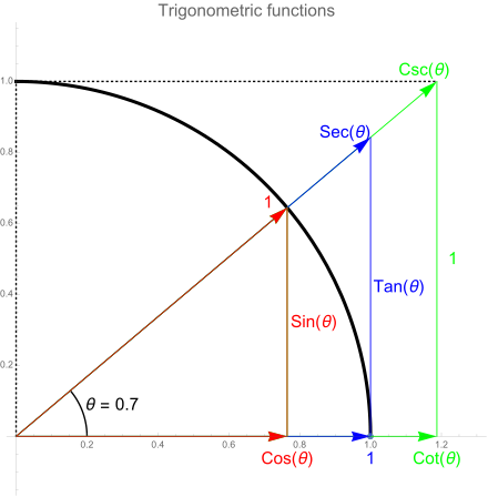
-- Split the triangle defined by the two optos and center of the shaft into two right triangles.
-- You know the gap angle and the distance between optos so divide those values by two and apply them to the angle (θ) and "opposite" of one of the right triangles then use the sine trigonometic function to solve for the hypotenuse which is the radius from the center of the shaft to the opto position.


Scott
« Last Edit: October 18, 2022, 12:22:20 am by PL1 »

Ropi Jo

  • Trade Count: (0)
  • Full Member
  • ***
  • Offline Offline
  • Posts: 201
  • Last login:January 30, 2024, 04:26:37 pm
  • I want to build my own arcade controls!
Re: Trackball Resolution
« Reply #2 on: October 18, 2022, 08:11:12 am »
That is brilliant Scott.

Thanks for taking the time to include so much detail.

PL1

  • Global Moderator
  • Trade Count: (+1)
  • Full Member
  • *****
  • Offline Offline
  • Posts: 9404
  • Last login:Today at 03:14:06 am
  • Designated spam hunter
Re: Trackball Resolution
« Reply #3 on: October 18, 2022, 10:03:16 am »
Glad to assist.   :cheers:


Scott

Ropi Jo

  • Trade Count: (0)
  • Full Member
  • ***
  • Offline Offline
  • Posts: 201
  • Last login:January 30, 2024, 04:26:37 pm
  • I want to build my own arcade controls!
Re: Trackball Resolution
« Reply #4 on: October 18, 2022, 03:29:56 pm »
Get the encoder wheel and opto spacing right then you can adjust the sensitivity in MAME.
- I'm guessing you plan to use Happ Red Boards instead of trying to design your own optical circuit, right?


I was planning to simply run optos directly to the opti pac with a current limiting resistor on each opto.

Is this not such a good idea?

Ropi Jo

  • Trade Count: (0)
  • Full Member
  • ***
  • Offline Offline
  • Posts: 201
  • Last login:January 30, 2024, 04:26:37 pm
  • I want to build my own arcade controls!
Re: Trackball Resolution
« Reply #5 on: October 18, 2022, 04:21:26 pm »
Yeah, that's almost double the ratio of the standard Happ 2-1/4 trackball with a 0.362 inch (9.1948 mm) roller and a 24 tooth encoder wheel.

Reading what you say about backspin it would seem I need to think about the ratio a little more.

We are going to print a sleeve for the 5mm shaft to go between the bearings. This will bring the shaft to 10mm, and then we'll print a 24 tooth wheel.

This should bring us quite close to your example.

PL1

  • Global Moderator
  • Trade Count: (+1)
  • Full Member
  • *****
  • Offline Offline
  • Posts: 9404
  • Last login:Today at 03:14:06 am
  • Designated spam hunter
Re: Trackball Resolution
« Reply #6 on: October 18, 2022, 08:05:45 pm »
Get the encoder wheel and opto spacing right then you can adjust the sensitivity in MAME.
- I'm guessing you plan to use Happ Red Boards instead of trying to design your own optical circuit, right?


I was planning to simply run optos directly to the opti pac with a current limiting resistor on each opto.

Is this not such a good idea?
Your idea should work fine at low speeds, but it probably won't work at high speeds.

The Red Board is a bit more complex than just 2 optos and 2 resistors.


Without the correct circuit design and balance of component values, you are more likely to run into problems like backspin at high speed due to high frequency roll off.

As you go faster, the high/low pulses of the quadrature waveforms become more narrow (higher frequency) but it still takes the same amount of time to transition between logic high and low.

If the transition time is too long compared to the pulse width, the optical (mouse) encoder won't have enough time to register the change in logic levels.


Yeah, that's almost double the ratio of the standard Happ 2-1/4 trackball with a 0.362 inch (9.1948 mm) roller and a 24 tooth encoder wheel.

Reading what you say about backspin it would seem I need to think about the ratio a little more.

We are going to print a sleeve for the 5mm shaft to go between the bearings. This will bring the shaft to 10mm, and then we'll print a 24 tooth wheel.

This should bring us quite close to your example.
The trackball riding on a printed sleeve is going to be a problem due to wear.
- There's a reason the wiki lists the trackball ratios with the caveat "(no wear)".   ;)

Use a hardened 8mm or 10mm shaft instead.


Scott

Ropi Jo

  • Trade Count: (0)
  • Full Member
  • ***
  • Offline Offline
  • Posts: 201
  • Last login:January 30, 2024, 04:26:37 pm
  • I want to build my own arcade controls!
Re: Trackball Resolution
« Reply #7 on: October 19, 2022, 08:35:01 am »
Ah... so the red board will 'square-up' the square wave from the opto, which I assume is already on the red board. That makes sense.

I wonder where do I buy those in the UK?

I have a cunning plan.... the 1200ppr encoders I used for the spinners.... I have more of those. They are very expensive industry standard encoders that I had left over from a project years ago but cost me nothing and they are not planned to be used anytime in the future. Perfect square wave at rediculously high speeds. I wonder if I can break into them and utilise the electronics. Wire my optos in place of the onboard optos? I'll need to investigate.

Thanks again for the info.

Ropi Jo

  • Trade Count: (0)
  • Full Member
  • ***
  • Offline Offline
  • Posts: 201
  • Last login:January 30, 2024, 04:26:37 pm
  • I want to build my own arcade controls!
Re: Trackball Resolution
« Reply #8 on: October 19, 2022, 02:38:58 pm »
And.. we do have 8mm shaft and bearings so we'll go with that.

My son left the 5mm parts printing before leaving for work this morning and assembled them once home (not the sleeves I mentioned) so the ball is turning directly against the 5mm shafts.

The resistance due to the high ratio is not great. The ball does not run on after a spin and just doesn't feel too great. And it's definitely slipping against the shaft.

He'll re-design for the 8mm and we'll give that a go.

PL1

  • Global Moderator
  • Trade Count: (+1)
  • Full Member
  • *****
  • Offline Offline
  • Posts: 9404
  • Last login:Today at 03:14:06 am
  • Designated spam hunter
Re: Trackball Resolution
« Reply #9 on: October 19, 2022, 02:57:20 pm »
Ah... so the red board will 'square-up' the square wave from the opto, which I assume is already on the red board. That makes sense.
Yes, faster switching between logic levels means the rounded parts on the leading and trailing edges are not as long so more of the pulse width registers as logic high/low.

The optos are easier to see in this picture.
- They will work with a standard 24-tooth encoder wheel.


I wonder where do I buy those in the UK?
Not sure.  Try search terms "A052-1011-00" or "Happ Red Board".

I have a cunning plan.... the 1200ppr encoders I used for the spinners.... I have more of those. They are very expensive industry standard encoders that I had left over from a project years ago but cost me nothing and they are not planned to be used anytime in the future. Perfect square wave at rediculously high speeds.
Ridiculous is the operative word here.   ::)

Replacing a 24 ppr encoder wheel and optos with a 1200 ppr encoder means increasing the frequency by 50x.
- Way too fast.
- Way too sensitive.
- No optical (mouse) encoder could keep up with it even if you're rolling the trackball at 1/4 speed.

I wonder if I can break into them and utilise the electronics. Wire my optos in place of the onboard optos?
Haven't seen the encoders you're talking about, but I assume the answer is a resounding NO.

High resolution encoders might output quadrature waveforms, but they use very different components than trackballs.

Picture trying to print a 1200 tooth encoder wheel (360 degrees / 1200 teeth + 1200 gaps ==> 0.15 degrees per tooth) and perfectly align the optos so they are X + 0.5 teeth apart, but even if you could do that, the LED in the opto won't be blocked by those narrow teeth so you'll have a constant logic high.


Scott

Ropi Jo

  • Trade Count: (0)
  • Full Member
  • ***
  • Offline Offline
  • Posts: 201
  • Last login:January 30, 2024, 04:26:37 pm
  • I want to build my own arcade controls!
Re: Trackball Resolution
« Reply #10 on: October 19, 2022, 03:21:15 pm »
I'm not suggesting using the 1200 wheel or the optos in the 1200 encoder. Just wiring my optos in place of them and using the 24 tooth wheel.

I won't know till I crack them open if it's possible.

PL1

  • Global Moderator
  • Trade Count: (+1)
  • Full Member
  • *****
  • Offline Offline
  • Posts: 9404
  • Last login:Today at 03:14:06 am
  • Designated spam hunter
Re: Trackball Resolution
« Reply #11 on: October 19, 2022, 04:04:32 pm »
I'm not suggesting using the 1200 wheel or the optos in the 1200 encoder. Just wiring my optos in place of them and using the 24 tooth wheel.

I won't know till I crack them open if it's possible.
Don't bother cracking them open because there's nothing in there that you can wire to trackball-style optos and align those optos with an encoder wheel . . . or did you miss the part where I explained the engineering reasons why it's absolutely not possible to mix and match the two types of hardware.
- Different methods for producing quadrature waveforms.
- Different hardware.
- Different specs.

If you want try using trackball-style optos, just build your own optical board on perf board.
- Check the opto spec sheet to see if there's a sample circuit design for optimal performance.


Scott

Ropi Jo

  • Trade Count: (0)
  • Full Member
  • ***
  • Offline Offline
  • Posts: 201
  • Last login:January 30, 2024, 04:26:37 pm
  • I want to build my own arcade controls!
Re: Trackball Resolution
« Reply #12 on: October 19, 2022, 04:09:14 pm »
Understood. Cheers Scott.

Ropi Jo

  • Trade Count: (0)
  • Full Member
  • ***
  • Offline Offline
  • Posts: 201
  • Last login:January 30, 2024, 04:26:37 pm
  • I want to build my own arcade controls!
Re: Trackball Resolution
« Reply #13 on: October 21, 2022, 03:54:30 pm »
Trackball has been redesigned and reprinted. Mechanically it works a treat.

Plan is to print the encoder wheels and spin them up connected to a scope and see if I get the effect Scott described at high speed.

There are no options to purchase the happ red boards in the UK that I can find, and searches for circuitry to do the same thing are proving fruitless.

My 1200 encoder modding thoughts were rightly and savagely slaughtered (Thanks Scott!).

So my next thought...

If I hack an optical mouse to see the ball movement, connected to a USB socket, would this seem viable?

My old mame cab had a PS2 trackball that worked flawlessly. BUT... it was permanently connected.

This build has hot swap CPs. The trackball CP will need to be hot swap-able.

I have an Ipac, Apac, and Optipac permanently connected to USB and they they do not get lost.

Would a USB mouse get lost by hot swapping?

It would make my life a damn sight easier if it wont

System runs on W7

Thank you.
« Last Edit: October 21, 2022, 04:00:42 pm by Ropi Jo »

PL1

  • Global Moderator
  • Trade Count: (+1)
  • Full Member
  • *****
  • Offline Offline
  • Posts: 9404
  • Last login:Today at 03:14:06 am
  • Designated spam hunter
Re: Trackball Resolution
« Reply #14 on: October 22, 2022, 12:46:36 am »
If I hack an optical mouse to see the ball movement, connected to a USB socket, would this seem viable?
StefanBurger used this approach several years ago for this trackball design.
http://forum.arcadecontrols.com/index.php/topic,161771.0.html


When you flip a mouse on it's back with the "tail" toward you and mount a ball over it, the X-axis works right but the Y-axis is reversed.

Reversing an axis is easy with optos -- you just swap data lines A and B.

Two possible approaches to reversing an optical mouse axis:
- The easy way is to reverse the axis in MAME. (Analog Controls -- Track Y Reverse)  Obviously, this doesn't work outside of MAME.
- The hard way is to modify the optical mouse circuit like StefanBurger did.

Would a USB mouse get lost by hot swapping?
No, assuming your trackball panel doesn't have two trackballs or a trackball and a spinner or two.
- By default, Windows adds similar axes so a mouse and a trackball can both control a single cursor.  For example, moving the mouse 5 steps right while moving the trackball 2 steps left moves the cursor 3 steps right.
- As long as you only need one of each axis for gameplay you're fine.

You can keep Windows from adding similar axes by using raw inputs ("-multimouse" option in MAME), but you might run into the Windows device renumbering issue.


Scott

Ropi Jo

  • Trade Count: (0)
  • Full Member
  • ***
  • Offline Offline
  • Posts: 201
  • Last login:January 30, 2024, 04:26:37 pm
  • I want to build my own arcade controls!
Re: Trackball Resolution
« Reply #15 on: October 23, 2022, 04:45:42 am »
Thanks again Scott.

Excuse me for being a bit thick please.


When you flip a mouse on it's back with the "tail" toward you and mount a ball over it, the X-axis works right but the Y-axis is reversed.

Reversing an axis is easy with optos -- you just swap data lines A and B.

Two possible approaches to reversing an optical mouse axis:
- The easy way is to reverse the axis in MAME. (Analog Controls -- Track Y Reverse)  Obviously, this doesn't work outside of MAME.
- The hard way is to modify the optical mouse circuit like StefanBurger did.


Scott

I'm not sure that he did mod the mouse in that way. He brings the curser to the middle of the screen using a mouse out of screen shot, and then takes over with the trackball. The curser then does not follow his trackball movements and he takes over again with the off screen mouse.

Only when he goes into mame does the trackall work as required so he must me relying on the mame settings.

Unless I'm seeing it wrong.

But, it's still great. His resolution looks miles out but assuming he can put that right in the game settings.

Intresting that some mice work better on the smooth surface than others. I've got a box of old mice so hopefully I'll find one that fits the bill.


Would a USB mouse get lost by hot swapping?

No, assuming your trackball panel doesn't have two trackballs or a trackball and a spinner or two.
- By default, Windows adds similar axes so a mouse and a trackball can both control a single cursor.  For example, moving the mouse 5 steps right while moving the trackball 2 steps left moves the cursor 3 steps right.
- As long as you only need one of each axis for gameplay you're fine.

You can keep Windows from adding similar axes by using raw inputs ("-multimouse" option in MAME), but you might run into the Windows device renumbering issue.


Scott

The 2 spinners are on another CP and wire to the optipac and work perfectly. This CP will have only the single trackball, and theres no other mice anywhere. Can you confirm if I need multimouse ON or OFF, and if the desired option will stop windows messing with the USB ports?

EDIT..... Forgot this...... for getting out of trouble if things get messed up I planned to have a bluetooth KB inside the coindoor, with built in scroll pad. The USB reciever would be permanently connected to the mobo. Would this cause any issues?

Thanks again.
« Last Edit: October 23, 2022, 04:54:10 am by Ropi Jo »

PL1

  • Global Moderator
  • Trade Count: (+1)
  • Full Member
  • *****
  • Offline Offline
  • Posts: 9404
  • Last login:Today at 03:14:06 am
  • Designated spam hunter
Re: Trackball Resolution
« Reply #16 on: October 23, 2022, 08:11:20 am »
- The hard way is to modify the optical mouse circuit like StefanBurger did.
I'm not sure that he did mod the mouse in that way. He brings the curser to the middle of the screen using a mouse out of screen shot, and then takes over with the trackball. The curser then does not follow his trackball movements and he takes over again with the off screen mouse.

Only when he goes into mame does the trackall work as required so he must me relying on the mame settings.

Unless I'm seeing it wrong.
D'oh!  You are seeing it right.  I remembered wrong.   :banghead:  :embarassed:

He didn't natively fix the inverted Y-axis.

There should be a way to natively invert the Y-axis since optical mice and optical trackballs use the same types of sensors, but doing that mod would depend on researching the specific sensor/chipset/PCB.   :dunno

Intresting that some mice work better on the smooth surface than others. I've got a box of old mice so hopefully I'll find one that fits the bill.
Most regular mice are poor candidates because the IPS (inches per second) rating is way too low.
- Related post here.

Gaming mice like the Logitech M500 or the one that StefanBurger recommended in the other thread are much better candidates.

If you want to test your various mouse and trackball combinations, I updated the parametric 3d printable testbed posted in the other thread to use hardware like this:
- 3x6x2.5mm bearings like these. (3 ea.)

- M3 x 20mm screws like these. (3 ea.)


45 and 30 degree testbed .STL files: http://forum.arcadecontrols.com/index.php?action=dlattach;topic=164992.0;attach=392227
- Haven't tried the 30 degree one, but it should be better than the 45 degree one. (less likely for the ball to fall out)

Here's the parametric OpenSCAD code in case you want to adjust the variables for trackball size, clearance, angle of contact, etc.
- To see the bearing placeholder, change "*cylinder" (disable cylinder -- doesn't include it in the render) on line 46 to "cylinder". (regular cylinder -- includes it in the render)
- To see the trackball placeholder, change "*sphere" on line 51 to "sphere".
- Disable both of these before you do the final render and output to .STL.

Code: [Select]
// Trackball Test for Roller Bearings V2 (hex base)

/////////////////////////////
//  Define variables
/////////////////////////////
TBDia = 57.15; // Trackball Diameter 2.25" = 57.15mm  3" = 76.2
VertWiggleRoom = 1; // Vertical wiggle room so TB clears base/sensor

HexRadius = 39.7; // Hex base radius
HexHeight = 11; // Hex base height
HexBlockSupportHeight = 4.5; // Hex bearing block support height
HexThick = 5;   // Hex base wall thickness

SROD = 73.7; // Support ring outer diameter
SRID = 40; // Support ring inner diameter
SRH = 3; // Support ring height

BBAngle = 30; // Bearing Block Angle (degrees below horizontal where the bearing makes contact with the trackball)
BBHeight = 4.5; // Bearing Block Height
BBDepth = 16; // Bearing Block Depth
BBWidth = 9; // Bearing Block Width
BBOffset = -3; //Bearing Block Top Offset from center
BBBaseDepth = 12; //Bearing Block Base Depth
BBBaseOffset = 20; //Bearing Block Base Offset from center

BearClear = 1; //Bearing clearance
BearID = 3.1; // Bearing inner diameter
BearOD = 6; // Bearing outer diameter
BearWidth = 2.5; // Bearing width

// Number of fragments (polygon sides) used to render a full circle.
    $fn = 180; // Default = 180  Typical range = 6 - 360
    // 6 will render a circular hole as a hexagon, 8 will render a circular hole as an octagon.
    // Lower the number for faster rendering, raise the number for smoother rendering.

/////////////////////////////
//  Make the part
/////////////////////////////

//Bearing placeholder
color("red")
translate([0, 0, TBDia/2+VertWiggleRoom])
rotate([-BBAngle, 0, 0])
translate([0, TBDia/2+BearOD/2, 0])
rotate([0, 90, 0])
*cylinder (BearWidth, d = BearOD, center=true);  // Use "*" to disable bearing placeholder
// "*cylinder" disables it rendering it invisible, "cylinder" enables it rendering it visible.

// TB placeholder
translate([0, 0, TBDia/2+VertWiggleRoom])
*sphere (d=TBDia); // Use "*" to disable TB placeholder
// "*sphere" disables it rendering it invisible, "sphere" enables it rendering it visible.

// Hex base
hull() { // Hex side 1
    rotate([0, 0, 330])
    translate([0, HexRadius, HexHeight/2+HexBlockSupportHeight/2])
    cylinder (HexHeight+HexBlockSupportHeight, d = HexThick, center=true);

    rotate([0, 0, 30])
    translate([0, HexRadius, HexHeight/2+HexBlockSupportHeight/2])
    cylinder (HexHeight+HexBlockSupportHeight, d = HexThick, center=true);
    }// End hex side 1
//
hull() { // Hex side 2
    rotate([0, 0, 30])
    translate([0, HexRadius, HexHeight/2])
    cylinder (HexHeight, d = HexThick, center=true);

    rotate([0, 0, 90])
    translate([0, HexRadius, HexHeight/2])
    cylinder (HexHeight, d = HexThick, center=true);
    }// End hex side 2
//
hull() { // Hex side 3
    rotate([0, 0, 90])
    translate([0, HexRadius, HexHeight/2+HexBlockSupportHeight/2])
    cylinder (HexHeight+HexBlockSupportHeight, d = HexThick, center=true);

    rotate([0, 0, 150])
    translate([0, HexRadius, HexHeight/2+HexBlockSupportHeight/2])
    cylinder (HexHeight+HexBlockSupportHeight, d = HexThick, center=true);
    }// End hex side 3
//
hull() { // Hex side 4
    rotate([0, 0, 150])
    translate([0, HexRadius, HexHeight/2])
    cylinder (HexHeight, d = HexThick, center=true);

    rotate([0, 0, 210])
    translate([0, HexRadius, HexHeight/2])
    cylinder (HexHeight, d = HexThick, center=true);
    }// End hex side 4
//
hull() { // Hex side 5
    rotate([0, 0, 210])
    translate([0, HexRadius, HexHeight/2+HexBlockSupportHeight/2])
    cylinder (HexHeight+HexBlockSupportHeight, d = HexThick, center=true);

    rotate([0, 0, 270])
    translate([0, HexRadius, HexHeight/2+HexBlockSupportHeight/2])
    cylinder (HexHeight+HexBlockSupportHeight, d = HexThick, center=true);
    }// End hex side 5
//
hull() { // Hex side 6
    rotate([0, 0, 270])
    translate([0, HexRadius, HexHeight/2])
    cylinder (HexHeight, d = HexThick, center=true);

    rotate([0, 0, 330])
    translate([0, HexRadius, HexHeight/2])
    cylinder (HexHeight, d = HexThick, center=true);
    }// End hex side 6
//

// Bearing Blocks
    // Bearing Block 1
difference(){ // Block hull minus Bearing Hole, Bearing Slot, and Bearing Axle Hole

    hull() { // Block hull
        translate([0, 0, TBDia/2+VertWiggleRoom])
        rotate([-BBAngle, 0, 0])
        translate([0, TBDia/2+BBHeight/2+BearClear, BBOffset])
        cube ([BBWidth, BBHeight, BBDepth], center=true); // Block face

        rotate([0, 0, 0])
        translate([0, BBBaseOffset+(BBBaseDepth/2), 0.1])
        cube ([BBWidth, BBBaseDepth, 0.2], center=true); // Block base

    } // End block hull
//
        color("white")
        translate([0, 0, TBDia/2+VertWiggleRoom])
        rotate([-BBAngle, 0, 0])
        translate([0, TBDia/2+BearOD/2, 0])
        rotate([0, 90, 0])
        cylinder (BearWidth+0.5, d = BearOD, center=true); // Bearing Hole

        color("purple")
        translate([0, 0, TBDia/2+VertWiggleRoom])
        rotate([-BBAngle, 0, 0])
        translate([0, TBDia/2, 0])
        cube ([BearWidth+0.5, BearOD, BearOD], center=true); // Bearing Slot

        color("blue")
        rotate([0, 0, 0])
        translate([0, 0, TBDia/2+VertWiggleRoom])
        rotate([-BBAngle, 0, 0])
        translate([0, TBDia/2+BearOD/2, 0])
        rotate([0, 90, 0])
        cylinder (BBWidth+0.5, d = BearID, center=true); // Bearing Axle Hole
    } // End Bearing Block 1
//
    // Bearing Block 2
    difference(){ // Block hull minus Bearing Hole, Bearing Slot, and Bearing Axle Hole

    hull() { // Block hull
        translate([0, 0, TBDia/2+VertWiggleRoom])
        rotate([-BBAngle, 0, 120])
        translate([0, TBDia/2+BBHeight/2+BearClear, BBOffset])
        cube ([BBWidth, BBHeight, BBDepth], center=true); // Block face

        rotate([0, 0, 120])
        translate([0, BBBaseOffset+(BBBaseDepth/2), 0.1])
        cube ([BBWidth, BBBaseDepth, 0.2], center=true); // Block base

    } // End block hull
        color("white")
        translate([0, 0, TBDia/2+VertWiggleRoom])
        rotate([-BBAngle, 0, 120])
        translate([0, TBDia/2+BearOD/2, 0])
        rotate([0, 90, 0])
        cylinder (BearWidth+0.5, d = BearOD, center=true); // Bearing Hole

        color("purple")
        translate([0, 0, TBDia/2+VertWiggleRoom])
        rotate([-BBAngle, 0, 120])
        translate([0, TBDia/2, 0])
        cube ([BearWidth+0.5, BearOD, BearOD], center=true); // Bearing Slot

        color("blue")
        rotate([0, 0, 120])
        translate([0, 0, TBDia/2+VertWiggleRoom])
        rotate([-BBAngle, 0, 0])
        translate([0, TBDia/2+BearOD/2, 0])
        rotate([0, 90, 0])
        cylinder (BBWidth+0.5, d = BearID, center=true); // Bearing Axle Hole
    } // End Bearing Block 2
//
    // Bearing Block 3
difference(){ // Block hull minus Bearing Hole, Bearing Slot, and Bearing Axle Hole

    hull() { // Block hull
        translate([0, 0, TBDia/2+VertWiggleRoom])
        rotate([-BBAngle, 0, 240])
        translate([0, TBDia/2+BBHeight/2+BearClear, BBOffset])
        cube ([BBWidth, BBHeight, BBDepth], center=true); // Block face

        rotate([0, 0, 240])
        translate([0, BBBaseOffset+(BBBaseDepth/2), 0.1])
        cube ([BBWidth, BBBaseDepth, 0.2], center=true); // Block base

    } // End block hull

        color("white")
        translate([0, 0, TBDia/2+VertWiggleRoom])
        rotate([-BBAngle, 0, 240])
        translate([0, TBDia/2+BearOD/2, 0])
        rotate([0, 90, 0])
        cylinder (BearWidth+0.5, d = BearOD, center=true); // Bearing Hole

        color("purple")
        translate([0, 0, TBDia/2+VertWiggleRoom])
        rotate([-BBAngle, 0, 240])
        translate([0, TBDia/2, 0])
        cube ([BearWidth+0.5, BearOD, BearOD], center=true); // Bearing Slot

        color("blue")
        rotate([0, 0, 240])
        translate([0, 0, TBDia/2+VertWiggleRoom])
        rotate([-BBAngle, 0, 0])
        translate([0, TBDia/2+BearOD/2, 0])
        rotate([0, 90, 0])
        cylinder (BBWidth+0.5, d = BearID, center=true); // Bearing Axle Hole
    } // End Bearing Block 3
//

// Support ring
difference(){ // Outer cylinder minus Inner cylinder

translate([0, 0, SRH/2])
cylinder (SRH, d = SROD, center=true); // Outer cylinder

translate([0, 0, SRH/2])
cylinder (SRH+0.2, d = SRID, center=true); // Inner cylinder
} // End difference
//

The 2 spinners are on another CP and wire to the optipac and work perfectly. This CP will have only the single trackball, and theres no other mice anywhere. Can you confirm if I need multimouse ON or OFF, and if the desired option will stop windows messing with the USB ports?

EDIT..... Forgot this...... for getting out of trouble if things get messed up I planned to have a bluetooth KB inside the coindoor, with built in scroll pad. The USB reciever would be permanently connected to the mobo. Would this cause any issues?
You aren't going to accidently nudge a spinner during trackball play or vice-versa so you should be fine with multimouse OFF which eliminates the Windows device renumbering issue.
- The possible exception is if one of your spinners is on the Z-axis and you run into the Windows scroll wheel issue where 1 step on the scroll wheel = 4(?) steps.  IIRC raw inputs (multimouse ON) eliminates the scroll wheel issue.

Having a wireless keyboard with a trackpad hidden inside the coin door only becomes a problem if a mouse (the rodent variety) starts nosing around on the trackpad while you're trying to play a game.   :lol


Scott

Ropi Jo

  • Trade Count: (0)
  • Full Member
  • ***
  • Offline Offline
  • Posts: 201
  • Last login:January 30, 2024, 04:26:37 pm
  • I want to build my own arcade controls!
Re: Trackball Resolution
« Reply #17 on: October 23, 2022, 02:28:54 pm »
Scott you are a star.

I've got no idea what that code means or even refers to. You've got to remember the computer boat sailed and left me behind years ago. My son will make more sense of it I'm sure.

Before redesigning the trackball for the 3 bearing design (instead of 3 rollers / 6 bearings and encoder wheels) we'll try all the mice we have stashed in the PC junk box.There's some gaming mice in there with switchable resolutions. Plenty to try.

I'll have to buy more filament for his 3D printer, that's for sure!

I'll give an update ASAP, and I can't thank you enough.

Did I mention you're a star?

PL1

  • Global Moderator
  • Trade Count: (+1)
  • Full Member
  • *****
  • Offline Offline
  • Posts: 9404
  • Last login:Today at 03:14:06 am
  • Designated spam hunter
Re: Trackball Resolution
« Reply #18 on: October 23, 2022, 06:16:21 pm »
Scott you are a star.
Glad to assist.   :cheers:

I've got no idea what that code means or even refers to. You've got to remember the computer boat sailed and left me behind years ago. My son will make more sense of it I'm sure.
It's OpenSCAD Constructive Solid Geometry (CSG) code that builds the part by applying math functions like union (U = addding), intersection (∩ = the overlap), and difference (- = subtracting) to basic geometric shapes like spheres, cubes, and cylinders.


You can download the OpenSCAD program here.

There's a very useful cheat sheet here with links to the user manual.

Check out this blog post for a quick overview and example of how OpenSCAD works.

The Instructable here is a must-read IMHO with info on CSG and OpenSCAD syntax that makes it easier to understand and apply the user manual.

Some quick things to understand the basics of the OpenSCAD code in this model:
- "//" indicates that the rest of the line is a comment.
- "sphere", "cylinder", and "cube" are self-explanatory.  The rest of the code on the line describes the radius, diameter, or the ([X, Y, Z]) dimensions of the shape.
- ";" is like Picard saying, "Make it so."  The semicolon tells the program to set the variable or make the shape at the current location+orientation.
- "rotate([10, 20, -30])" means rotate 10 degrees on the X-axis, 20 degrees on the Y-axis, and negative 30 degrees on the Z-axis.  If you start by looking straight forward and level, tilt your head 10 degrees up (X=10) then tilt your head 20 degrees to the right (Y=20) then turn your head 30 degrees counter-clockwise. (Z=-30)
- "translate([5, -10 ,TBDia])" means move 5mm right on the X-axis, 10mm toward you on the Y-axis, and the value of the variable "TBDia" mm up (or down if it is a negative value) on the Z-axis.
- A "hull" is like wrapping a rubber band around objects like these two cylinders.  The hull includes everything inside the rubber band, in this example the oval.


Scott

Daniel B.

  • Trade Count: (+2)
  • Full Member
  • ***
  • Offline Offline
  • Posts: 250
  • Last login:Yesterday at 09:02:49 am
  • Lightgun and Point Blank enthusiast
Re: Trackball Resolution
« Reply #19 on: December 27, 2022, 04:42:33 pm »
Following along. This is a sweet project!
Namco Exceleena II (red) | Sega Astro City (needs ms9 monitor work)

Ropi Jo

  • Trade Count: (0)
  • Full Member
  • ***
  • Offline Offline
  • Posts: 201
  • Last login:January 30, 2024, 04:26:37 pm
  • I want to build my own arcade controls!
Re: Trackball Resolution
« Reply #20 on: December 28, 2022, 01:07:37 pm »
Hey Daniel.

This project is very much alive but like everything else at the moment it's on hold while I'm preparing a house move.

My previous move was 21 yrs ago and was simple compared to this time.

This Xmas holiday was supposed to have allowed me to make some real progress sorting the house but the whole household came down with covid 2 days before Xmas and it's really wiped us out. Managed my first day with a paintbrush today.

I will update ASAP.