Sounds like you have:
1. The LEDs installed backward from the way they should be (common cathode configuration)
2. Ground on the daisy chain that should have 5v
With those two errors, an LED could *possibly* light when the Ultimate I/O has the R/G/B channels set to "off" (5v on the R/G/B pins) giving the false appearance that it is working properly.
thanks for trying to straighten me out....
but i think i am doing what you are saying... i am attaching the orange wire to one button, then a iam attaching the gray wire to a different button, and the yellow wire to a different button.
and then the red(ground) wire is daisy chained to all the buttons.
when i wire it like this on #1-3 it works and the leds turn on. but when i try to do it again on 4-7 the leds do not light up. im sure the answer is right in front of me but i just cant seem to see it.......thanks again
You keep saying "button".
You aren't connecting the LED wires to the microswitch, are you?

There should be no electrical connections between the microswitch and LED wiring.
The LED wiring goes to the 0.250" "stirrup" tabs. (pointing up in this pic)
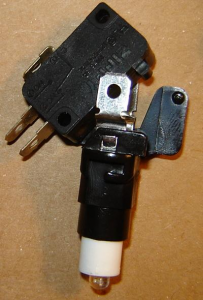
One stirrup connects to the LED anode, the other to the LED cathode.
You can test which is which using the diode setting on your multimeter.
(LED will light dimly when the red lead is on the anode and the black lead is on the cathode)
You can pull the LED out of the socket and turn it 180 degrees if desired -- I always orient the LED so the cathode (-) is on the same side as the big black plastic tab that holds the microswitch.

Based on your pic:
Connect the red wire daisy chain to the anode (+) stirrup tabs for "common anode" configuration.
*** THE "RED WIRE" DAISY CHAIN NEEDS TO BE CONNECTED TO 5V (+), NOT GROUND. (-) ***Ideally, the + pin (black line) would be daisy chained to the anodes of the three LEDs connected to the orange, gray, and yellow wires.
The orange (blue channel), gray (green channel) and yellow (red channel) wires go to the cathode (-) stirrup tab of three LEDs.
- Orange wire LED will light when RGB pins 49-51 are set to "blue".
- Gray wire LED will light when RGB pins 49-51 are set to "green".
- Yellow wire LED will light when RGB pins 49-51 are set to "red".
- Orange and yellow wire LEDs will both light when RGB pins 49-51 are set to "purple". (red and blue)
The Ultimate I/O lights the LEDs by applying ground to the R/G/B pins and turns them off by applying 5v to the pins.
It works like a spring-loaded, one-way plumbing valve.
If the voltage (water pressure) difference between the anode and cathode is enough to cause the LED (valve) to "forward bias", current will flow (water flows through the valve) and the LED will light.
If you install the LED (valve) backward, the voltage (water pressure) will "reverse bias" the LED. (push the valve closed)
Scott


 Home
Home Help
Help Search
 Login
Login Register

 Send this topic
 Print
Print Topic: how to wire single color leds on ipac ultimate (Read 9648 times)


