So, I did some more work last night. I'll try a new post method and do a talk for each picture that is attached.
-- 1 --
The easy part last night was sanding down one of the top pieces for the cabinet. It had a 30 degree angle in it so I had to do a sort of biscuit style attaching of two plywood pieces. The glue was all dried so I sanded everything smooth. This assembly will attach to the bottom of the marquee with the small section being the part that holds the marquee in place. The small piece will be parallel with the ground and the larger piece will then slant upwards towards the top back corner of the cabinet. The area that is created will provide room for a cavity that will house the speakers behind a speaker grill. To get a better idea see the sketch of the cabinet in the original drawing.
-- 2 --
This picture shows the door and the holes that had to be drilled for the hinges. I first did a test in a small scrap piece, also pictured, in order to determine how far away from the edge to drill the hole and to determine how deep the hole had to be. I ended up making the hole about 1/8" from the door edge while the instructions said 1/4". the hole I made is slightly oversize so I could move the assembly around if needed to closer mimic the location stated by the hinge directions.
-- 3 --
I did a test with the button centers 1-3/8" away from eachother to determine if that was acceptable. The result was that 1-3/8" is the minimum. Those buttons are Happ buttons by the way. Any closer and they would not fit properly. Some of my buttons are 1-3/8" apart but not all. If I made an error drilling, I will just widen the holes slightly but I think it is a non issue.
-- 4 --
The CP button and joystick layouts were laid out and taped down. In the end, the layout is fairly similar to what I had intended. The left joystick is 5-1/4" from the left edge. More than what others do, but I wanted it this way. In messing around with that joystick placement, I determined that 4-1/2" was the minimum so I was probably going to do that, so I did not feel bad about adding an extra 3/4".
-- 5 --
Using the paper templates, I used a small drill bit (something between 1/8" and 1/4") to carefully "dent" the acrylic with a hand drill wherever a button was to go. These acted as a pilot hole ("dent) for drilling the 1-1/8" hole for the buttons.
Each joystick center was drilled with the same drill bit (again, something between 1/8" and 1/4") all the way through to mark the joystick center in the acrylic and the wood. These locations were then used to cut holes for the u360s in the wood and to use the router to create the inset for the u360s to rest in for the surface mount. When determining the inset depth, I also took into account the fact that a screw head would be on top to hold things in place.
Image 5 is there to show the dents that were formed in the acrylic.
-- 6, 7 --
These two images show the CPl top resting on top of the CP box. Yes, 9 buttons. I spent the extra $10 on something that might not be needed. I used a button/joystick template from slagcoin referred to as the "Sega layout" and added a thumb button to it. I located the thumb button at approximately a 45 degree angle to the bottom left button and located it 1-1/2" away.
http://www.slagcoin.com/joystick/layout.html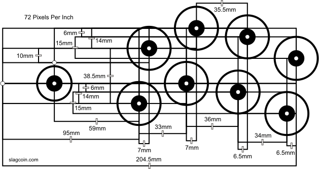
I used the alternative joystick center that is the small circle on the left edge of the image.
No one told me how long the CP top would take

I think I spent about 4 hours doing the holes/routing in the CP top.


 Home
Home Help
Help Search
 Login
Login Register

 Send this topic
 Print
Print Topic: Gamesomnia - inspired by Knievel's Woody Cab (Read 26670 times)


