Here is the my journey of countless hours and sweat to make the coolest super emulater cabinet I could. The cabinet is pretty much done. You have no idea how many hours you are going to put in to a project like this. I hope you enjoy!
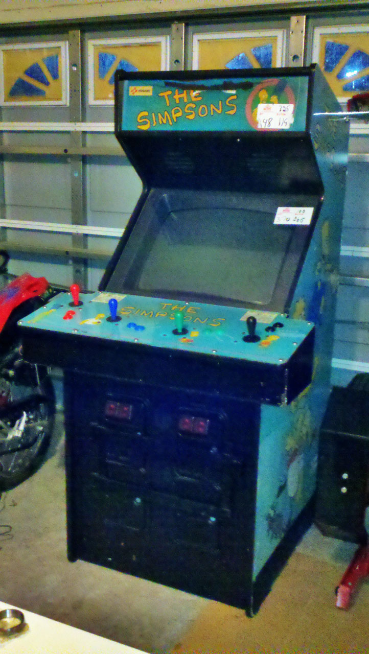
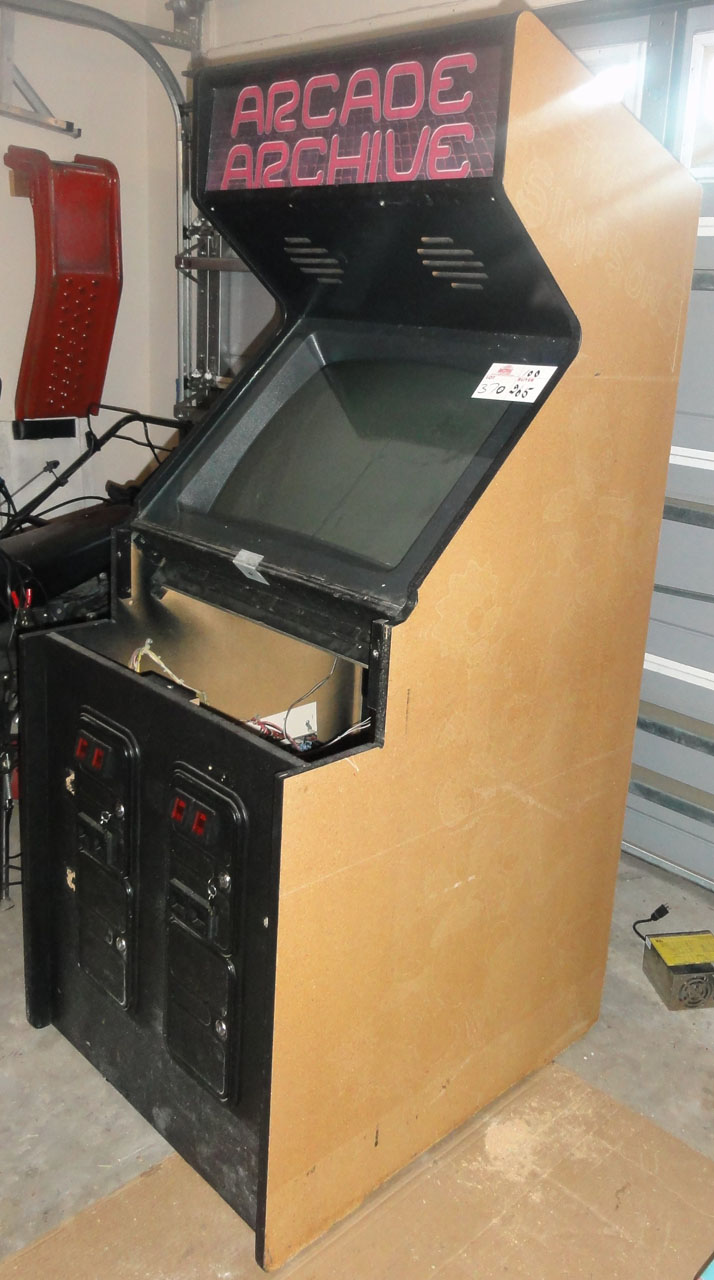
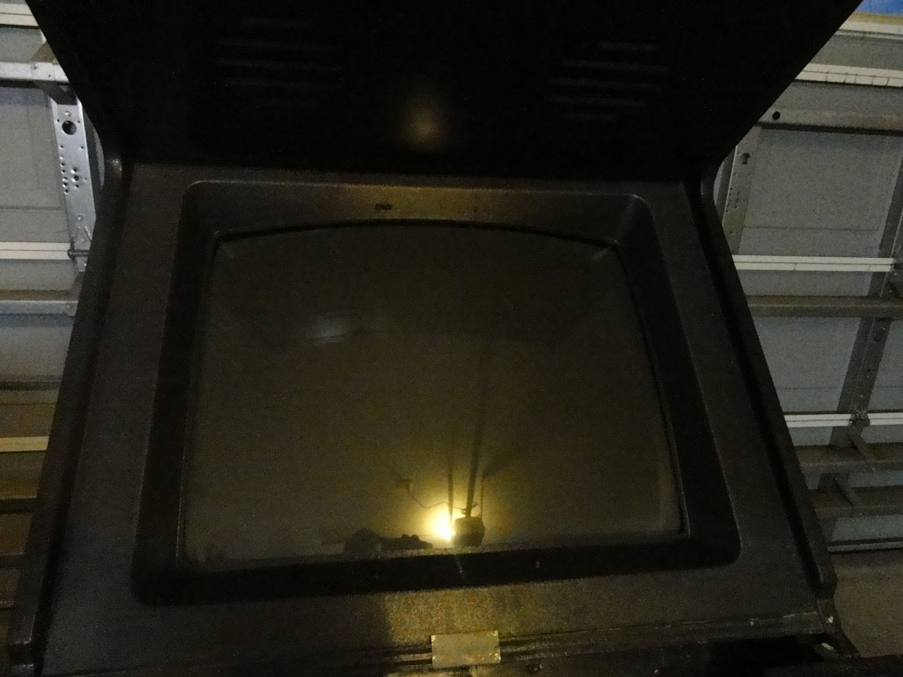
Here is the Simpson's cabinet I bought at an Auction
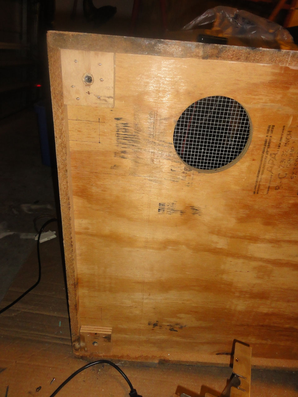
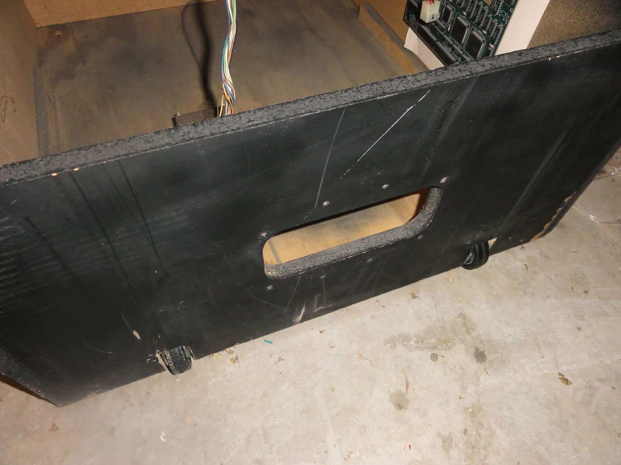
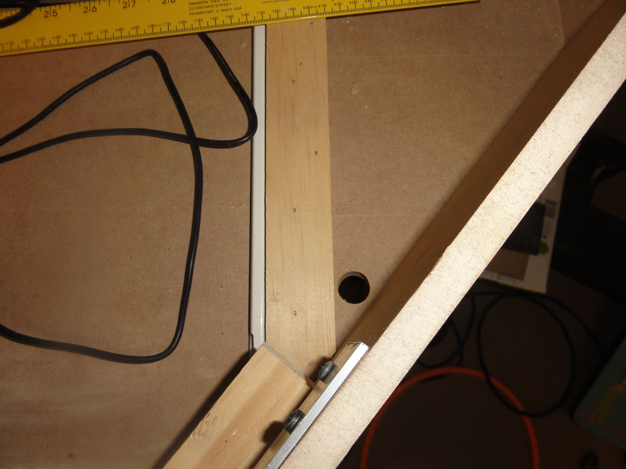
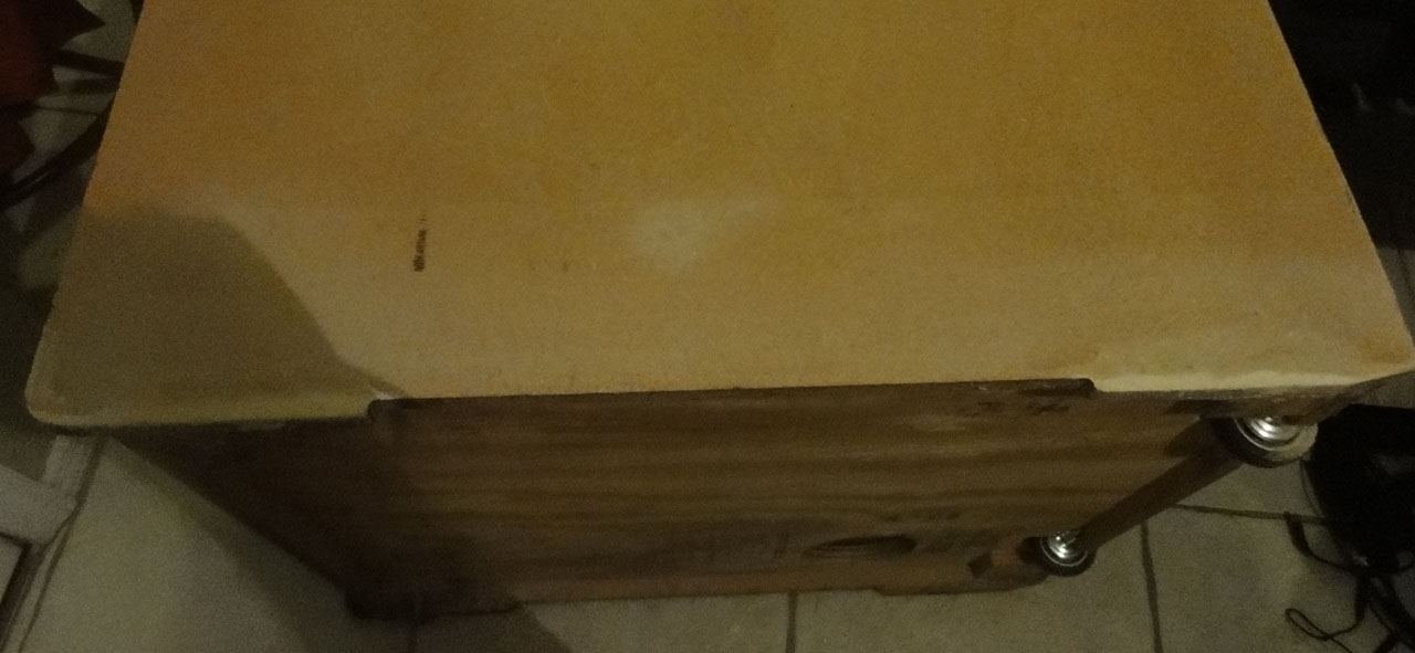
First I wanted to add some wheels to make it easier to move around. The lines are where I need to cut to add the wheels.
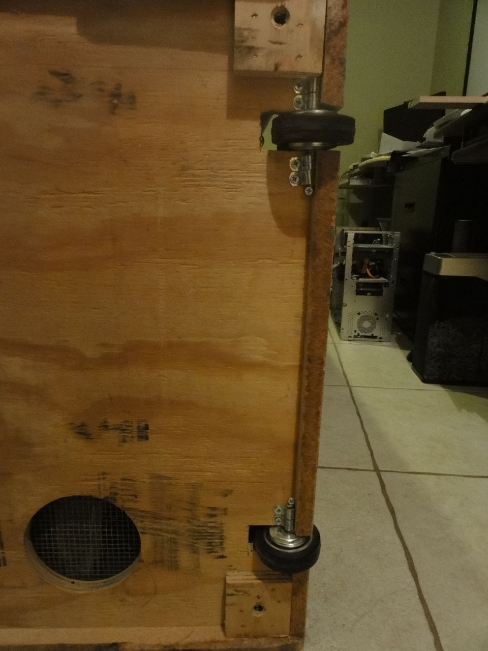
I Cut 2 pieces of metal of a U bolt to be the axles and used some metal clamps to hold the axles to the cabinet.
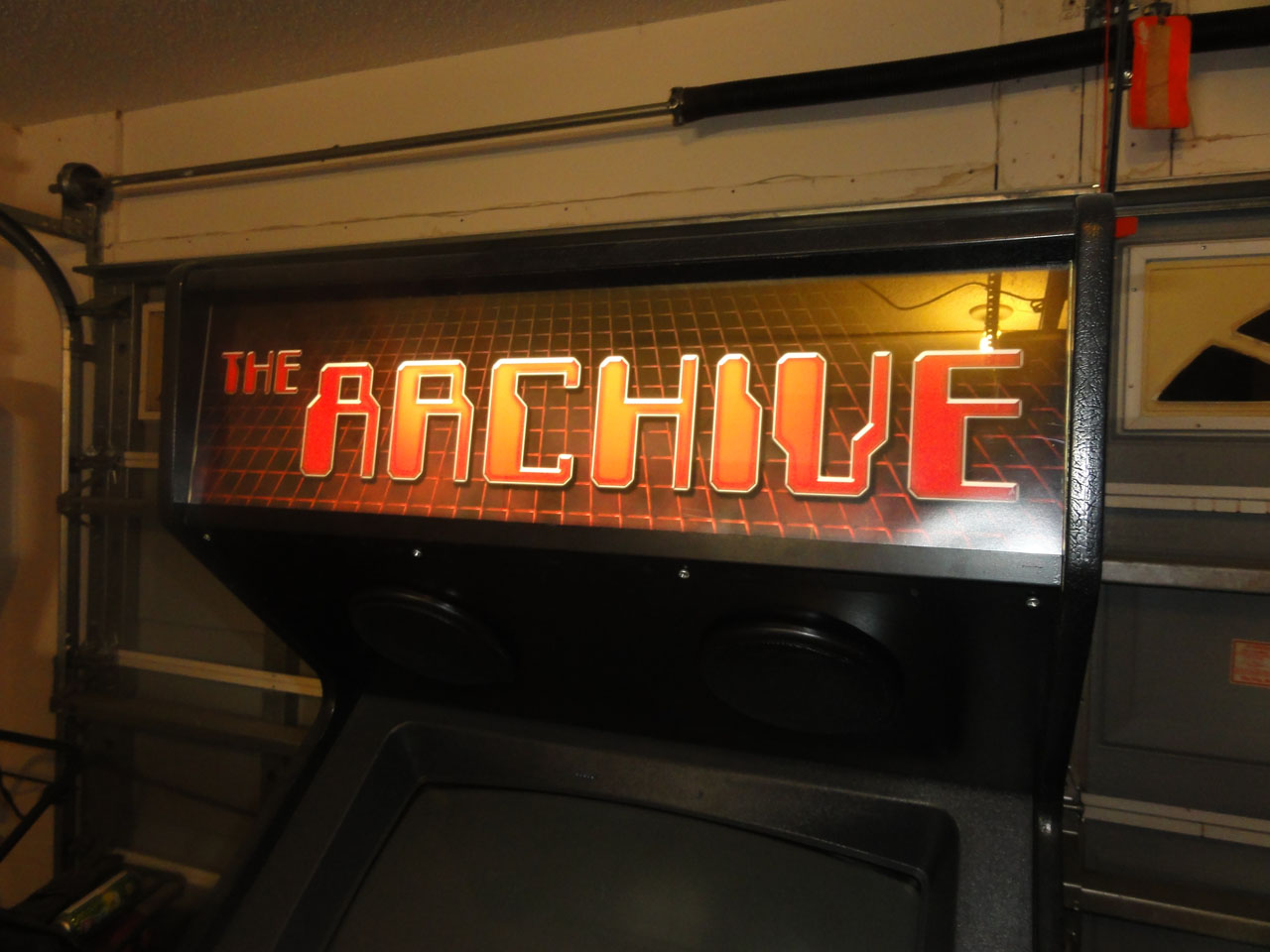
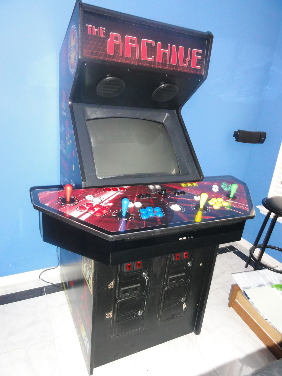
I used a Heat Gun I got for cheap at harbor freight (Love that place!) and pealed off all the Simpson's art work. The Marquee is just temp crap I printed off on my inkjet.
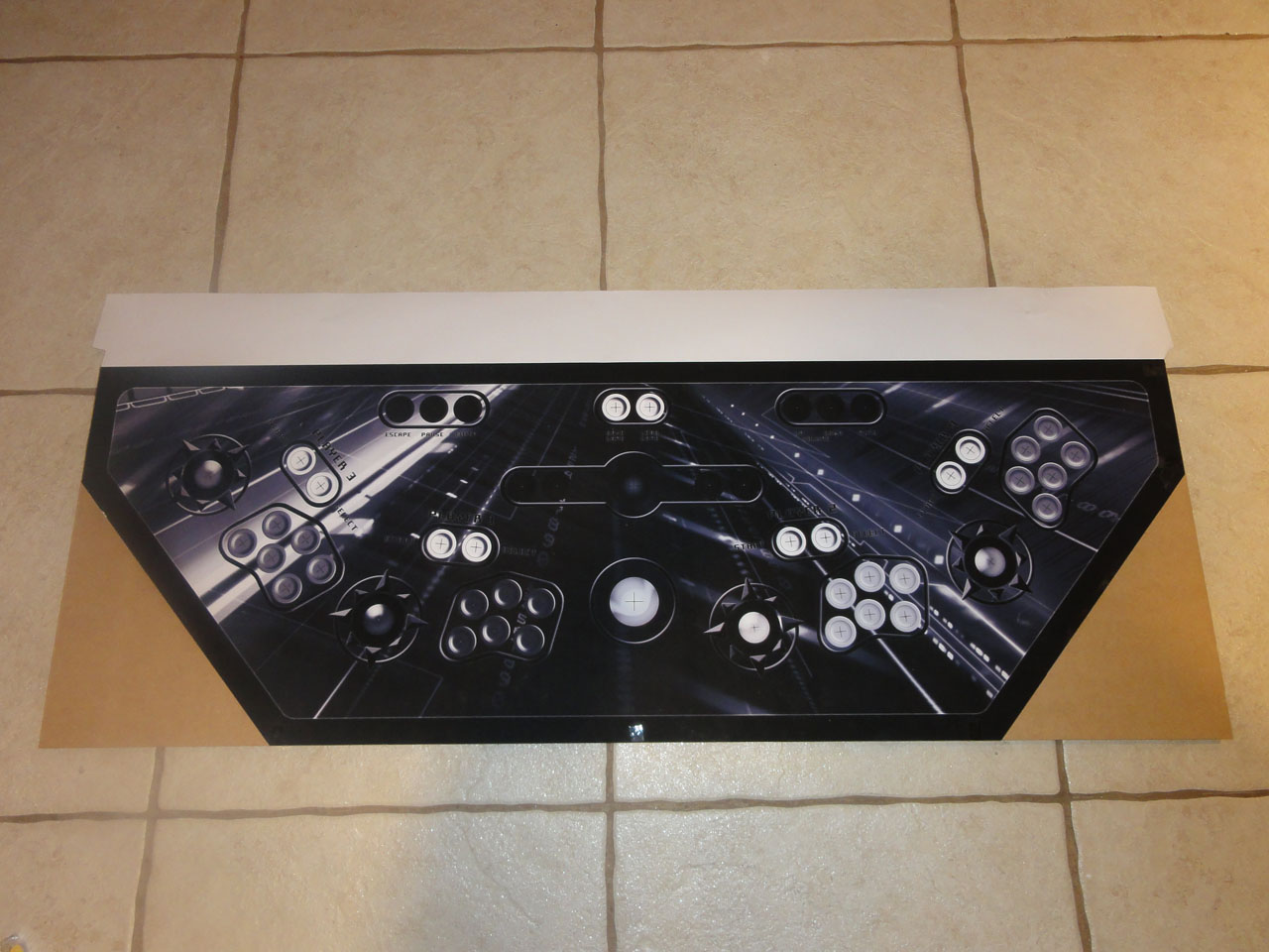
So...so...many hours went into designing this control panel from scratch in Photoshop. The actual file is 300 DPI and has many layers. It ate up all 4GB of Ram a few times while working on it. Before designing it, I created a template with poster board to figure out just what angles I wanted to place each player at.

Here is a Black and white template I used for marking all the holes and angles to cut in the 3/4 MDF for the Control Panel. I got the template printed at Office Depot for under $8!
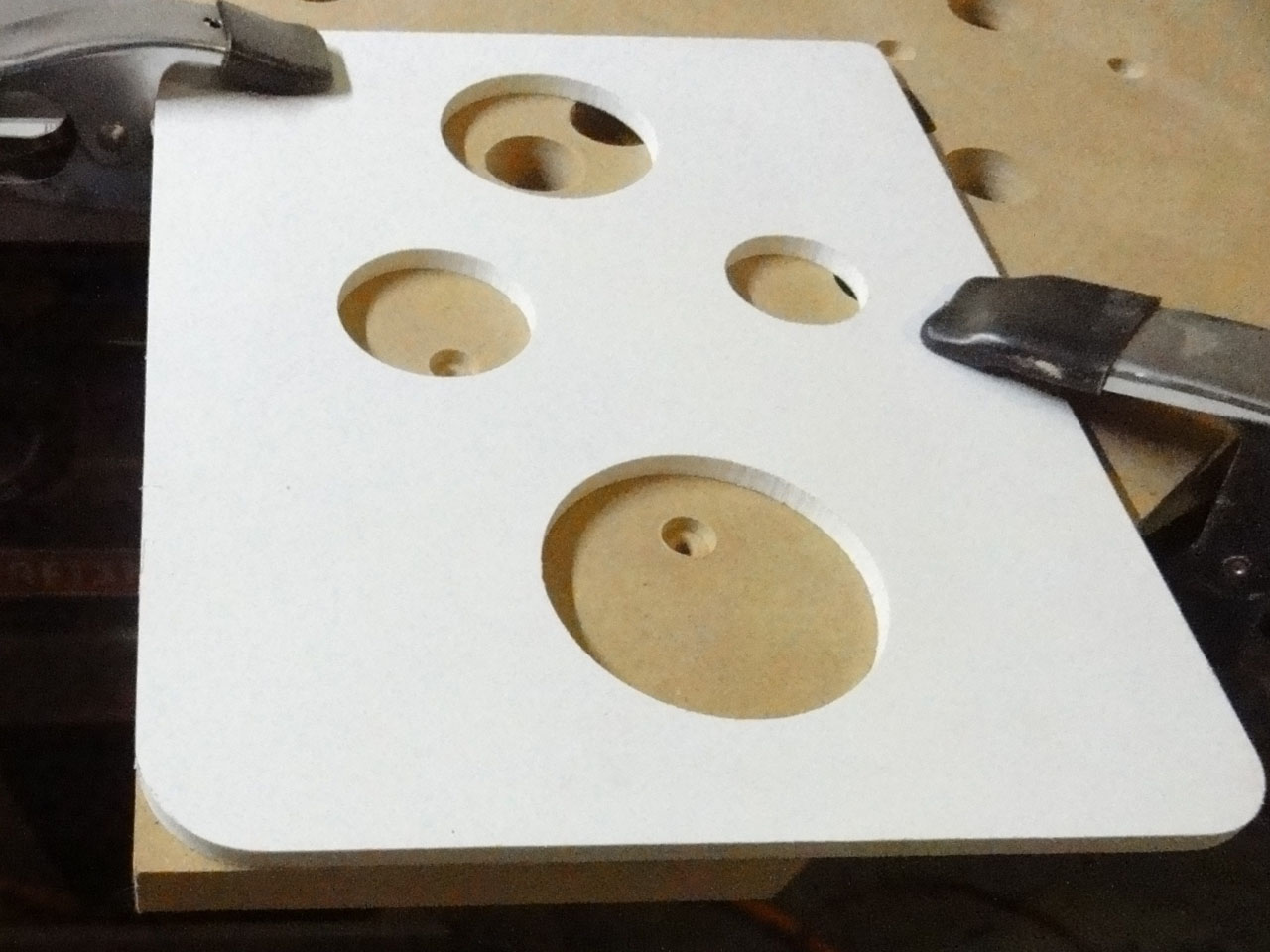
I used a 1 1/8 forstner bit I got at Lowes to cut the button and joystick holes in the MDF. I would definitely recommend it over the spade bit unless you have a large drill press. I also drilled the bolt holes for the joystick with a standard bit. But used a larger bit to make drill enough wood away so that the bolts would be beneath the plexiglass and artwork. With all the holes cut in the MDF I took 1/16 plexiglass and drilled starter holes with a spade bit. Then used a Flush trim bit on my router to finish the holes in the plexi. I was SOOO nervous about cutting the plexi, but with the router it was too easy.
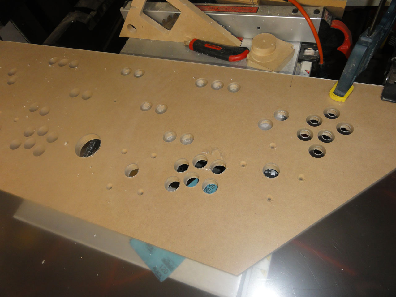
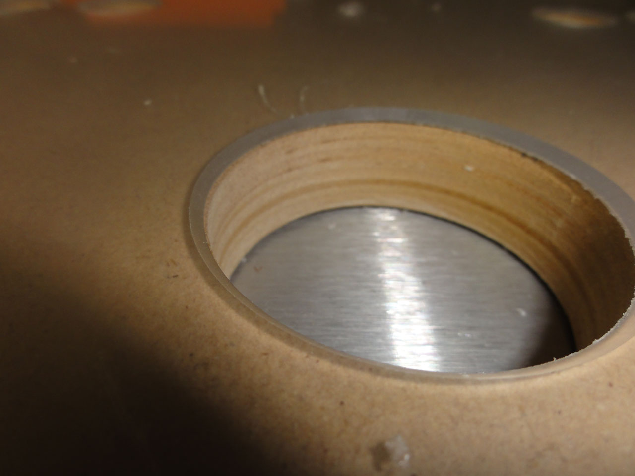
For the Track ball hole I finished it off with a chamfer bit in the router to create a 45 degree bevel.
Here is where I cut out the hole for the trackball and routed away material for the joysticks & spinner. I dont know if I need to do it for the joysticks, but I definitely needed to do it for the tempest like spinner I picked up on eBay.
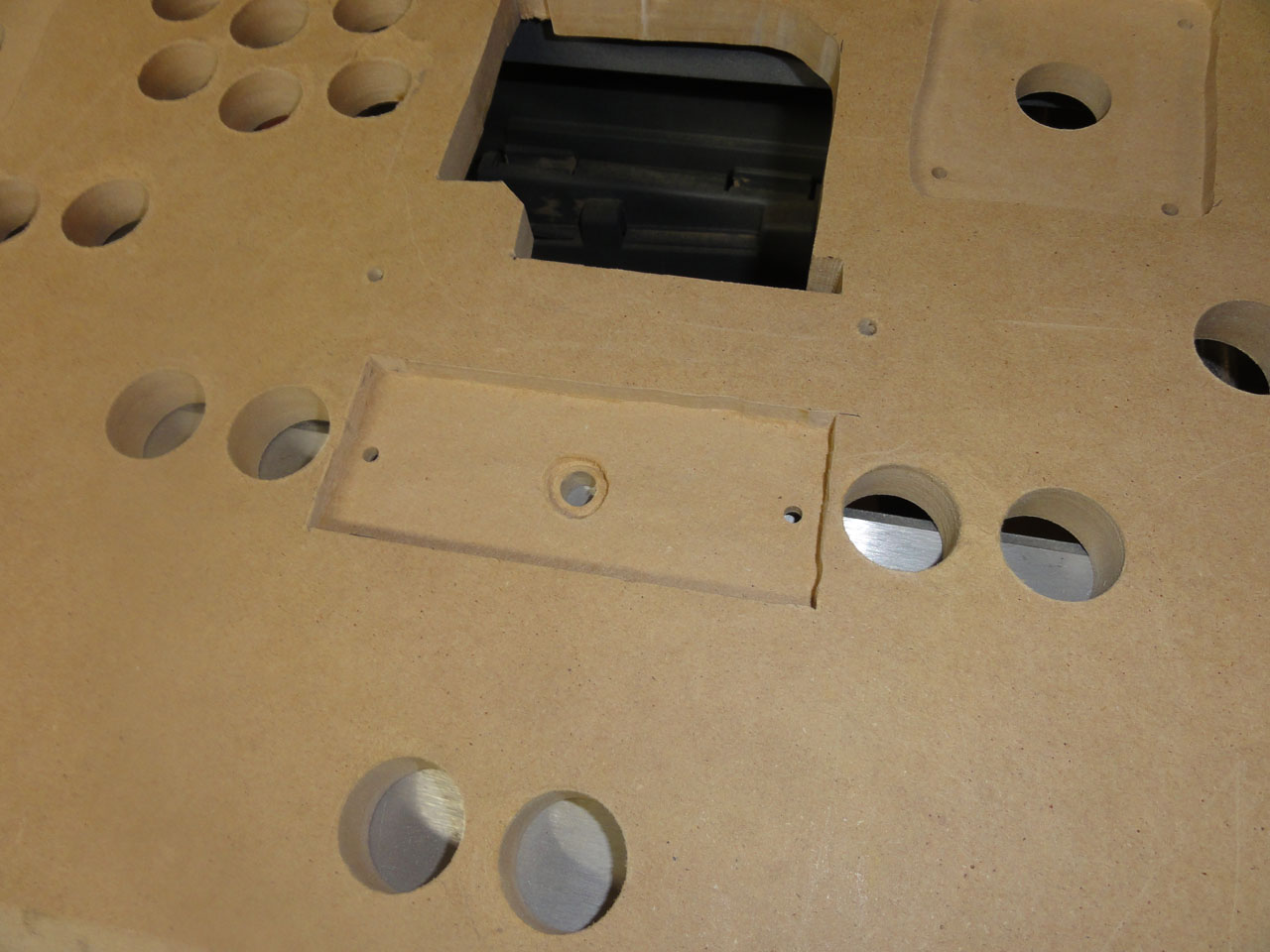
I routed more wood away so that the trackball mounting plate would sit under the artwork as well.
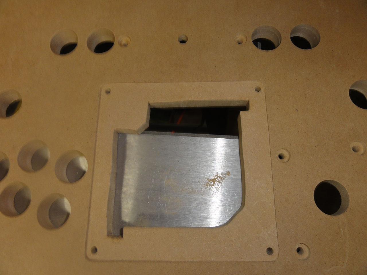
The track ball mounting plate for the 2 1/2 inch track ball. I would of preferred to get the bigger trackball, but I got this one on a special deal. It actually would not sit in the mounting plate flush. I had to use my Dremel to grind some paint and metal away from the hole so the track ball would sit properly.
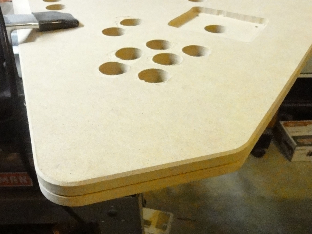
I got this router template from
http://www.routertemplate.net/ because I knew there was no way in hell I was going to be able to free hand a curve and not mess it up.
I beveled the bottom edge of the CP because I wanted the t-molding to sit flush with the plexiglass top. However in some really bad luck when I cut the slot for the t-molding the router did not cut at the same height that I just spent 8 tests tries to get just perfect. I am still baffled by why it did not cut right. Boy did that really make me mad. Since I was not going to redo everything, I put a 45 degree bevel on the plexiglass edge instead.
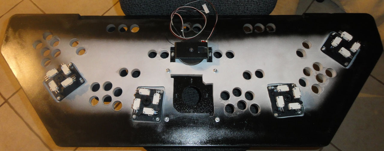
The bottom of the control panel primed and painted, with joysticks bases, trackball mounting plate, and spinner attached.
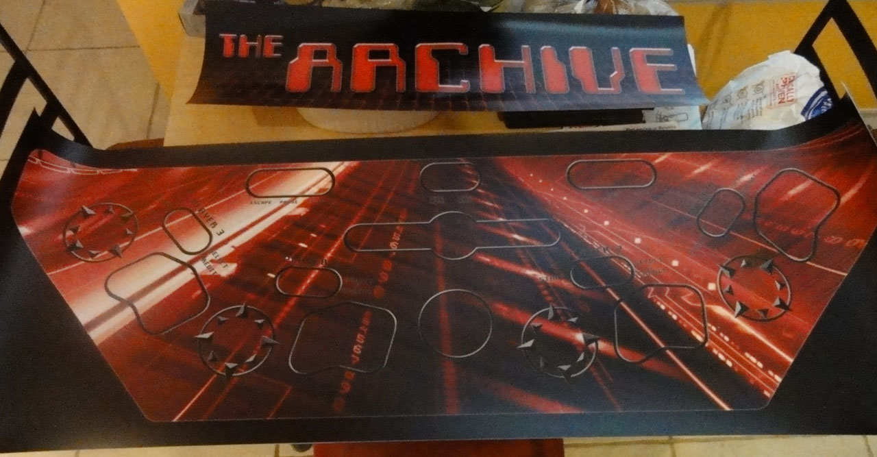
My artwork from
http://www.gameongrafix.com/ I have to say they did an outstanding job on the printing. The Marquee and CPO were perfect.
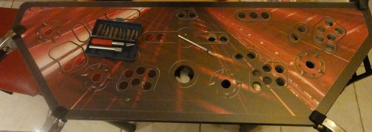
Cutting the CPO to size
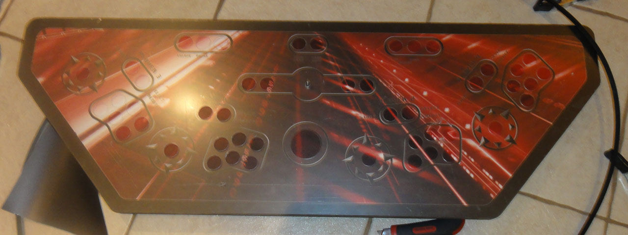
Using a pen knife and the plexi + MDF as guides to cut out all the holes.
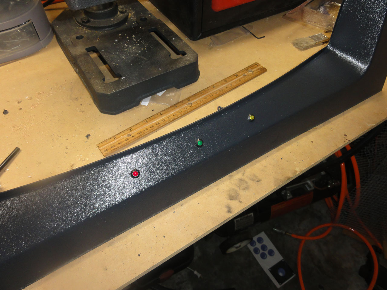
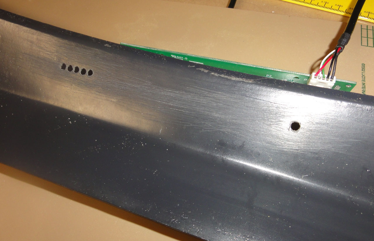
I cut three holes into the monitor bezel to mount the LED lights that feed from the IPac4 I got from Ultimarc.
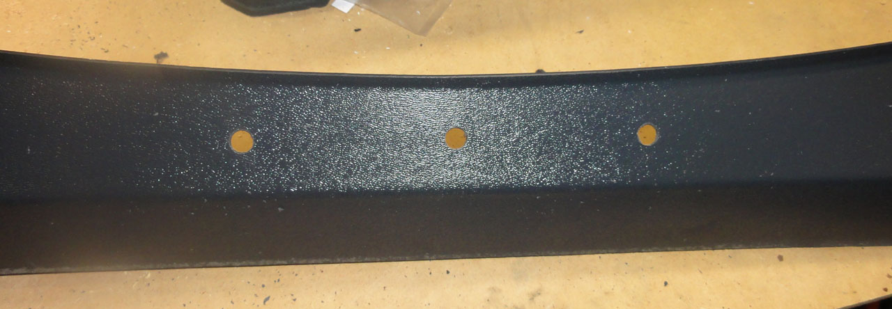
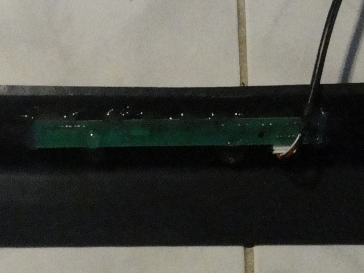
The Leds mounted
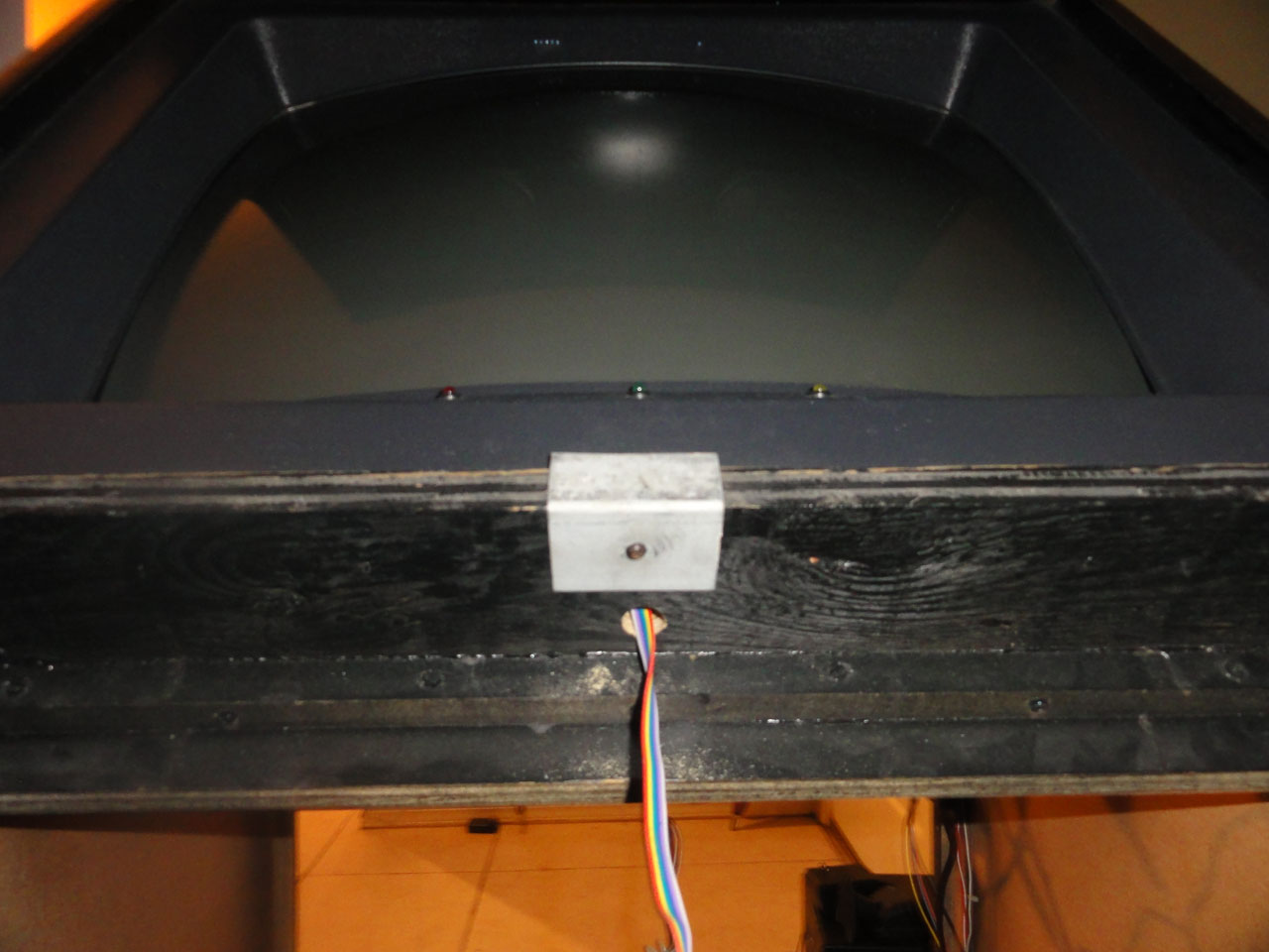
Drilled a hole for the wires from the LEDs to reach the IPAC4.
In the top of the bezel I drilled holes for the AIMTrak leds for the 2 light guns I will have. More on them later.
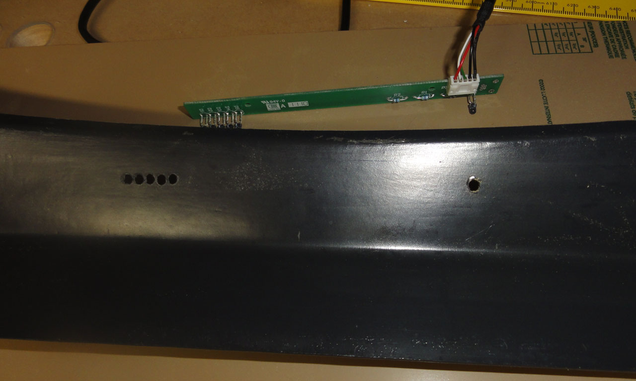
The template I created for drilling the holes.

I scratched up the plastic on the inside of the bezel, hopefully to help the hot glue hold better.
The hot glue holding the AimTrak LED board in place.
The finished product.
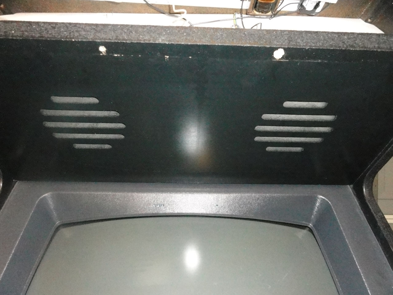
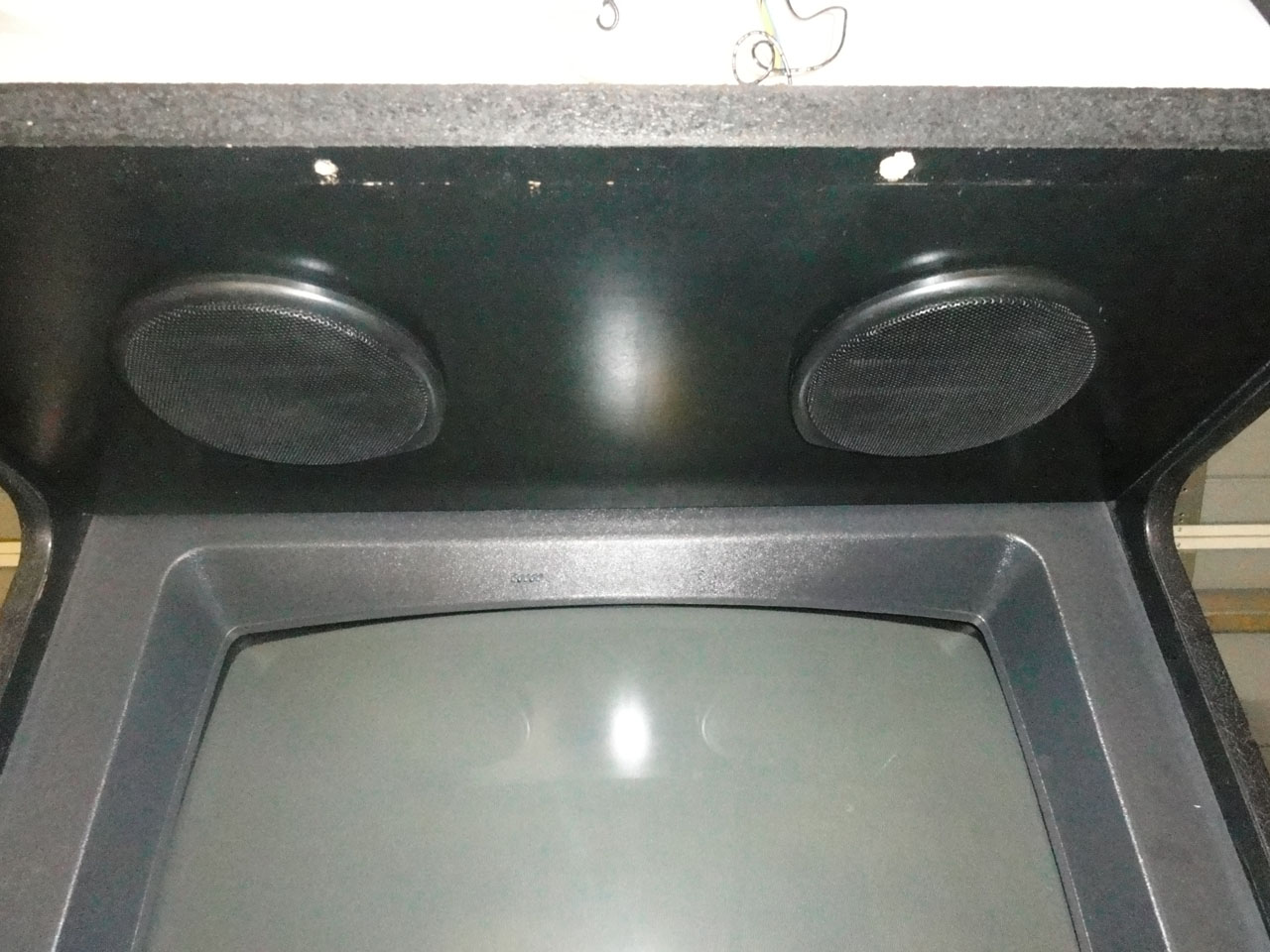
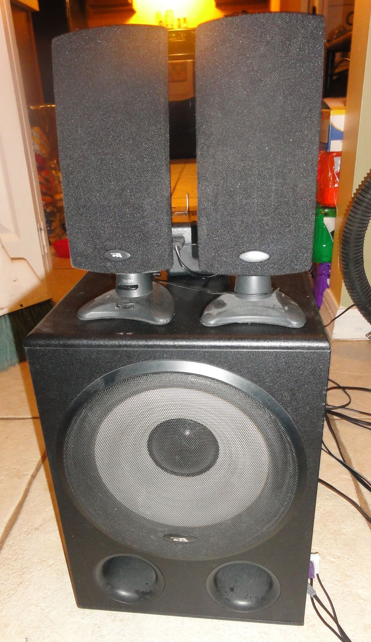
I did not like the speaker holes so I got some cheap grills on ebay to spruce them up.
The Marquee sandwiched between 2 pieces of plexi. I cut a piece of MDF to the size of the Marquee and then used it and my router with flush trim bit to cut the plexi.
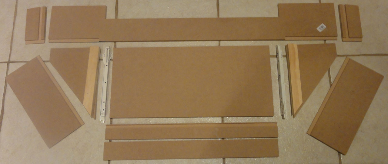
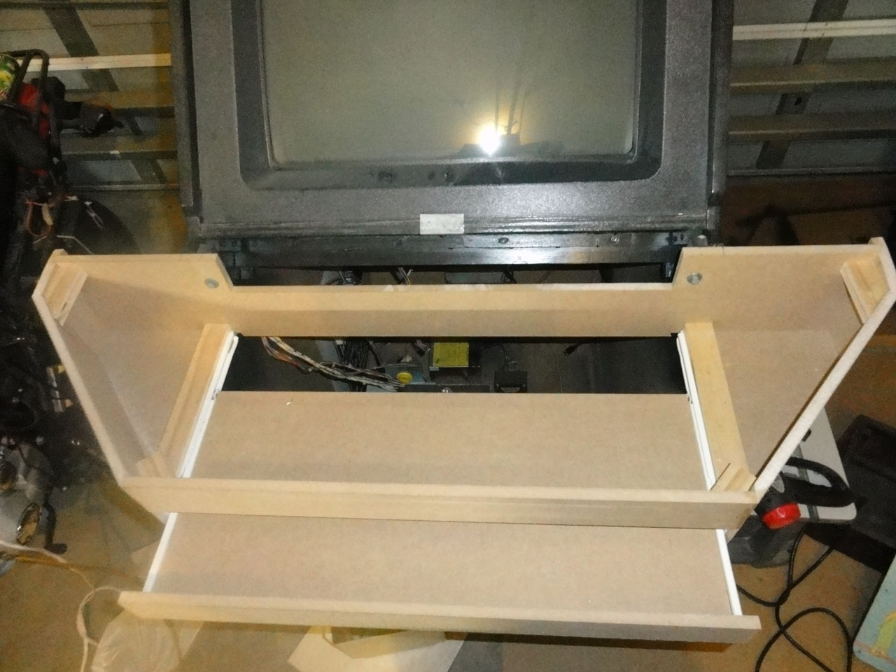
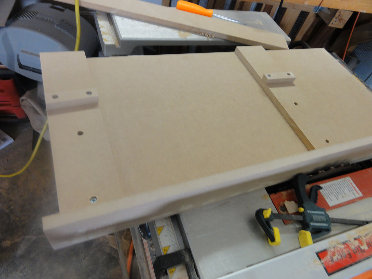
The pieces cut for my base. This was self designed as well and since I wanted a slide out keyboard and mouse, it took me a lot of thought on how I would do it. Even after this pic was taken I had to recut a few pieces due to stupid mistakes and things just not fitting the way I wanted them to.
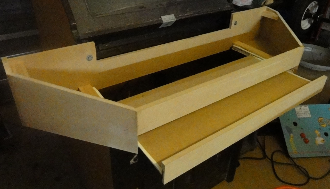
The base assembled with wood glue and a brad/nail gun.
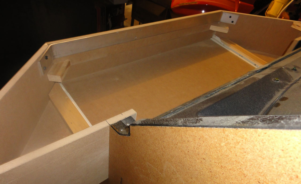
I was worried that the 1/2 MDF I build the base out of would not hold the weight of the control panel when it was lifted on its hinge. So I bent some scrap aluminum to provide extra support.
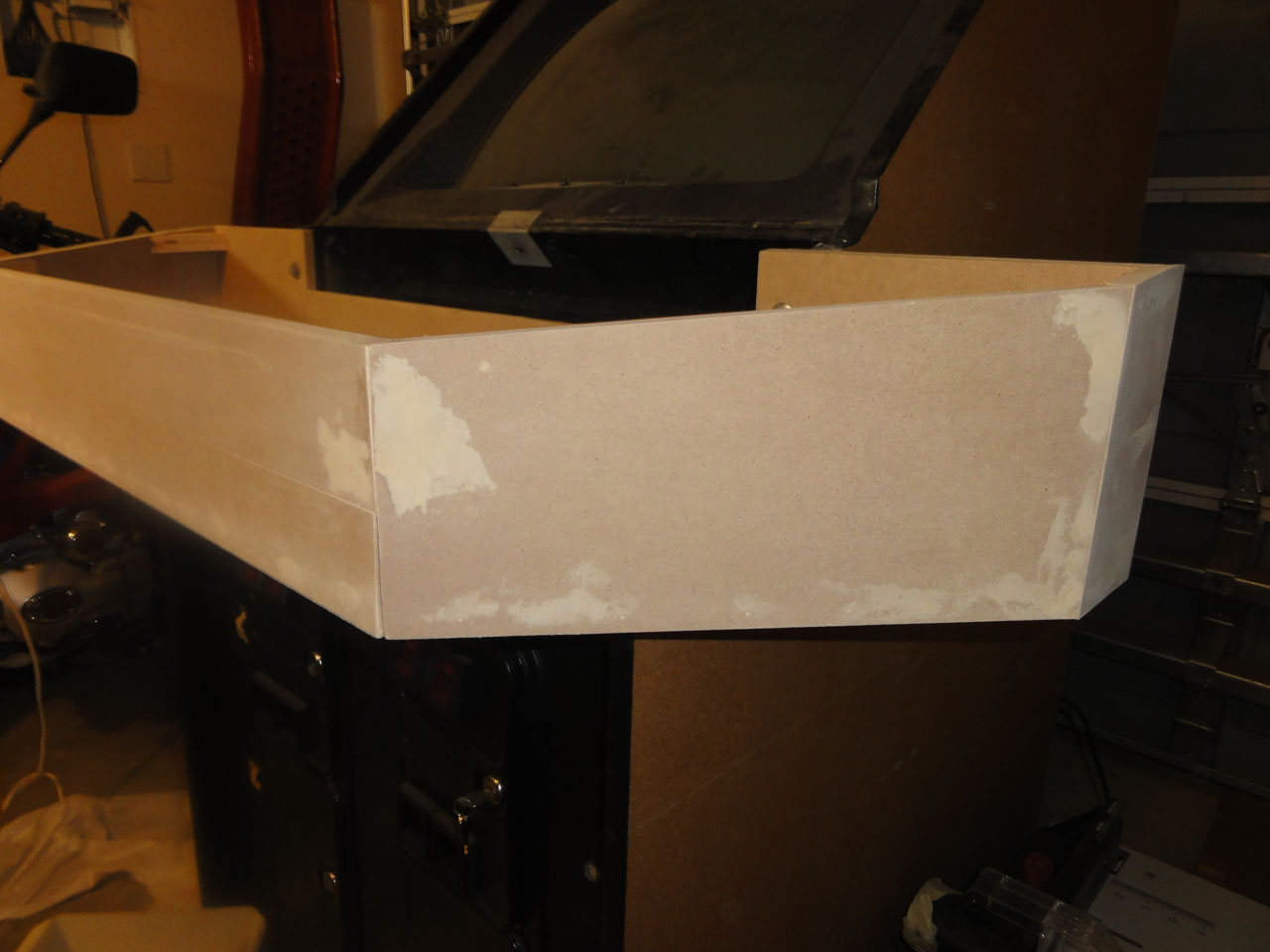
Finishing work with wood filler and sanding.
Drilled holes on both sides for USB wires comming from the guns.
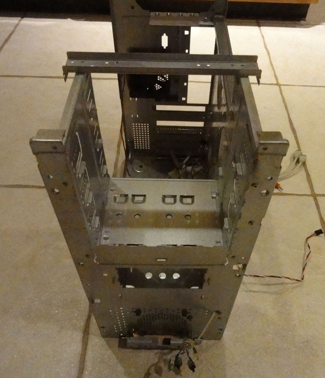
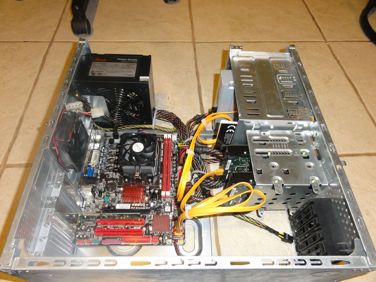
A computer case I had left over from an old PC. I striped it down to what I needed. I could not design it any more perfect.
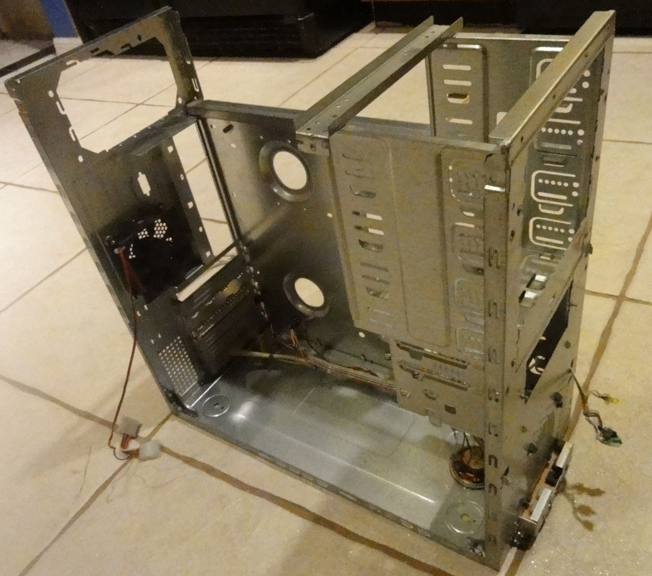
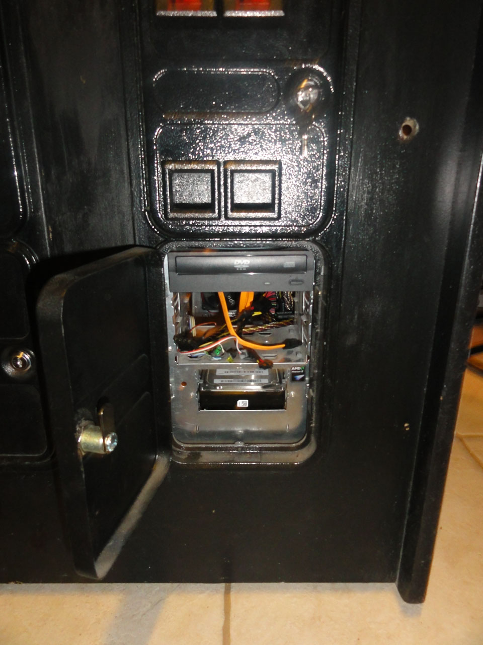
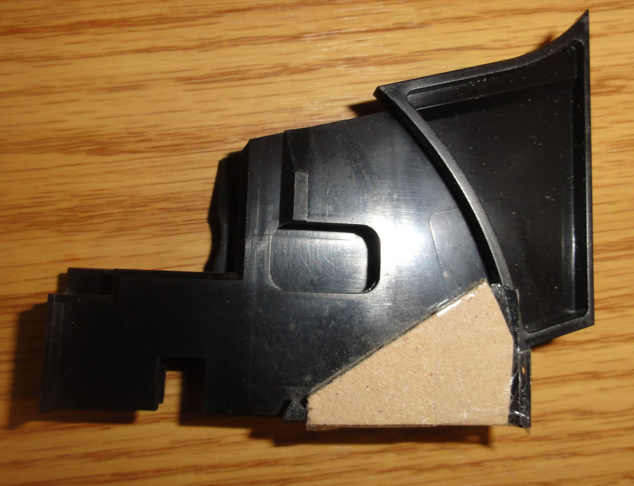
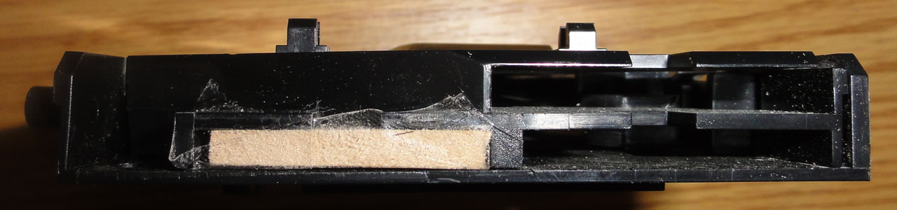
I want it to sit so that DVD drive is right behind the second coin collector door, so I had to cut away the top part so it did not infringe on the coin mechs.
I realized I could unscrew the mount for 2 usb and a line in and line out jack off my old case. Hmm where can I put it!
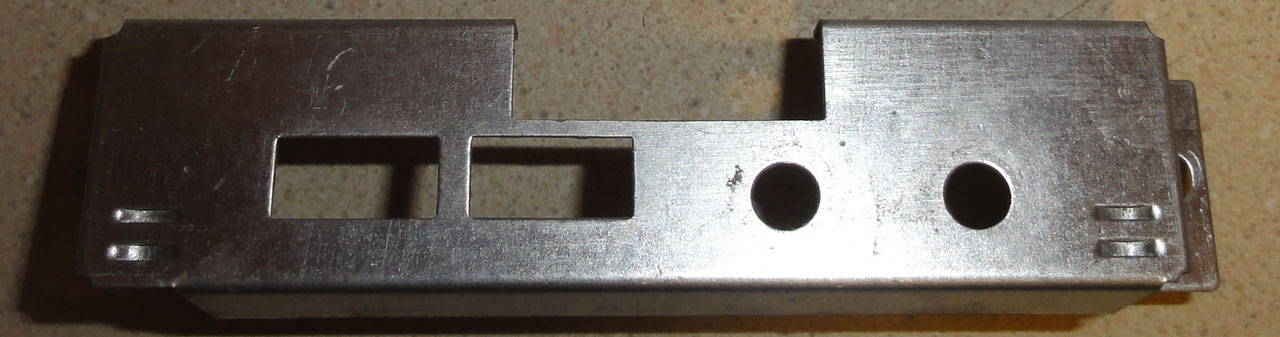
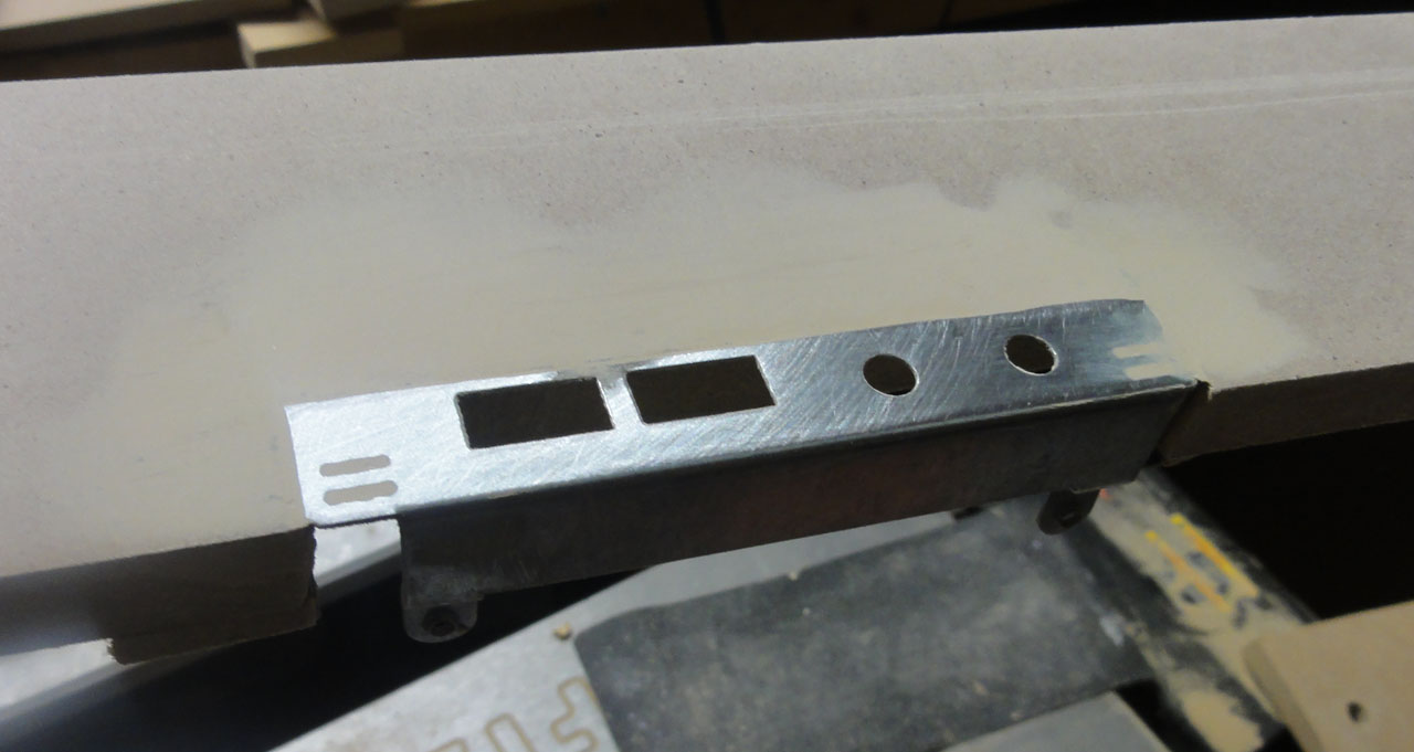
Cut away some of the uneeded metal
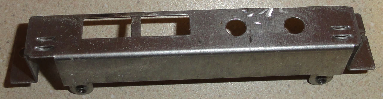
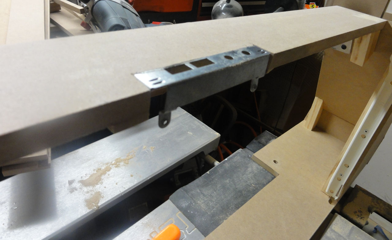
Looks like there was room for it in the base.
Finished off with wood filler, and sanding.
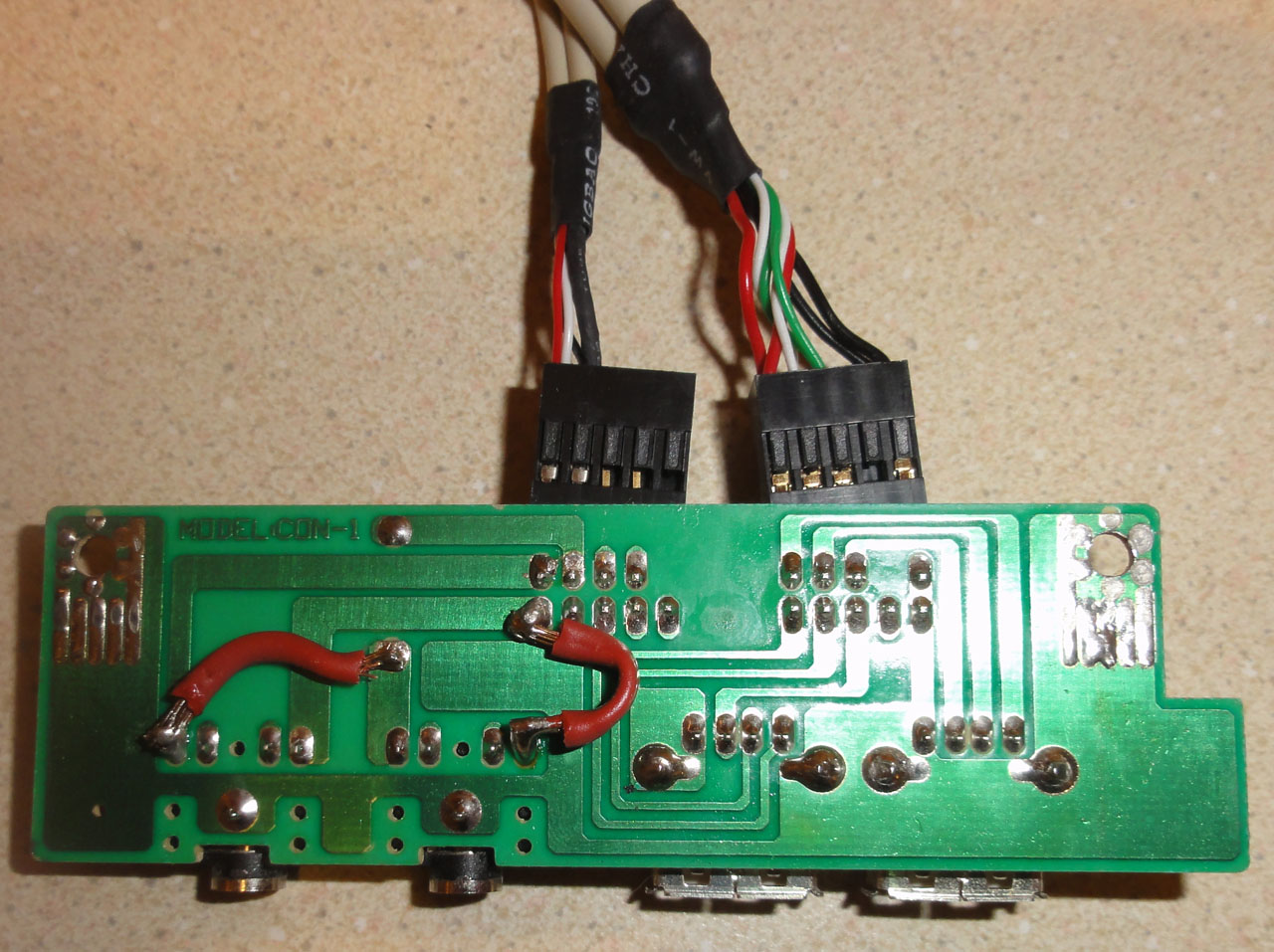
The board for the extra usb ports and line in and headphone jacks.
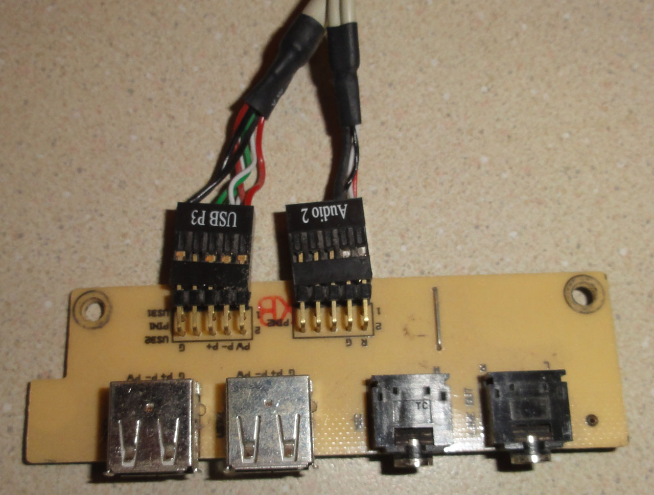
Since I did not need a line in jack. I cut the connection to the line in wire, and soldered the connection from the headphones jack. Now I have 2 headphone jacks!
Added some wood to raise the keyboard level and hold it in place.
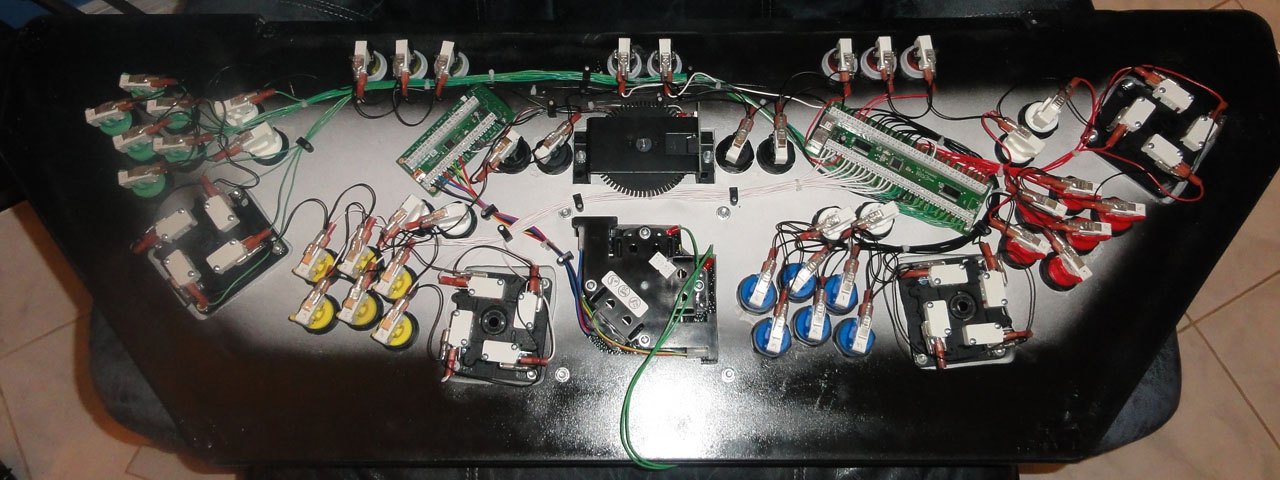
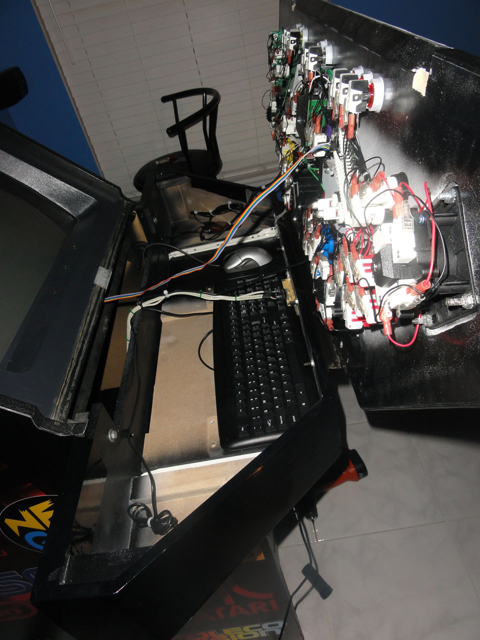
Button and joystick wiring done (or so I thought). I did not really plan for where I was going to put the IPac4 and the Opti-pac. So I was limited where they could go and in what direction. I tried to make it clean as possible considering. I found it was best and cheapest to buy security wire with 4 18gauge wire in it and strip off the outer sheath to get the wire for the buttons. I also had to mash the connectors at the very end so they held on to the microswitches tight enough.
Sanding and filling the bottom edges that had chips missing and a little water damage.
Before sticking my side art (also anouther amazing job done by
http://www.gameongrafix.com/) I colored the edges with a big fat black marker. This was so when I trimmed the site art no wood would peak trough at the very edges.
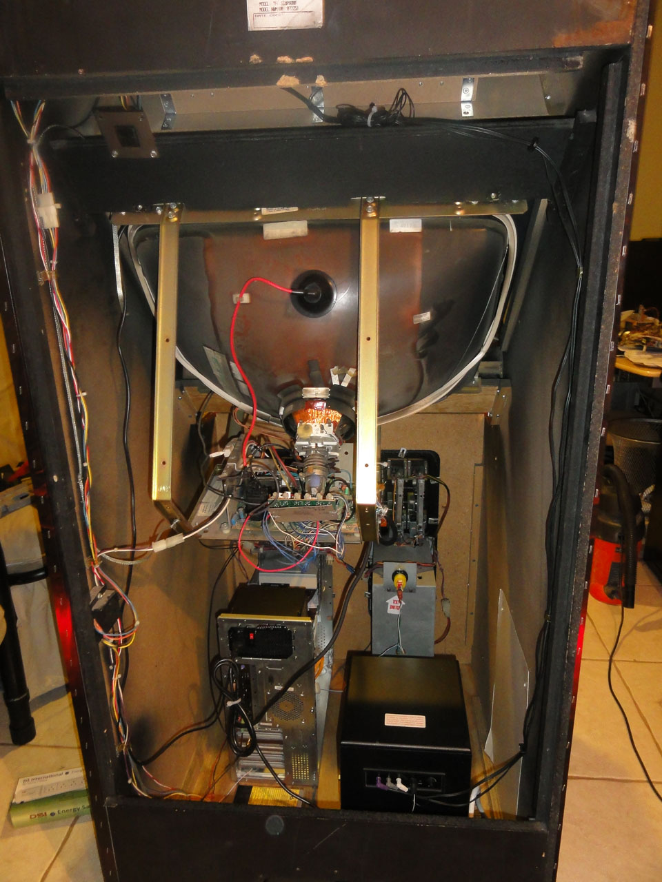
What it looked on the inside minus the power supplies and the one coin box I removed to make way for the computer.
The computer: (funny it is now the fastest computer in the house out of 5 others)
AMD Phenom II X4 925
2 GB of Kingston DDR3 Ram
2 2TB Hard drives (one for back up)
400 Watt Rosewill power supply
Biostar A8800G+ Motherboard with ATI Radeon HD 4250 on board
Rosewill Wireless N PCI card
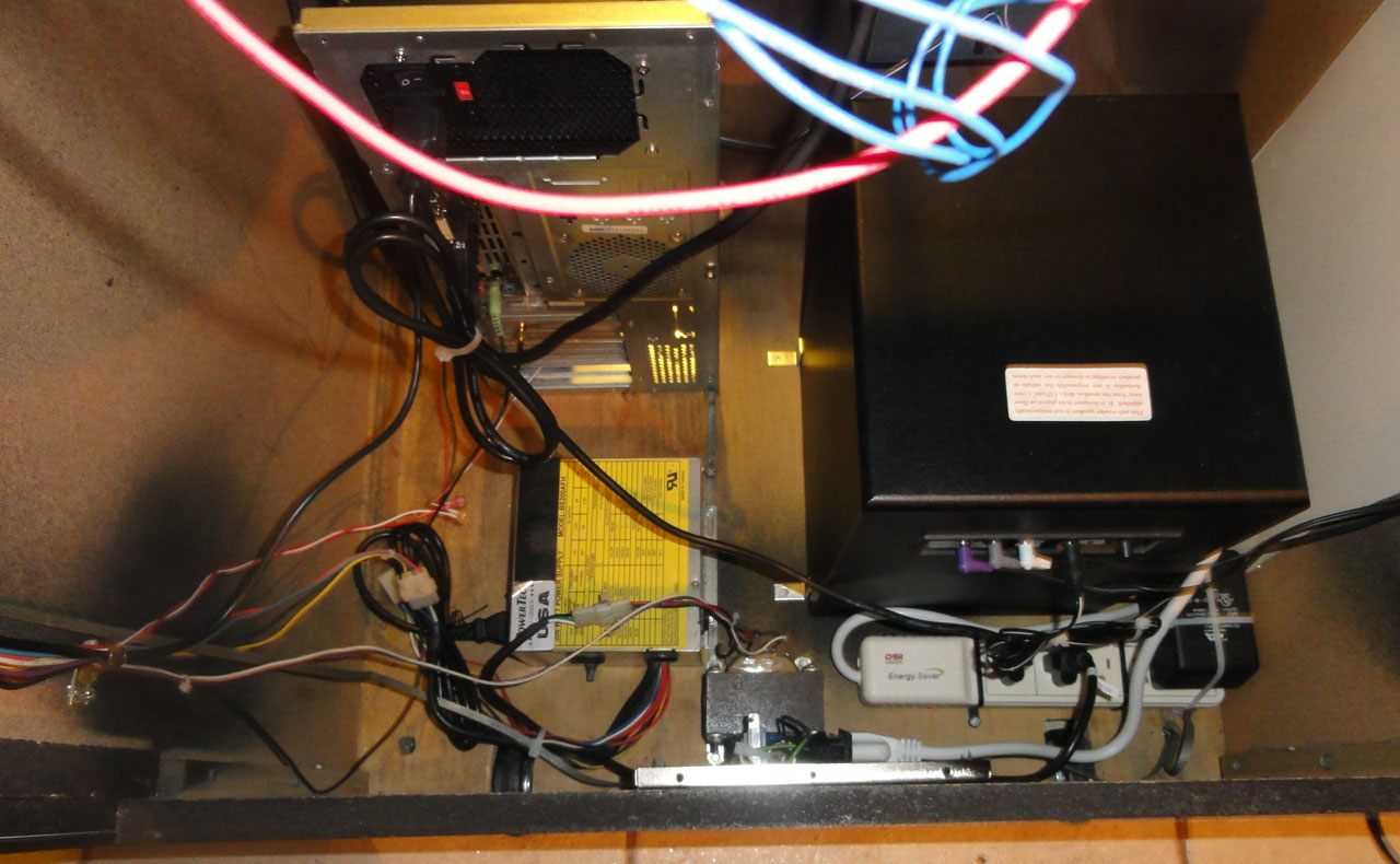
The computer mounted behind the bottom right coin door. The Cd tray comes in and out perfectly. I left wires so I could easily hook up a hard drive to easily copy files.
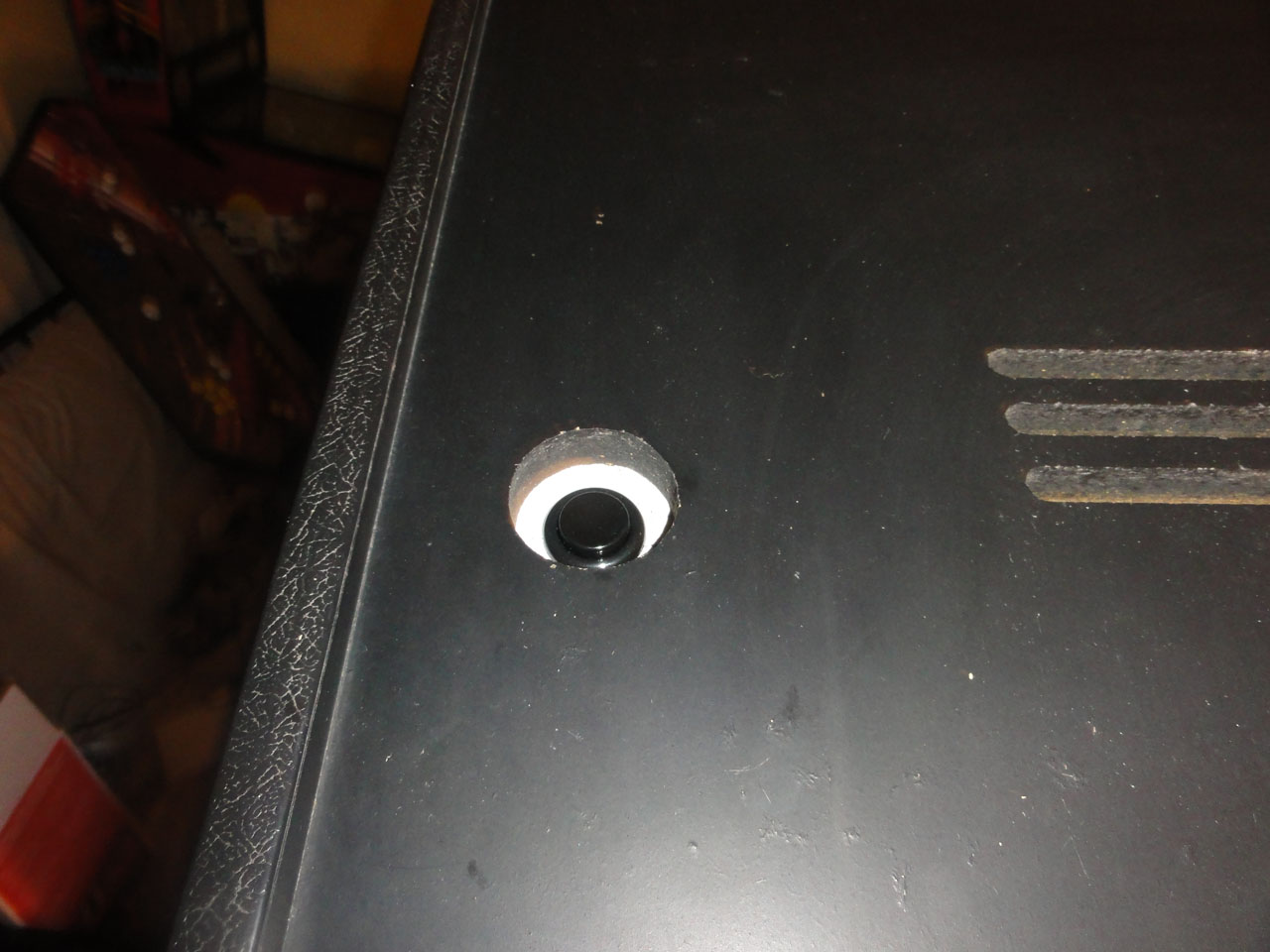
The computer mounted and the reset button wired to the old service button that is mounted on the right coinbox.
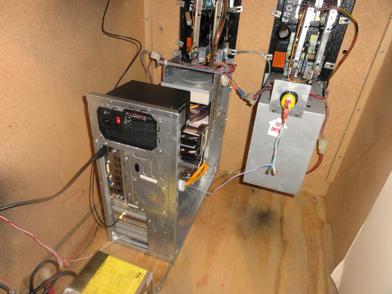
I wired the computer button to an arcade button on top where the old arcade power button used to be. I got a power supply that detects if the first thing that is plugged in (IE the computer) is on, it then turns the other sockets on. So when I press the button on the top, it turns on the computer, speakers, and arcade power supply (monitor, marquee light, and coin door lights).
I made some wood inserts to make sure all coins feed back out the coin return slot. I did not want coins falling on the computer.
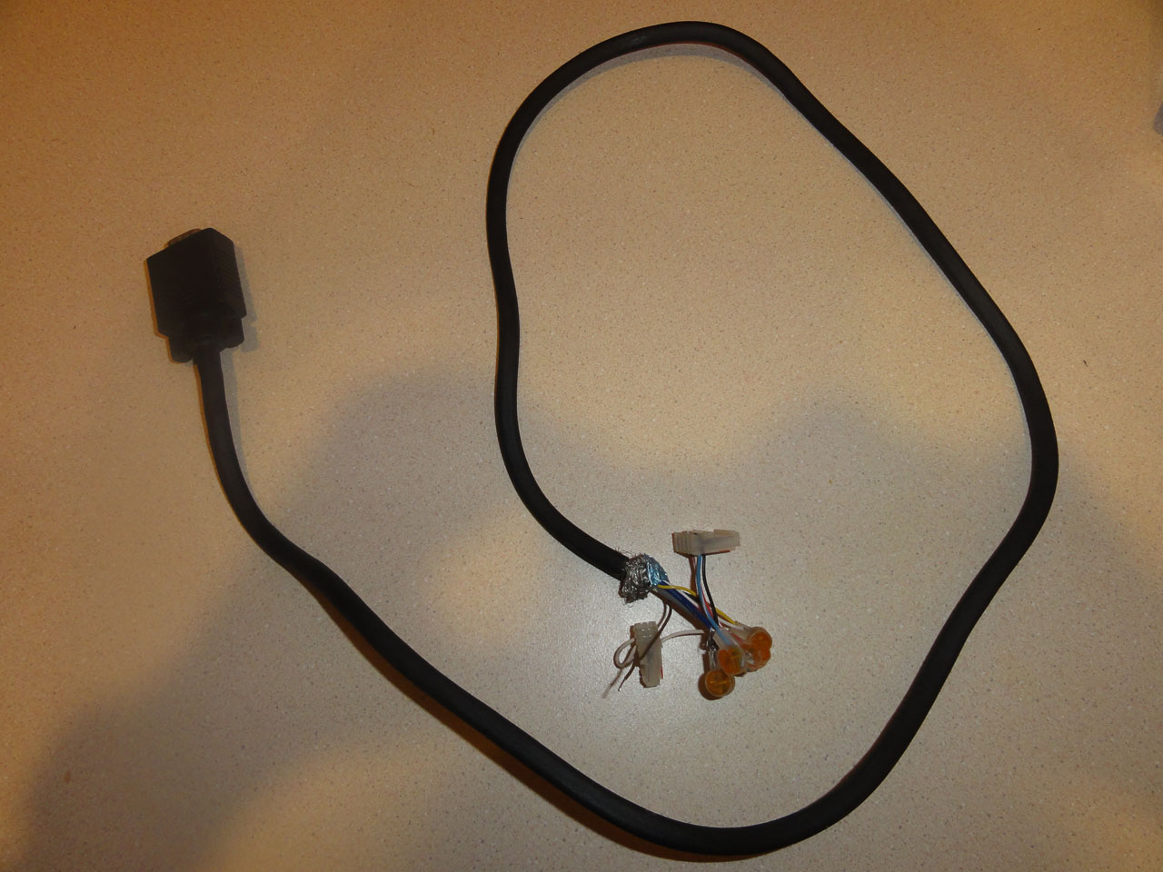
Home made VGA to arcade monitor cord. My arcade monitor can except 1 watt signals that the vga connector puts out as long as you turn the contrast up. I was lucky I did not need to buy a video amp. I am using Soft15k software and it works great with the onboard ATI Radeon HD 4250 except for the very first bios bootup screens.
The speakers and sub waiting to be mounted.
The little speaker shelf I built so the speakers would be right over the old speaker holes.
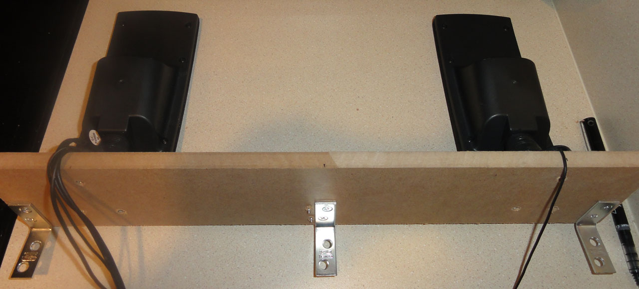
The speaker shelf mounted. You can also see where I put the old arcade power on switch (which can stay on all the time with the smart power strip I got).
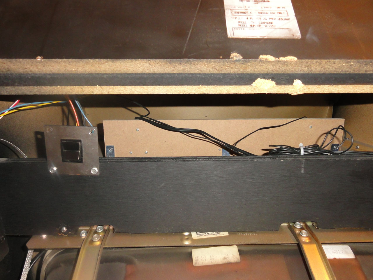
The subwoofer mounted with L-brackets, the smart power strip mounted with Zipties, and the second arcade power supply that in the machine.
It looked like the original power supply failed and the just spiced a new one on to the old one. I gutted the old one and cut the back metal plate from the rest of it. I then spray painted it and wired the female computer power connect to a standard male connector on the inside to plug the power strip into.
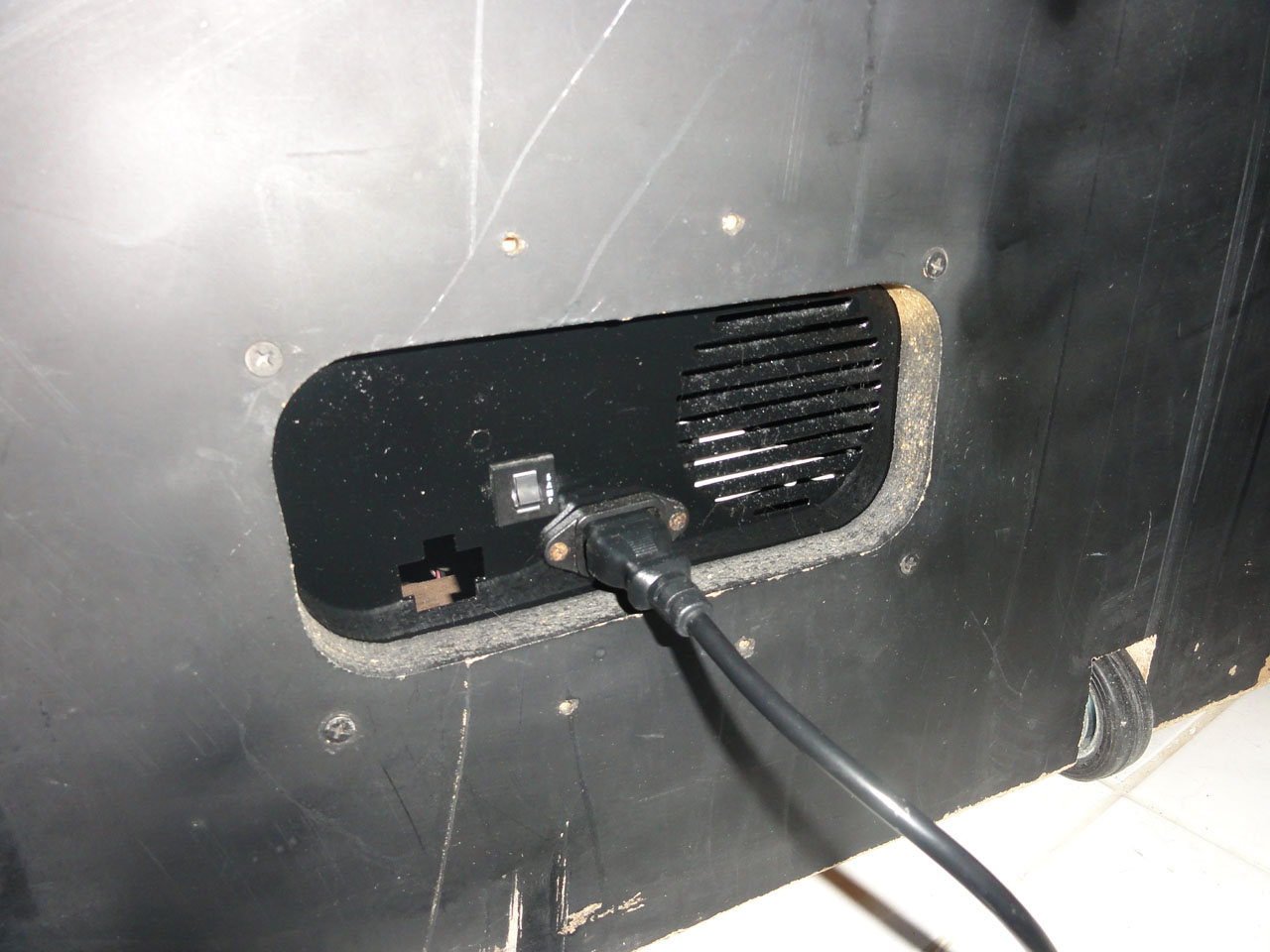
The entire back.
The control panel mounted and wired. You can make out the USB hub on the very right side of the control panel base. I almost went crazy trying to get a really nice mirror like coat of paint. I must of done 7 trips of painting and sandingon the base. Just when I was done, I thought I would put I nice clear coat on. Well it ended up driping and it most of been 20 more rounds of sanding and painting could never get the imperfections to go away. Before I decide to shoot myself in frustration. I bought some black adhesive vinyl from ebay and wrapped it in it. I really wish I had done that first!
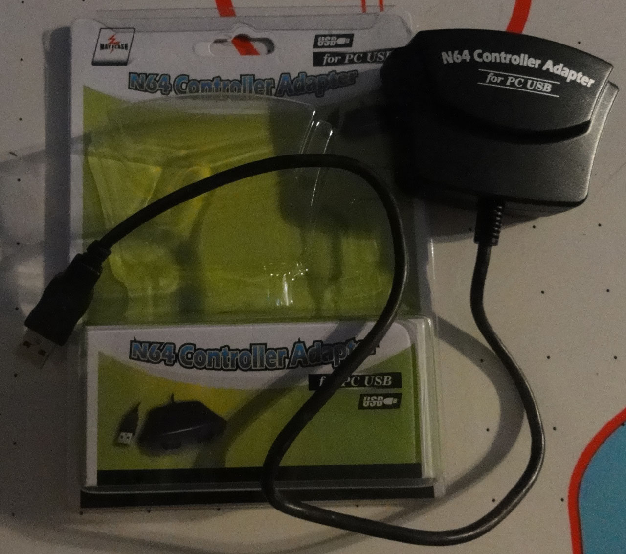
N64 controller to USB adapter.
The controllers labeled with my label maker.
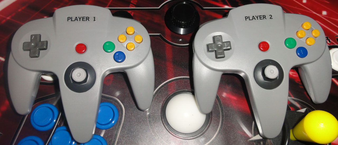
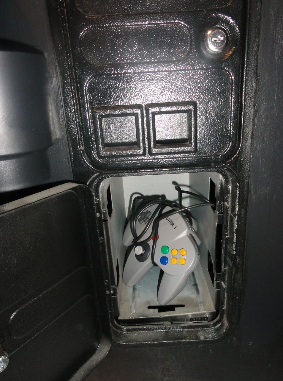
They will stay behind the left bottom coin door when not playing N64 or Dreamcast.
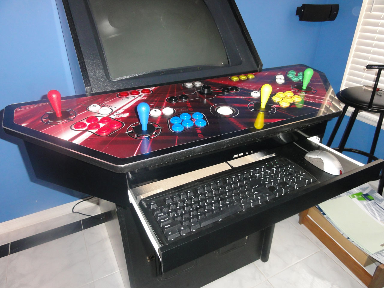
The finshed control Panel and pull out keyboard and mouse drawer.
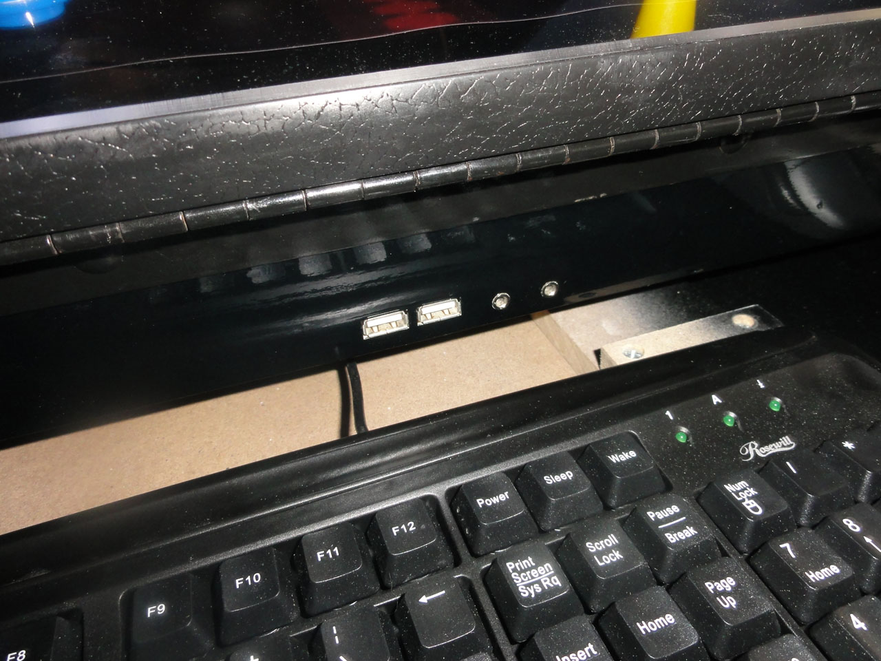
Close up on the extra usb ports and headphone jacks.
A side view of the near final cabinet.
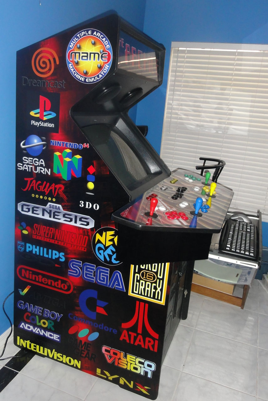
Front, just missing guns and cupholders.
AIMTrak electronics install.
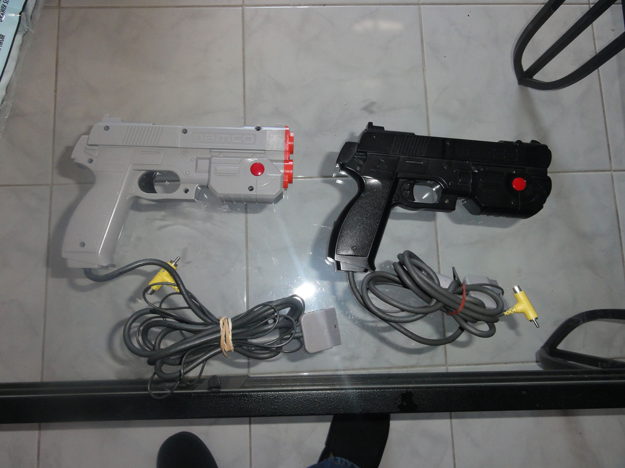
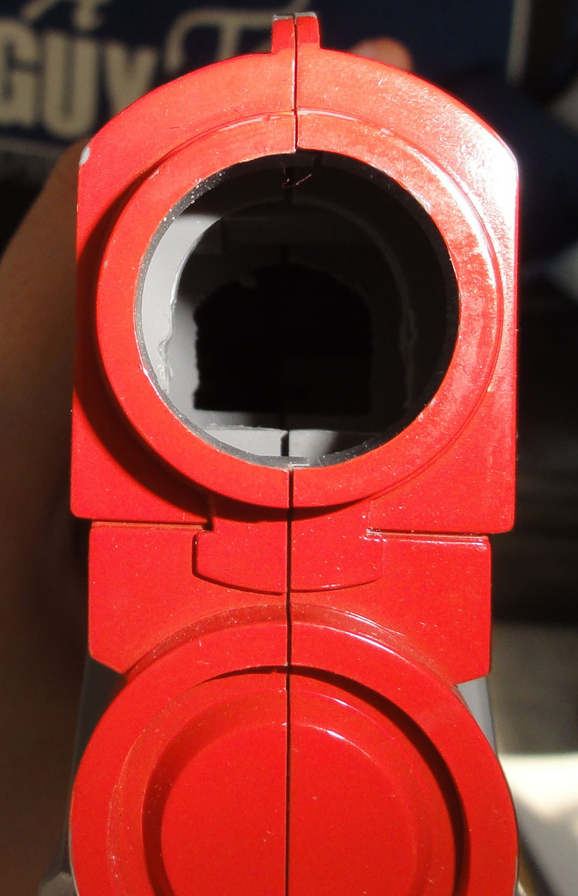
I got these old playstation guns off eBay for cheap, and they almost match Ultimarc ones.
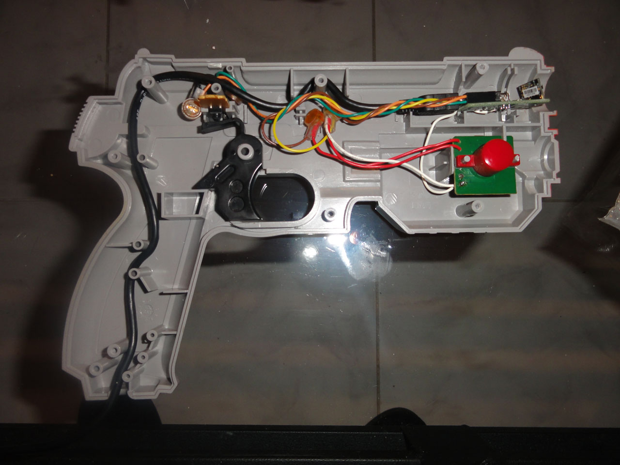
The inside with the aimtrak just laying in it's future spot.
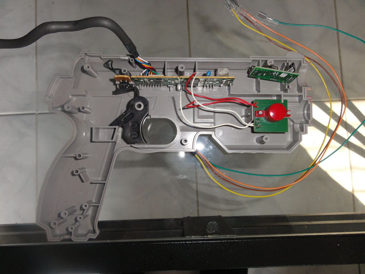
The old sensor board removed.
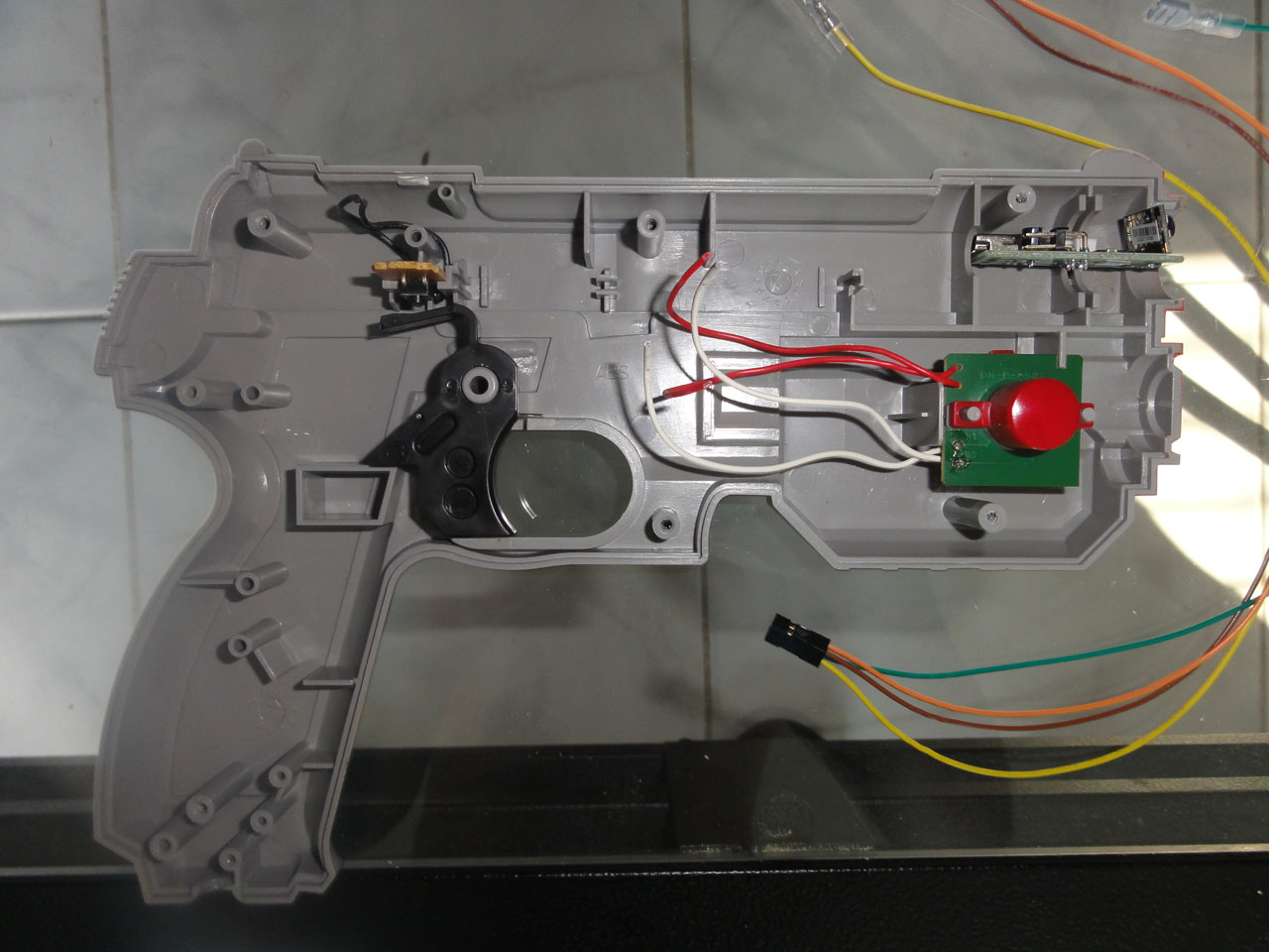
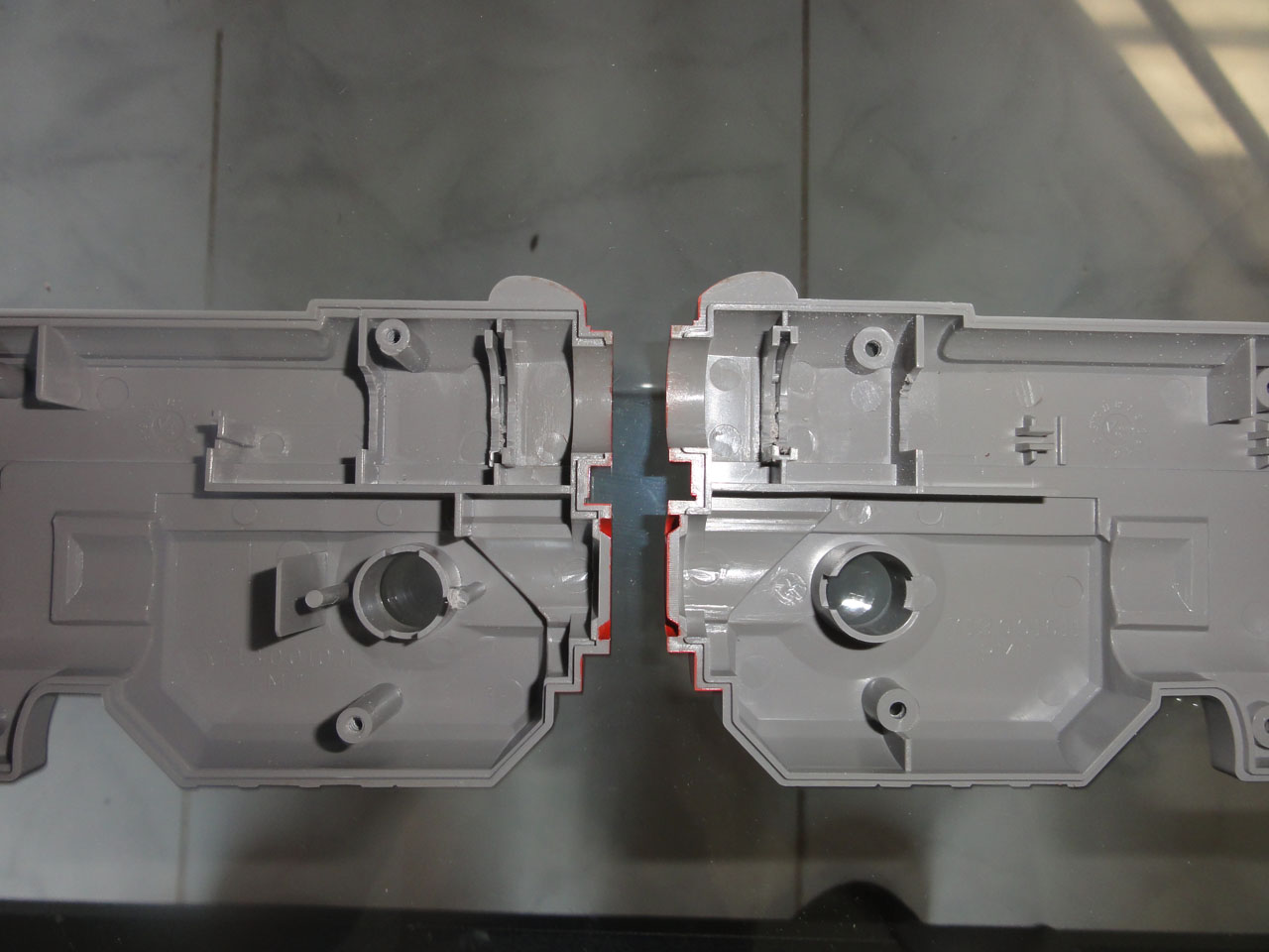
The part of the gun that needs to be cut away for the AimTrak sensor.
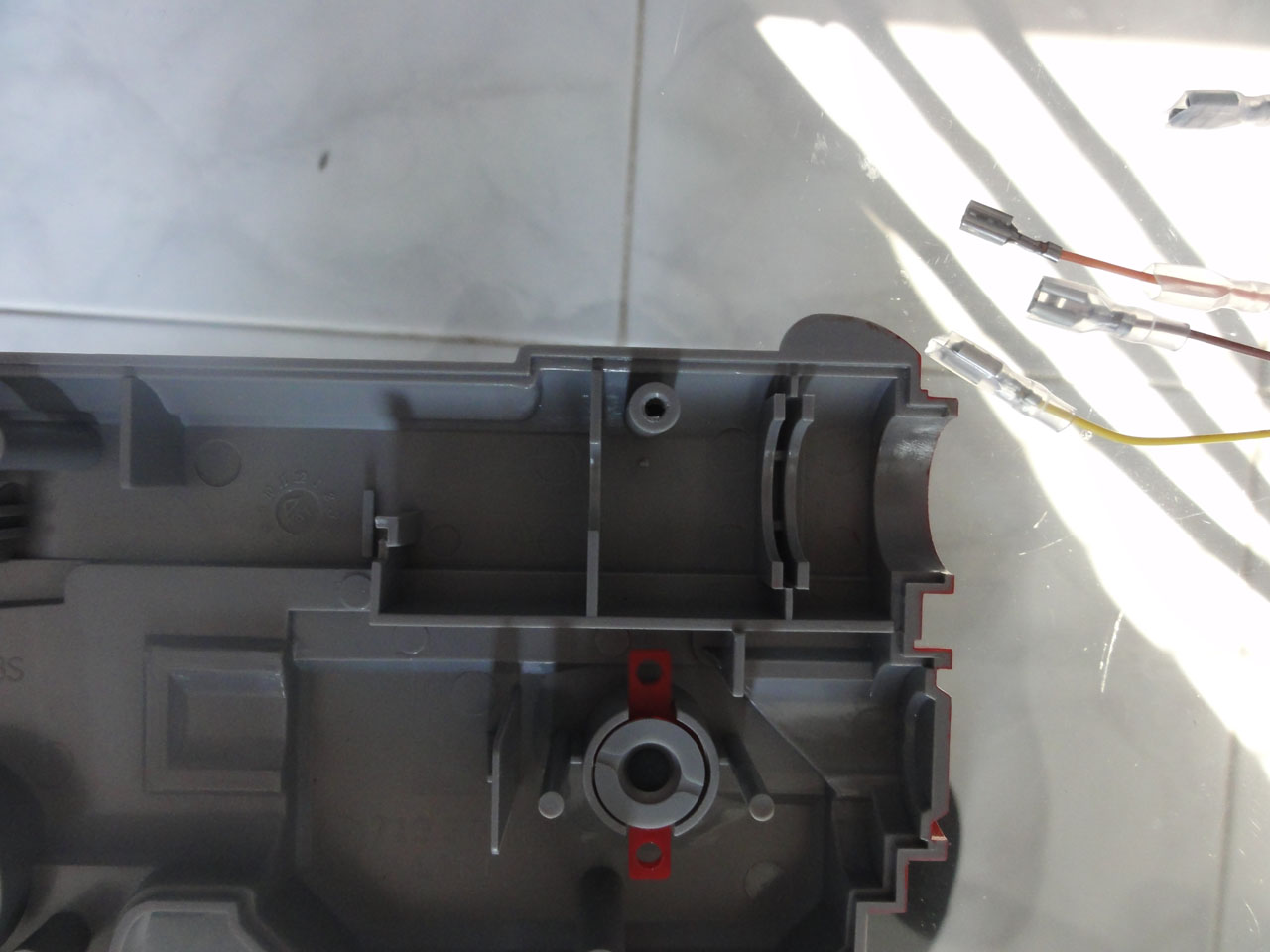
After using my dremel with cutting wheel attachment.
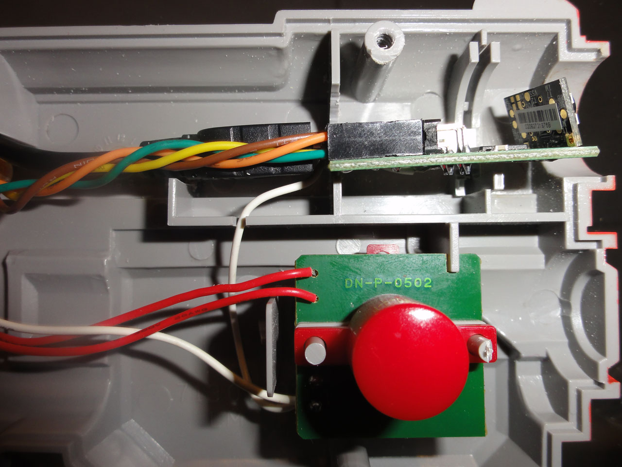
Sensor wired up to trigger, A, and B Buttons using button connectors.
Just some hot glue to hold the Aimtrak sensor in place and it is ready to go!
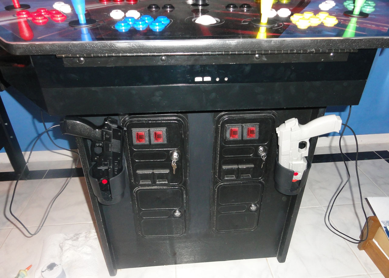
The guns mounted. I was going to cut holes for the guns to sit, but I had bought 4 cupholders and really only had place for 2. I think the other 2 cup holders work great as gun holsters.
That is it so far. Working on all the software and emulater configuration. I am going with Maximus Arcade as I absolutely love the interface, especially when I customized it with colors to match my cabinet.
Tips for others:
Always use scrap wood to test the length of cuts before you make them. (This saved me so many times!)
If you can, cut MDF and plexiglass outside. (MDF has left a mm thick dust on my everything in my garage, since I like to do my work late at night and can't do it outside)
Always where eye protection! (I had no injuries because I followed this rule. But had very hot plexi hit exposed skin, and did not feel too good)
Take your TIME! (This is the hardest one for me to follow, but I actually did a pretty good job of it.)
No matter how hard you will try, mistakes will be made. (Like my T-molding slot incident)
Install T-molding slowly inch by inch, it can and will bend and warp and make it really hard to finish.
Remember when wiring the Joysticks that Up is down, down is up, left is right, and right is left. I swapped the wires on the Ipac4 for all for players once I realized my mistake.
If any one has any questions or wants print quality versions of my artwork, post here.
James


 Home
Home Help
Help Search
 Login
Login Register

 Send this topic
 Print
Print Topic: The Archive - Simpsons Conversion Project (Read 14897 times)


