Ok, I have pretty much given up on using the GPIO to interface to the original NES connectors.
All the code suggestions I have found do not work for me.
I have order a SNES to USB adapter. From what i gather from my research, the NES and SNES controllers are basically the same, electrical connection wise.
But if anyone can help me out by showing me the code I need to read the NES controller connected to GPIO, please tell me.
As promised, here is how I modified the LED on the NES power/reset switch assembly.
First, if you do not have a digital volt ohm milliammeter (DVOM), with a diode check function, you need to get one.
The diode check function can test an led, and even tell you what the voltage drop across the LED is, which can be very good when figuring the size resistor you need.
Here is a schematic diagram of how the NES power/reset circuit board is wired.
Left shows the polarity of the Power LED before my modifications, and the right shows the polarity after my modifications.
This drawing also shows the mausberry switch connections. (Sw+, SW-, Rst+, Rst-, LED)

Ok, first pic shows my DVOM connected to the NES switch white and orange wires.
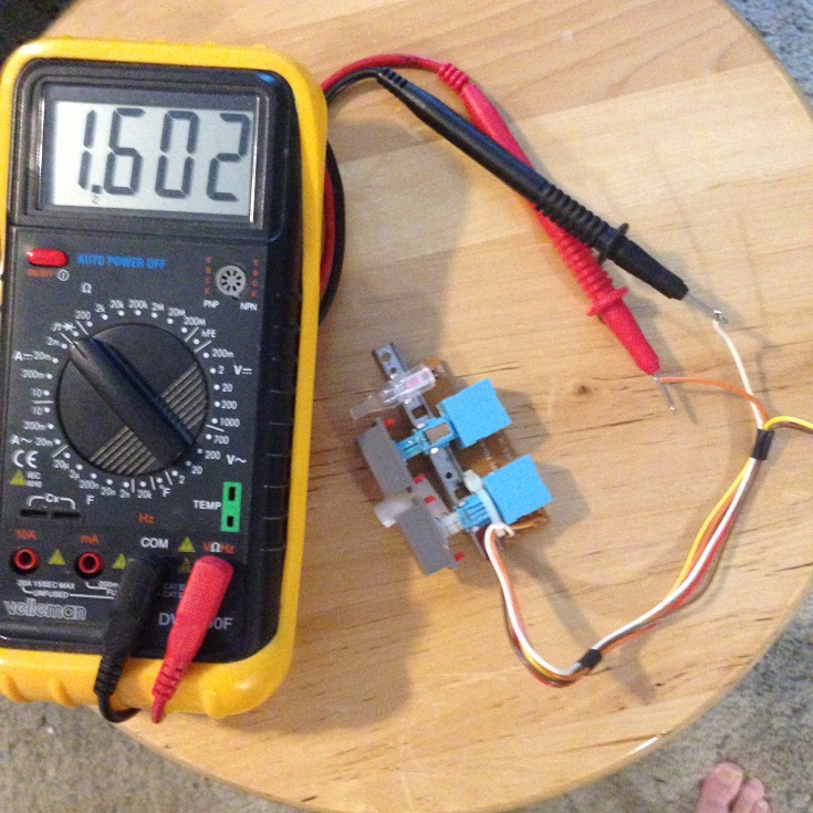
You see the red lead of the DVOM is connected to the orange wire, black lead to the white wire. The red lead of the DVOM is positive, black is negative.
The DVOM is displaying 1.602. This tells me that the LED is forward biased and current is flowing through it. The reading is also telling me that the LED is dropping 1.602 volts.
You may not be able to see it in this pic, but the LED is faintly glowing.
This test also tells me that the orange wire connects to positive and the white to negative supply.
Since the orange wire connects to both the LED and the reset button, this needs to be negative.
We can change that by reversing the polarity of the LED.
If we reverse the DVOM leads, we see no voltage drop displayed on the meter, because the LED is reverse biased and no current flows through it.
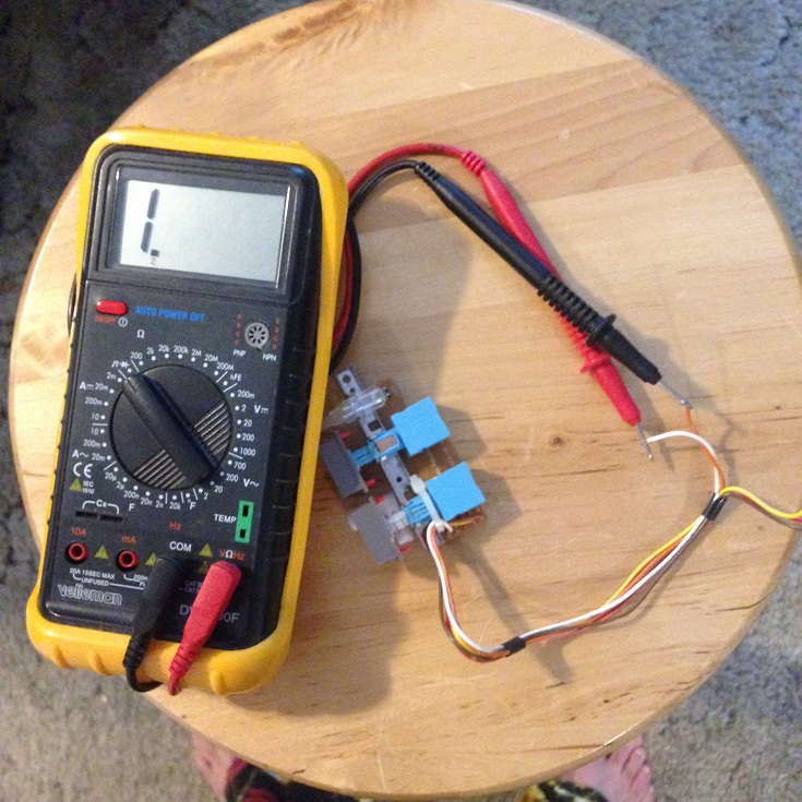
This test confirms that the white wire is negative and orange wire is positive. However, we need orange to be negative and white positive, so to quote Hammerin Harry, "Let's get busy!"
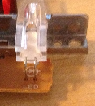
Here is a closeup of the LED in its plastic holder. Yo can see the polarity of the LED is marked on the circuit board.
Now here comes the scary part. You must remove the LED from the plastic holder thinngy.
I used a knife between the rim of the LED and the plastic and gently pried it out.

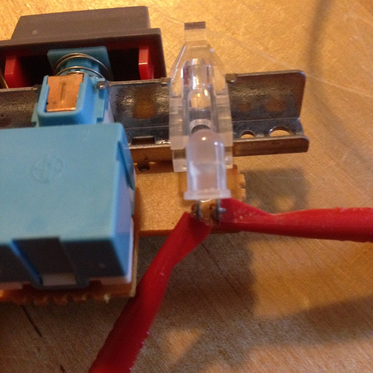
Now we attach a heat sink to protect the led from the soldering gun that is heating up and getting ready.
You can see I used test leads on each of the LED leads. This will absorb most of the heat and protect the LED.
I now flip the board over, and using braided de-soldering wick, I place the wick between the first LED solder pad and place the soldering iron on top of the wick.
The heat will flow through the wick and melt the solder. The solder is then sucked up into the wick.

This takes a few attempts to get a clean hole, I always remove iron and let it cool for a few seconds before moving the wick to a clean spot and repeating. The cooling pause is to keep from overheating the LED.
When the hole is clean, I remove the iron for about a minute then repeat the process on the other LED lead.
After the LED leads are free, flip the board over and pull out the LED. The desolder wick I used is in background. Heatsink test clips are still attached to the LED.
You can also see the LED leads are bent 90 degrees.

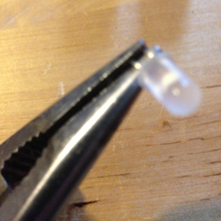
Now I put the LED is a needle nose pliers (just about any pliers or clamp should work).

I then carefully bend the leads so the LED is 180 degrees opposite what it was.
I then re-insert the LED leads into the holes of the circuit board, and push the LED back into the plastic thinngy.
I also re=attach the heatsink test leads.
I then flip the board over.

And solder the leads back.

Now the board should be ready. The LED polarity should be reversed, and the orange wire should be negative.
We can test it by connecting the DVOM back to the white and orange wires.

And we can see that the orange wire is now negative and the white is positive. The voltage drop now reads 1.593. No big deal, this is not a real expensive meter.
No picture, but I did reverse the DVOM leads to double check.
So it should be ready to hook up the mausberry switch.
Please note that my meter reads 1. when it sees an over range voltage drop. (Same as open circuit). This does not mean 1 volt, it just means it doesnt see anything, or the volt drop is so high it cant read it. (Infinity).
Your meter may read something different when the LED is reversed biased. Some meters read OL. I have seen some that read --.
If your DVOM has diode check on it, and the leads are not connected to anything, the meter will display what it shows for infinity. Mine shows 1. when not connected to anything (on diode check).
As with all test tools, read the manual that came with it if you dont understand.
These meters with diode check functions are very useful. They can check LEDs, diodes, and even transistors.
Since we use LEDs a lot in this hobby, it should be put on your necessary tool list, if you dont already have one.
Of course, if you dont have a DVOM with diode check, and dont want to buy one, you can take my word for it and reverse the LED polarity without using a meter.


 Home
Home Help
Help Search
 Login
Login Register

 Send this topic
 Print
Print Topic: Bride of Frankenstein, a R-Pi2 in a NES case, the sequel. (Read 5509 times)


