This project has taken way too long (though not nearly as long as Mission Control...) but I am finally back on track and making good progress. I'm going to play catch-up by copying my blog entries into one long post and then keep updating as we go.
COIN DOOR REVISION (Aug 14)
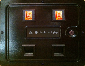
I managed to get a coin door from an original Atari Tempest cab. Actually, I now have several of the same model of coin door, but one of them I know for a fact came out of a Tempest machine. I took that door, cleaned it up and had it powder coated to look original. Then I cleaned up the backplate and coin mech parts and put it all back together. One of the other doors I found had orange coin return buttons, so I cleaned those up and installed my own graphics. Apply 12V and:
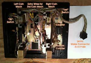
I'm very happy with it! I do not want to alter the wiring or hardware (love that I will be able to say it is an original Tempest coin door) so I needed to figure out the pinouts on the 24 pin Molex (4x6) connector. Using a multimeter I was able to pretty quickly determine:
1. Center Coin Switch
3. Right Coin Switch
3. Left Coin Switch
4. Reset ON & Momentary Switch
5. Tilt Switch
6. Switch Common (All Coin, Reset, Tilt)
7. Solenoid Common
8. Center Solenoid
9. Right Solenoid
10. Left Solenoid
11. Extra Counter A1
12. Extra Counter A2
13. Top Counter 1 (apply 6VDC either way to increment)
14. Top Counter 2
15. Bottom Counter 1 (apply 6VDC either way to increment)
16. Bottom Couter 2
17. Extra Counter B1
18. Extra Counter B2
19. Coin Return Lights Power (12VDC)
20. Coin Return Lights GND
21. Not Used
22. Not Used
23. Chassis GND
24. Chassis GND
Currently I am using 12VDC incandescent bulbs that I bought at the auto parts store.
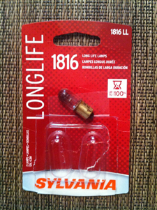
I have ordered LED bulbs that are packaged in a T3.25 Bayonet base. Both are orange, one is a dome covered package and the other is open. I will try them both and post the results of the comparison.
I will be using the "Test" switch as my free-play switch.
LONG TIME COMIN' (Aug 15)
After too long. Way too long. We are finally back on track. Let me recap...
February 2009: For my 45th birthday BFG offers to buy me a Tempest cab or pay for the components to build my own. I choose the "build your own" option and start on the journey.
January 2010: After almost a year of planning and acquiring parts we found out that a friend of mine had a full size CNC router table. I updated the plans to take advantage of this and have everything dado'd into the sides. Unfortunately, after another year plus we still hadn't been able to get aforementioned 'friend' to cut a single piece of wood.
August 2011: The cabinet guy that does work for my company turns out to have a full size CNC router table! Not wanting to get my hopes up, I sent him the plans and crossed my fingers.
Today I met with him for an hour to discuss details. He called this morning to tell me he had cut the sides and CP out of scrap material to test and wanted me to come see them! I almost wet myself.
In addition to being able (and willing and ready) to cut the big pieces that I designed to be CNC routed, Bryce (that's his name) is also going to cut the rest of the parts and has offered several helpful ideas to make the assembly go smoother.
We are going to get this thing built!!!!
SOMETHING OLD, SOMETHING NEW... (Aug 26)
I got a hold of an original Tempest Control Panel with all the original controls in it. That's right, an original Tempest spinner and two Atari "volcano" buttons. Sweet! I already have a TurboTwist 2 from GGG, but I started thinking that it would be really cool to have the Tempest spinner in my cab. My first question was if the Tempest spinner would be a good controller for a MAME application. I posted on the BYOAC board and got a reply from RandyT (owner/operator of GGG):
For Tempest, the original control will be great. But, if you plan to play games which used a dial (potentiometer) based control, or games which require high resolution, like Arkanoid, you will no longer have the optimal resolution for accurate gameplay.
Of course, I would expect him to be biased toward his spinner, but I already bought one of his so it isn't like he is losing a sale if I go with the Tempest spinner. I still haven't decided, and in fact would like to be able to test both, so.....
First I took the spinner apart and Steve made a longer shaft so it would mount under my 3/4" CP instead of the thin metal CP of the Tempest cab.
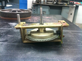
The old shaft is resting in the left mounting hole. The new shaft is assembled in the spinner. A little lube and she spins like new!
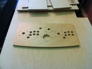
Second, I redesigned the CP to accommodate the Tempest spinner. This meant moving some things, which meant redesigning the CP Overlay, which if I was going to do meant I could fix whatever, so....
I added the volcano buttons as P1 and P2 button onto the CP. Worried that some day they might break and not be replaceable, I designed an insert for a standard button hole to mount the smaller volcano buttons in. If they ever go bad and can't be fixed or replaced I can pull out the insert and replace with a standard button.
Additionally, since my cab is orange and black, I didn't really want red lens in the buttons. This is a problem as they have not been made for a long time and they were never made clear or orange, just black and red. A lot of searching and reading on the BYOAC board led me to <a href="
http://www.flickr.com/photos/sky-lab/sets/72157603642874378/">this guy</a> who was casting his own replacement lens for the same buttons. I contacted him and he is making me a set of lens for my buttons!
Finally I had to adjust my CP Overlay to accommodate the parts movement and additions. During that process I dropped the numbers for P1 and P2 and created neon Atari player people like were on the early Atari games (including Tempest!) and the result is:
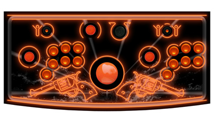
I like this version a LOT! Now I can mount either the TurboTwist 2 or the Tempest spinner and see how I like them in real game play. I get the original Atari cone buttons and P1 and P2 and I get the little Atari guys and all it cost me was about $90 for the original control panel, a few hours in the shop to make a new shaft and mounts for the volcano buttons, several hours redoing the CP Overlay art and the $ to reprint it. I'd say that's a bargain at twice the price
 9 LIGHTS
 (Aug 26)
Actually the correct term is lamp. Some people call them bulbs, but that actually only refers to the glass globe that protects the filament from the rapid oxidation of the air. Of course, LEDs don't oxidize and so are often packaged very differently.
I ordered and tested 9 different lamps to light the coin return button in the coin door.
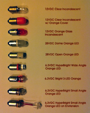
Frankly, the one I like best is the 12VDC Orange Glass Incandescent. The LEDs are not as bright and don't really create as much color as the "standard" lamp. I can see how the reduction of heat output and the longer life would be tempting, but I am going for look and feel here and I like the way the old school lamps look and feel.
Anybody need 2 each of 6 different LED lamps?
ORANGE BUTTONY GOODNESS (Sep 1)
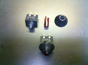
Sean, the guy I told you about, sent me a pic of the test casting of my new Atari 'volcano' button lenses.
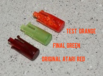
The bottom button is an original Atari red lens. The middle one is a finished lens in green that he had already made, and the top one is a test cast in orange. The final cast will be done in his pressure chamber to remove the bubbles so it looks like the green one (only orange)!
Thought it might be a good idea to test the switches I have, so I had Ky, one of our electrical engineers, put them on a meter and verify that the contacts work (I'm a mechanical engineer and electricity scares me...). Then Ky hooked up 5VDC to test the LEDs and surprise, surprise, surprise...they are RED.
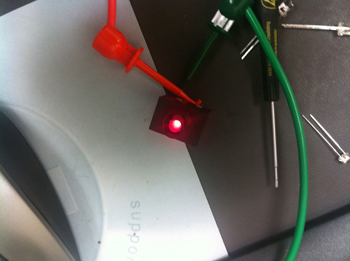
I don't know why I didn't think about that. Red lenses means they could have used white LEDs, however, Ky reminded me that white LEDs were not available in the late 1970's. So, a red LED is going to make my orange lens look red. No good.
So, Ky swapped out the LEDs for new ORANGE ones! Not an easy task as the switch is held together with brads and we didn't want to try to take it apart. Ky ended up chopping up the old LED from the top until he could clip out the remaining leads. Then it was fairly simple (for him!) to solder in new orange LED goodness.
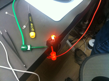
They are brighter at a lower current draw too. If I want them dimmer I can always increase the value of the resistor.
Meanwhile, Steve is machining the holders for these buttons. Here is the drawing in the shop of the part:
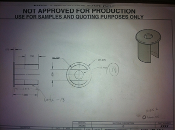
and here it is on the lathe being machined:
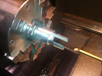
Steve machined the threads onto both ends of a piece of aluminum stock, then put it in the EDM machine and cut out the large slot for the switch housing to go into, then back into the lathe to bore the hole for the switch to stick through and then part it off. After it is cleaned up and polished it will go to the platers to be hard anodized black.
Also, tomorrow I go to Reid Cabinetry to cut the cabinet parts out!!!
Woot!
SHINY = GOOD (Sep 2)
Button mounts are finished and ready to go to the platers:
Mounts without switches in them....
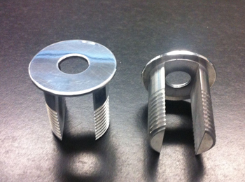
Mounts with switches installed...
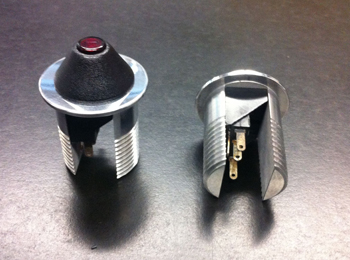
They will be hard anodized black before they are completely finished.
THE FIRST CUT IS THE DEEPEST (Sep 1)
Went to Reid Cabinetry today and cut some wood! We were a little short on time so we only cut one side and some of the internal pieces, but it was a blast getting things going.
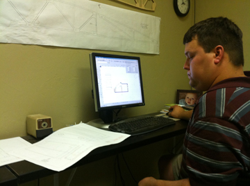
All my drawings are in PowerCADD, so I export DXF files and send them to one of my engineers. Dustin opens the files in AutoCADD and removes all the elements that are not related to a cutting path and makes sure all the lines connect and the path is continuous. He then saves the cleaned up drawing as a DXF. We send that file to Bryce and he imports it into his software to generate cutting paths and tool id info for the router table.
First we verified that we were cutting the right parts from the right material in the right orientation:
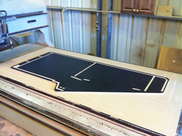
Then with the program sent to the router table we placed the material (5/8 birch ply laminated on the inside with black formica) on the table:
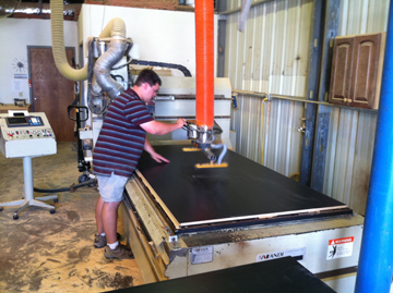
After Bryce set the tool depth and rechecked everything he pushed the button and the cutting started:
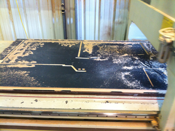
Once all the cutting was done you could see the various pieces still held in place by the vacuum:
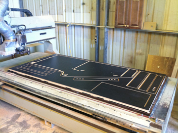
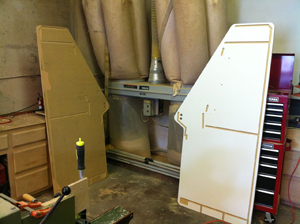
Then we separated everything and we could look at one side finished and ready to be assembled:
We are using angled cutters to cut the beveled edges of the pieces for below the CP and for the marquee light box. The edge is perfect and once we join the pieces together the finish and fit should be fantastic.
It was a great day for yummy arcade goodness! Stay tuned....


 Home
Home Help
Help Search
 Login
Login Register

 Send this topic
 Print
Print Topic: Cowboy Arcade - Updated 6/25/2017 (Read 38987 times)


