Main Restorations Software Audio/Jukebox/MP3 Everything Else Buy/Sell/Trade
Project Announcements Monitor/Video GroovyMAME Merit/JVL Touchscreen Meet Up Retail Vendors
Driving & Racing Woodworking Software Support Forums Consoles Project Arcade Reviews
Automated Projects Artwork Frontend Support Forums Pinball Forum Discussion Old Boards
Raspberry Pi & Dev Board controls.dat Linux Miscellaneous Arcade Wiki Discussion Old Archives
Lightguns Arcade1Up Try the site in https mode Site News

Unread posts | New Replies | Recent posts | Rules | Chatroom | Wiki | File Repository | RSS | Submit news


Author Topic: The Smash Pad - kittens and cleaning and stools - oh my!  (Read 52016 times)

0 Members and 1 Guest are viewing this topic.

Seith

  • Trade Count: (0)
  • Full Member
  • ***
  • Offline Offline
  • Posts: 402
  • Last login:September 08, 2018, 10:50:41 am
Re: The Smash Pad - Speaker Given Lip By Overzealous Gamer
« Reply #80 on: July 04, 2012, 08:24:40 pm »
I realize I *may* be overdoing it with the pics per post... I promise I will split it up into more posts from here on in... next week I have off, so I hope to make some major advancements in the project.

Seith

  • Trade Count: (0)
  • Full Member
  • ***
  • Offline Offline
  • Posts: 402
  • Last login:September 08, 2018, 10:50:41 am
Re: The Smash Pad - Speaker Given Lip By Overzealous Gamer
« Reply #81 on: July 16, 2012, 04:28:54 pm »
It's been a while since i've posted updates, and I have a lot to post... let's see, we've gone some weekends now, as well as an entire 10 consecutive days off where i made tons of progress...

Ordered some speaker grill from amazon:


Created a wider recess to fit the cut grill for the speakers:


The finished speaker panel:

Seith

  • Trade Count: (0)
  • Full Member
  • ***
  • Offline Offline
  • Posts: 402
  • Last login:September 08, 2018, 10:50:41 am
Re: The Smash Pad - Speaker Given Lip By Overzealous Gamer
« Reply #82 on: July 16, 2012, 04:35:24 pm »


Created a lip for the speaker grill on the back of the cab.  Later I will be cutting an access door where that grill is.

Seith

  • Trade Count: (0)
  • Full Member
  • ***
  • Offline Offline
  • Posts: 402
  • Last login:September 08, 2018, 10:50:41 am
Re: The Smash Pad - Speaker Given Lip By Overzealous Gamer
« Reply #83 on: July 16, 2012, 04:40:52 pm »
Printed out a 1:1 layout of the control panel holes with centering guides, taped it to the control panel:


Thinking ahead, I created a sandwich.  from top to bottom, you have the production CP, the plexiglass, another piece of 5/8" MDF to act as a template in case I need it in the future, and a piece of scrap to blowout into when drilling:

Seith

  • Trade Count: (0)
  • Full Member
  • ***
  • Offline Offline
  • Posts: 402
  • Last login:September 08, 2018, 10:50:41 am
Re: The Smash Pad - Speaker Given Lip By Overzealous Gamer
« Reply #84 on: July 16, 2012, 04:47:06 pm »
Began drilling... i was really nervous about this step but truth be told, it has been the most fun of the project so far.


Bought a cheap 3" hole saw at Canadian Tire for 10 bucks, began cutting through:


Partway through, the hole saw started smoking  :o


I had to pop out the biscuit once i was about halfway through to make room for the rest of the wood I was taking out.  Man, that wood really gets lodged in there:


Hey, glad to see there were no cracks in the plexi from drilling!   :applaud:

Seith

  • Trade Count: (0)
  • Full Member
  • ***
  • Offline Offline
  • Posts: 402
  • Last login:September 08, 2018, 10:50:41 am
Re: The Smash Pad - Speaker Given Lip By Overzealous Gamer
« Reply #85 on: July 16, 2012, 04:49:45 pm »
And now, the part of the project that every person who goes through this is most proud of... you could say this is the turning point... the picture that waters the seed that won't stop growing.... i give you the control panel!


Of course, there is still more work to be done before declaring it finished, but still... this picture is very exciting.

Seith

  • Trade Count: (0)
  • Full Member
  • ***
  • Offline Offline
  • Posts: 402
  • Last login:September 08, 2018, 10:50:41 am
Re: The Smash Pad - Holy Moly
« Reply #86 on: July 17, 2012, 09:02:46 am »
Here is a shot of the CP with template copy and plexi, all drilled:


Went ahead and gave a 45 degree bevel to the edge of the plexiglass around the trackball lip:

Seith

  • Trade Count: (0)
  • Full Member
  • ***
  • Offline Offline
  • Posts: 402
  • Last login:September 08, 2018, 10:50:41 am
Re: The Smash Pad - Holy Moly
« Reply #87 on: July 17, 2012, 09:14:39 am »
Moved on to extending the pots from the logitech z2300 speaker remote for mounting in the kickplate right under the control panel box:


Video of the whole kit and kaboodle in action (mind the skipping, my phone was streaming wefunk internet radio)

Seith

  • Trade Count: (0)
  • Full Member
  • ***
  • Offline Offline
  • Posts: 402
  • Last login:September 08, 2018, 10:50:41 am
Re: The Smash Pad - Holy Moly
« Reply #88 on: July 18, 2012, 06:01:25 pm »
More holes, more holes..

Drilled five holes into the top of the kickplate/coindoor panel:


3x 1", 2x 7/8", all with the forstner bits.


Mounted Neutrik USB jacks as well as a Neutrik NJ3 audio jack I got for cheap using http://www.froogle.com/

Seith

  • Trade Count: (0)
  • Full Member
  • ***
  • Offline Offline
  • Posts: 402
  • Last login:September 08, 2018, 10:50:41 am
Re: The Smash Pad - Holy Moly
« Reply #89 on: July 19, 2012, 12:26:26 am »
I was initially going to fasten in the volume and bass pots using ebony wood putty:


But after 48 hours the putty hadn't hardened in the holes and was still soft and malleable, despite saying "quick-dry" on the container...  :badmood:

So I had to pull the pots out and clean them up some...


And went out and got some Automotive goop to fill the holes with.  This stuff is thick like molasses and very viscous, but I didn't want it to drip too much, so I masked the pots using some cardboard and tape:


Then applied some Goop into the holes from the back:


Came back the next morning and it had hardened up real nice.  It hardens to a solid rubber state, and bonds excellently with the MDF.  Definitely recommended for this particular application.

I removed the masking and noticed there was still some run-down on the bass pot:


A little exacto knife work cleaned it up nicely:


That's one panel down... onto the trackball.

Seith

  • Trade Count: (0)
  • Full Member
  • ***
  • Offline Offline
  • Posts: 402
  • Last login:September 08, 2018, 10:50:41 am
Re: The Smash Pad - Holy Moly
« Reply #90 on: July 19, 2012, 12:30:39 am »
Measured and cut the trackball hole:


Also recessed the plate by 1/8":


Mounted the trackball with plexi on top:


Also got another order in the mail, my coin mech from Happ arrived.  Calibrated for 25 cents Canadian:


Seith

  • Trade Count: (0)
  • Full Member
  • ***
  • Offline Offline
  • Posts: 402
  • Last login:September 08, 2018, 10:50:41 am
Re: The Smash Pad - Holy Moly
« Reply #91 on: July 19, 2012, 12:32:28 am »
Cut the back piece into three to make an access door:


Took the lowest of the three pieces and mounted a power port with switch in there:


Seith

  • Trade Count: (0)
  • Full Member
  • ***
  • Offline Offline
  • Posts: 402
  • Last login:September 08, 2018, 10:50:41 am
Re: The Smash Pad - The Glue-Up
« Reply #92 on: July 19, 2012, 08:39:50 am »
So the next step in this project is to get this bad-boy upright and standing and glued together, so I can finally move on to wiring.

However, there are a few things to consider before I whip out my bottle of carpenter's glue and go to town on it:

1.  How are the marquee lights going to be mounted?
2.  Will the bracket solution work for my monitor and be fallproof?
3.  Where will the sub box sit?  Ideally, it should be raised so that the sound travels out of the back access door which will have a grate on it to allow for venting as well.

Question 2 is the one that is burning on my mind the most right now.  I am using a CRT television, and we plan to have it sit on it's corner clips, recessed into planks of wood and suspended in the air on such a short point of load-bearing.  My fear is that after a month and a half I am going to have a TV-sized mess to clean up inside the cab.  I guess my biggest concern is that I haven't seen anyone else mounting their monitors like I have.  At any rate, onto the pics (I am almost caught up to where I am in the project right now, pic-wise.)


Used "No More Nails" to secure the TV brackets:


Also glued the speaker grills into their recesses (still have to do the rear access door):


Seith

  • Trade Count: (0)
  • Full Member
  • ***
  • Offline Offline
  • Posts: 402
  • Last login:September 08, 2018, 10:50:41 am
Re: The Smash Pad - The Glue-Up
« Reply #93 on: July 19, 2012, 11:25:18 pm »
Here's how I plan to mount the monitor.


Left side of picture is the front view of where the monitor will sit and on the right is a cross-section of the side of the cab.  That diagonal box is a piece of wood that has a groove cut into it that reaches back to a slot pointing downward (where the black is).  So the monitor will slide in with it's four corner clips following the valley cut into the wood until it reaches the back of the bracket, at which point it will slide down into the slots that were cut for it and rest it's weight on those.  My worry here is that 1, the monitor isn't bolted to anything, and 2, the clips don't really go that deep into the slot, so i'm afraid the monitor will slide out one way or another.

Here's a better pic of the brackets I have glued to the cab already:


Does this seem feasible?  Or would it be a better idea to do up a frame that can be bolted to the clips and do away with the bracket idea altogether?
« Last Edit: July 20, 2012, 08:12:45 am by Seith »

Seith

  • Trade Count: (0)
  • Full Member
  • ***
  • Offline Offline
  • Posts: 402
  • Last login:September 08, 2018, 10:50:41 am
Re: The Smash Pad - The Glue-Up
« Reply #94 on: July 23, 2012, 10:55:03 am »
Cut some interior shelving and positioned it in the cab, one shelf for the sub and one shelf to hold the guts of the TV:


Dry-fit some of the cross panels to get a feel for where everything will rest:


Also came up with a solution for the marquee light panel; I wanted it removable so that I could access the speakers and the exhaust fan on top.  Used liquid nail to fasten a butt-piece to the side, and installed some sliding cellar locks on both sides of the panel:


And created a recess in the cross pieces that will hold the glass, 1/8" deep, 1/2" long:


Seith

  • Trade Count: (0)
  • Full Member
  • ***
  • Offline Offline
  • Posts: 402
  • Last login:September 08, 2018, 10:50:41 am
Re: The Smash Pad - The Glue-Up
« Reply #95 on: July 24, 2012, 12:30:07 pm »


 :angry:

So I go to glue the cabinet up this weekend, and lo and behold, we had a bit of a mismeasurement when drilling dowel holes on the left side piece.  Apparently my dad thought the roof of the cab was supposed to butt up with the back spine of the side piece, not the front.  And we went a whole month and a half without dry-fitting both the top and back boards to the left wall somehow.

The trouble is, at this point I had already glued up the back pieces as well as one of the shelves.

We had also already glued the dowels into the holes for the top piece, and those things were NOT budging once they were hammered in.

So we had to act fast.  We put the top piece up where it was supposed to be and rough-traced around the ends of the dowels, then measured the center of the incorrect dowel holes to get centered for our new holes.  The first pic is the result of that.

Unfortunately our measurement was a little off, which became apparent once we glued the piece on:


 :banghead: D'OH!

Luckily this little blemish on the project is located where nobody will ever see it, but I will have to live with that little bit of knowledge banging around in my noggin forevermore...

Lesson learned, measure x 1 million, cut once.

Anyway... onto the cab, all glued up:


Seith

  • Trade Count: (0)
  • Full Member
  • ***
  • Offline Offline
  • Posts: 402
  • Last login:September 08, 2018, 10:50:41 am
Re: The Smash Pad - The Glue-Up
« Reply #96 on: July 25, 2012, 05:58:42 pm »


Modified the marquee slightly... still tossing ideas around for the control panel... i hate staring at a blank screen and not being able to get momentum when it comes to artwork! :hissy:

mcseforsale

  • Trade Count: (0)
  • Full Member
  • ***
  • Offline Offline
  • Posts: 1471
  • Last login:April 09, 2024, 03:07:41 pm
  • Creepy Mario Dude
Re: The Smash Pad - The Glue-Up
« Reply #97 on: July 26, 2012, 09:24:17 am »
Black caulk? 

http://www.foxnews.com/leisure/2012/07/24/mystery-surrounds-wireless-car-key-blackout-in-new-york-city/?intcmp=features

AJ


 :angry:

So I go to glue the cabinet up this weekend, and lo and behold, we had a bit of a mismeasurement when drilling dowel holes on the left side piece.  Apparently my dad thought the roof of the cab was supposed to butt up with the back spine of the side piece, not the front.  And we went a whole month and a half without dry-fitting both the top and back boards to the left wall somehow.

The trouble is, at this point I had already glued up the back pieces as well as one of the shelves.

We had also already glued the dowels into the holes for the top piece, and those things were NOT budging once they were hammered in.

So we had to act fast.  We put the top piece up where it was supposed to be and rough-traced around the ends of the dowels, then measured the center of the incorrect dowel holes to get centered for our new holes.  The first pic is the result of that.

Unfortunately our measurement was a little off, which became apparent once we glued the piece on:


 :banghead: D'OH!

Luckily this little blemish on the project is located where nobody will ever see it, but I will have to live with that little bit of knowledge banging around in my noggin forevermore...

Lesson learned, measure x 1 million, cut once.

Anyway... onto the cab, all glued up:


Seith

  • Trade Count: (0)
  • Full Member
  • ***
  • Offline Offline
  • Posts: 402
  • Last login:September 08, 2018, 10:50:41 am

Seith

  • Trade Count: (0)
  • Full Member
  • ***
  • Offline Offline
  • Posts: 402
  • Last login:September 08, 2018, 10:50:41 am
Re: The Smash Pad - Wire We Here?
« Reply #99 on: July 31, 2012, 09:47:39 am »
Applied T-Molding:


Notched the underside to allow for proper wrap-around the outside edges:


Had to cut the T-Molding to properly reach into the inside edges:


Seith

  • Trade Count: (0)
  • Full Member
  • ***
  • Offline Offline
  • Posts: 402
  • Last login:September 08, 2018, 10:50:41 am
Re: The Smash Pad - Wire We Here?
« Reply #100 on: July 31, 2012, 09:52:13 am »
Got some time to drill a cable hole in the back of the CP box:


Also got to mount the joysticks:


And began the wiring process:


Had to apply some Liquid Nail and Gorilla Glue to the grill on the top of the cab in one of the corners that didn't take strong enough with the carpenter's glue, so that the 120mm chassis fan didn't weigh it down:


Also extended the wire out of the fan to about 7-8' length:


Seith

  • Trade Count: (0)
  • Full Member
  • ***
  • Offline Offline
  • Posts: 402
  • Last login:September 08, 2018, 10:50:41 am
Re: The Smash Pad - Wire We Here?
« Reply #101 on: July 31, 2012, 01:05:17 pm »
Attached the NovaMatrix Linx to the board I had set up:


Wired and plugged in... testing:


Seith

  • Trade Count: (0)
  • Full Member
  • ***
  • Offline Offline
  • Posts: 402
  • Last login:September 08, 2018, 10:50:41 am
Re: The Smash Pad - Wire We Here?
« Reply #102 on: July 31, 2012, 01:07:54 pm »
Got the caster panel on the bottom, here it is drying (used Gorilla Glue this time instead of carpenter's glue):


Also drilled a hole in the back next to the power for PC on button (which will power the rest of the cab on):


Seith

  • Trade Count: (0)
  • Full Member
  • ***
  • Offline Offline
  • Posts: 402
  • Last login:September 08, 2018, 10:50:41 am
Re: The Smash Pad - Wire We Here?
« Reply #103 on: July 31, 2012, 01:29:32 pm »
So here I am at about 80% done the cab, and now I turn to the community for creative input.  I am no graphic design wizard, by any stretch of the imagination, and for the entire run of the project, the graphics side of things seem to be the spot where I wrestle with my own brain the most.  However, I have come out at least with a logo that I can honestly say I am happy with:

http://www.youtube.com/watch?feature=player_detailpage&v=53Ra0KM6QLk#t=418s

That was done way back at the end of 2010.  Fast forward to this year when I come to revisit the logo and see what I could do to make a marquee out of it, and I came up with this initially:


Just a few weeks ago, I looked at that marquee and thought it was too "plain".  I decided to add some beams:


Then I took the inspiration for that and applied it to the CP overlay yesterday:


I tried with a slightly lessened gradient to the beams, to closer match the marquee:


So here I am today, looking for creative input and criticism. 

  • Color:  Not sure if this will pop properly with red t-molding.  Buttons on surface will be red for P1 and blue for P2, although I am not averse to purchasing more of one color or the other to make everything the same, or an entirely different color altogether that may look better.  Input?
  • Design:  I was going for a simple line type of thing, very minimal and basic, but I worry that in 2-3 years it will look blah.  I like the lines leading from all directions toward the logo, it brings the eyes to it.  The lines also work to frame the trackball.  Any suggestions as to things I could do to maybe punch it up some?  I don't want to make it TOO overpowering, but a little more excitement would be ideal.  Or is it fine?

Fire away with thoughts, opinions, suggestions, what is right about it, what is wrong about it?

Also feel free to drop any suggestions you have on the marquee if you have any, i'm open to ideas.

krick

  • Trade Count: (+1)
  • Full Member
  • ***
  • Offline Offline
  • Posts: 2006
  • Last login:February 08, 2023, 08:30:27 pm
  • Gotta have blue hair.
Re: The Smash Pad - Wire We Here?
« Reply #104 on: July 31, 2012, 01:48:17 pm »

Also drilled a hole in the back next to the power for PC on button (which will power the rest of the cab on):


Probably too late now, but why didn't you put the button on top on the right side in the back like a factory cabinet?

I picked up a push button switch from radio shack (see below) and mounted it in the spot where my cabinet originally had a toggle switch.  The button is mounted to a metal plate that's screwed to the inside of the cabinet.  The button pokes out through a hole that's roughly twice the diameter of the button.  That way, it is completely recessed so nobody can accidentally bump it.

RadioShack Momentary Switch
Normally open. Includes one red and one black. Pkg. of 2
Catalog #: 275-609
$3.69
http://www.radioshack.com/product/index.jsp?productId=2062496

Hantarex Polo 15KHz
Sapphire Radeon HD 7750 2GB (GCN)
GroovyMAME 0.197.017h_d3d9ex
CRT Emudriver & CRT Tools 2.0 beta 13 (Crimson 16.2.1 for GCN cards)
Windows 7 Home Premium 64-bit
Intel Core i7-4790K @ 4.8GHz
ASUS Z87M-PLUS Motherboard

Seith

  • Trade Count: (0)
  • Full Member
  • ***
  • Offline Offline
  • Posts: 402
  • Last login:September 08, 2018, 10:50:41 am
Re: The Smash Pad - Wire We Here?
« Reply #105 on: July 31, 2012, 03:15:43 pm »
That's a good suggestion, but the rationale I had was that it was so close to the modular plug port on the back that someone would have to jam really hard on the cab from the front with something at a strange angle behind the cab to actually hit that button, as the modular cable will be coming out of the rear of the cab at a perpendicular angle to the panel surface.

I suppose if I wanted to, I could always recess the button hole like you suggest if it becomes too much of an issue.

Seith

  • Trade Count: (0)
  • Full Member
  • ***
  • Offline Offline
  • Posts: 402
  • Last login:September 08, 2018, 10:50:41 am
Re: The Smash Pad - Looking for feedback on Artwork
« Reply #106 on: August 09, 2012, 12:54:38 pm »
More pics, this time of control panel wiring:


Also put an Exit button on the side of the box:


griffindodd

  • Trade Count: (+1)
  • Full Member
  • ***
  • Offline Offline
  • Posts: 1514
  • Last login:June 29, 2023, 02:43:19 pm
  • Builds Stuff
Re: The Smash Pad - Looking for feedback on Artwork
« Reply #107 on: August 09, 2012, 01:33:40 pm »
If you are still taking input on your design I would suggest making your font heavier in you logo, it's struggling to hold up against the colors you are using. Also you may want to keep the black outline strictly to the outside of the letters and not have it intersect on the M and the H.

Just advice for taking or leaving  ;D
I drink and I know things.

Unstupid

  • Trade Count: (+2)
  • Full Member
  • ***
  • Offline Offline
  • Posts: 997
  • Last login:September 08, 2021, 08:46:34 am
Re: The Smash Pad - Looking for feedback on Artwork
« Reply #108 on: August 09, 2012, 01:58:57 pm »

What happened with the t-molding slot?  Look like it walked a little.

Seith

  • Trade Count: (0)
  • Full Member
  • ***
  • Offline Offline
  • Posts: 402
  • Last login:September 08, 2018, 10:50:41 am
Re: The Smash Pad - Looking for feedback on Artwork
« Reply #109 on: August 09, 2012, 03:40:45 pm »
If you are still taking input on your design I would suggest making your font heavier in you logo, it's struggling to hold up against the colors you are using. Also you may want to keep the black outline strictly to the outside of the letters and not have it intersect on the M and the H.

Just advice for taking or leaving  ;D

All good points!  I will take some time this weekend and try those changes, and see how it looks.  Thanks!

Seith

  • Trade Count: (0)
  • Full Member
  • ***
  • Offline Offline
  • Posts: 402
  • Last login:September 08, 2018, 10:50:41 am
Re: The Smash Pad - Looking for feedback on Artwork
« Reply #110 on: August 09, 2012, 03:41:50 pm »

What happened with the t-molding slot?  Look like it walked a little.

lol yeah, that was the first thing I ran the slot cutter on and let's just say it could have gone better  :banghead: but thankfully it didn't blow out the back edge so the proper slot will line the t-molding up well.

Seith

  • Trade Count: (0)
  • Full Member
  • ***
  • Offline Offline
  • Posts: 402
  • Last login:September 08, 2018, 10:50:41 am
Re: The Smash Pad - Looking for feedback on Artwork
« Reply #111 on: August 10, 2012, 12:56:06 pm »
Installed the CP on it's box:


Installed clasps for the lid and to fasten to the body:


Unfortunately I didn't think about mounting an identical lid clasp on the other side, and ran into clearance issues when trying to fully engage the clasp:


As you can see, if I were to screw the clasp in there, the outer screw would be jutting out of the edge of the box.  I decided to meet halfway:


I was afraid that there would not be enough hold with the clasp half-engaged, but such was not the case.  Also, the bottom hook can still be rotated enough to allow for the lid to open without having to remove the whole box from the body.  I'm happy with it.

EDIT:  I also installed a lid arm, so that I could have the CP open at different angles without having gravity take over:


It works pretty well, and saves me the worry of having the CP slam down on me while I have it open for maintenance.

More pics to come...
« Last Edit: August 10, 2012, 01:06:01 pm by Seith »

TheShaner

  • Trade Count: (0)
  • Full Member
  • ***
  • Offline Offline
  • Posts: 451
  • Last login:December 23, 2017, 10:42:25 pm
  • Shut your noise tube filthy Taco Human!
Re: The Smash Pad - Looking for feedback on Artwork
« Reply #112 on: August 10, 2012, 04:44:29 pm »
This is really coming along nicely.

On the artwork, that blue is going to go great with the red, especially if you have red in the logo, which you do. 

I like how you have handled the speaker grill and other holes in the cab.  It looks a lot like how I did mine.  Have you thought about painting those grills red to match the theme?  I did mine green and they look really cool.

On your control panel.  I only see one admin button.  Is that going to be enough for you?  You might want to add a couple more in anticipation of pausing, exiting, tabing, etc. 

Great work dude, this looks really sharp.

Seith

  • Trade Count: (0)
  • Full Member
  • ***
  • Offline Offline
  • Posts: 402
  • Last login:September 08, 2018, 10:50:41 am
Re: The Smash Pad - Looking for feedback on Artwork
« Reply #113 on: August 13, 2012, 09:13:31 am »
This is really coming along nicely.

On the artwork, that blue is going to go great with the red, especially if you have red in the logo, which you do. 

I like how you have handled the speaker grill and other holes in the cab.  It looks a lot like how I did mine.  Have you thought about painting those grills red to match the theme?  I did mine green and they look really cool.

On your control panel.  I only see one admin button.  Is that going to be enough for you?  You might want to add a couple more in anticipation of pausing, exiting, tabing, etc. 

Great work dude, this looks really sharp.

Thanks! 

I didn't want to over-do it with the admin buttons, but at the same time I did want a dedicated button for exiting games, hence the one on the side of the control panel.  I had purchased an IPAC2 thinking I'd need some extra buttons for the other functions, but then decided against using it.  I will probably go the "shifted button" route with the extra admin functions (i.e. hold P1Start and press Button 2 for mame pause, etc. etc.)

My dad had some mirror holding plastic kicking around in the basement that he didn't need:


It had an extra piece to it that I didn't need on it, so I proceeded to sand/carve it off:


After bringing that edge down, I sanded the surface to ready it for spraying, then blasted it with a can of black matte rustoleum:


Then attached the runners with gorilla glue:


Voila!  Cheap-as-free marquee holder complete!

Seith

  • Trade Count: (0)
  • Full Member
  • ***
  • Offline Offline
  • Posts: 402
  • Last login:September 08, 2018, 10:50:41 am
Re: The Smash Pad - Looking for feedback on Artwork
« Reply #114 on: August 16, 2012, 09:37:55 am »
Attached some speaker fabric in behind the grills to help hide the speaker fronts.


Seith

  • Trade Count: (0)
  • Full Member
  • ***
  • Offline Offline
  • Posts: 402
  • Last login:September 08, 2018, 10:50:41 am
Re: The Smash Pad - Looking for feedback on Artwork
« Reply #115 on: August 24, 2012, 03:50:24 pm »
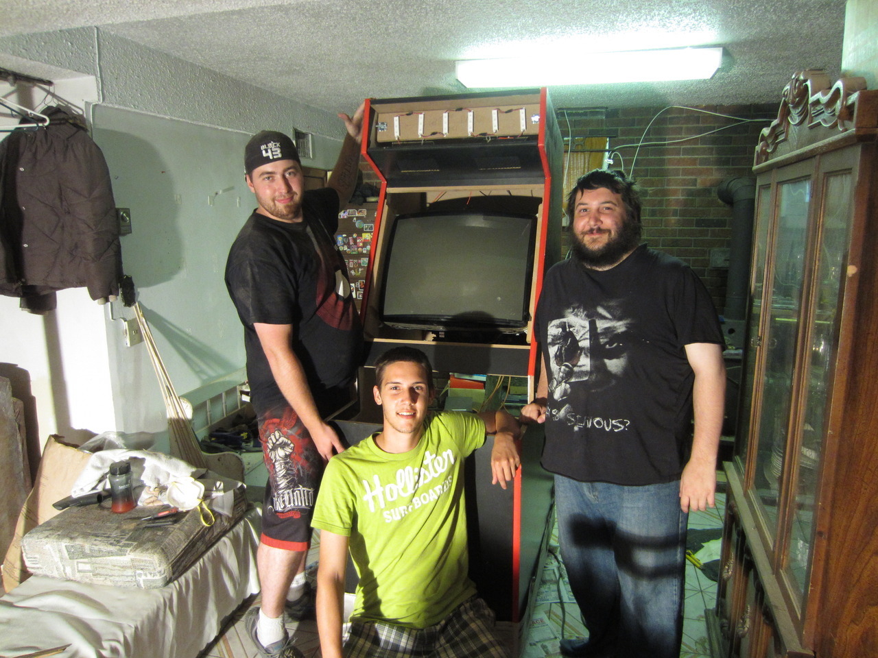
Got the monitor into the cab a few weeks ago, with the help of a friend and my two brothers:


Unfortunately some depth measurements were off... :banghead:  :cry: and we had to take it out for bracket modifications.


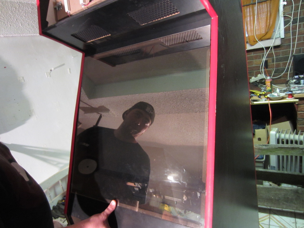
What you are seeing there is the monitor glass, sitting where it should be at the bottom but unable to lie flat up top due to the monitor screen hanging out like a beer belly on a hot July.

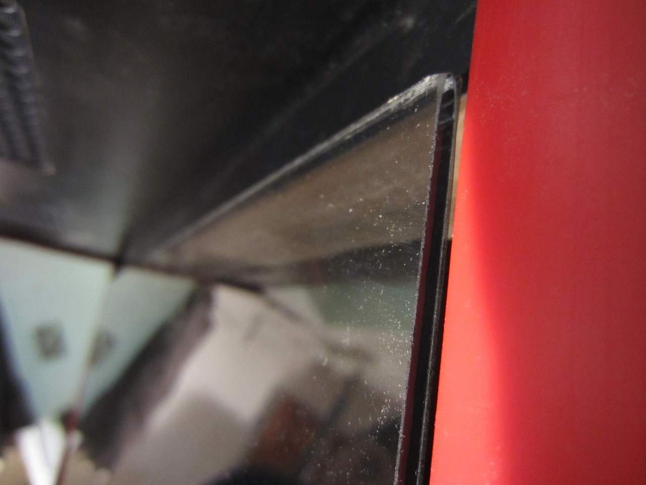
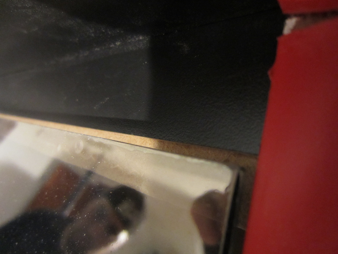
The brackets that the TV is sitting in have been Liquid Nailed into the cab, so they aren't going anywhere.  Our new problem, plain and simple, was how to get this monitor to sit further back in the cab.  We took a couple days to think about the best way to do this while still maintaining cab stability (as has been said time and time again, build around the television, right?)

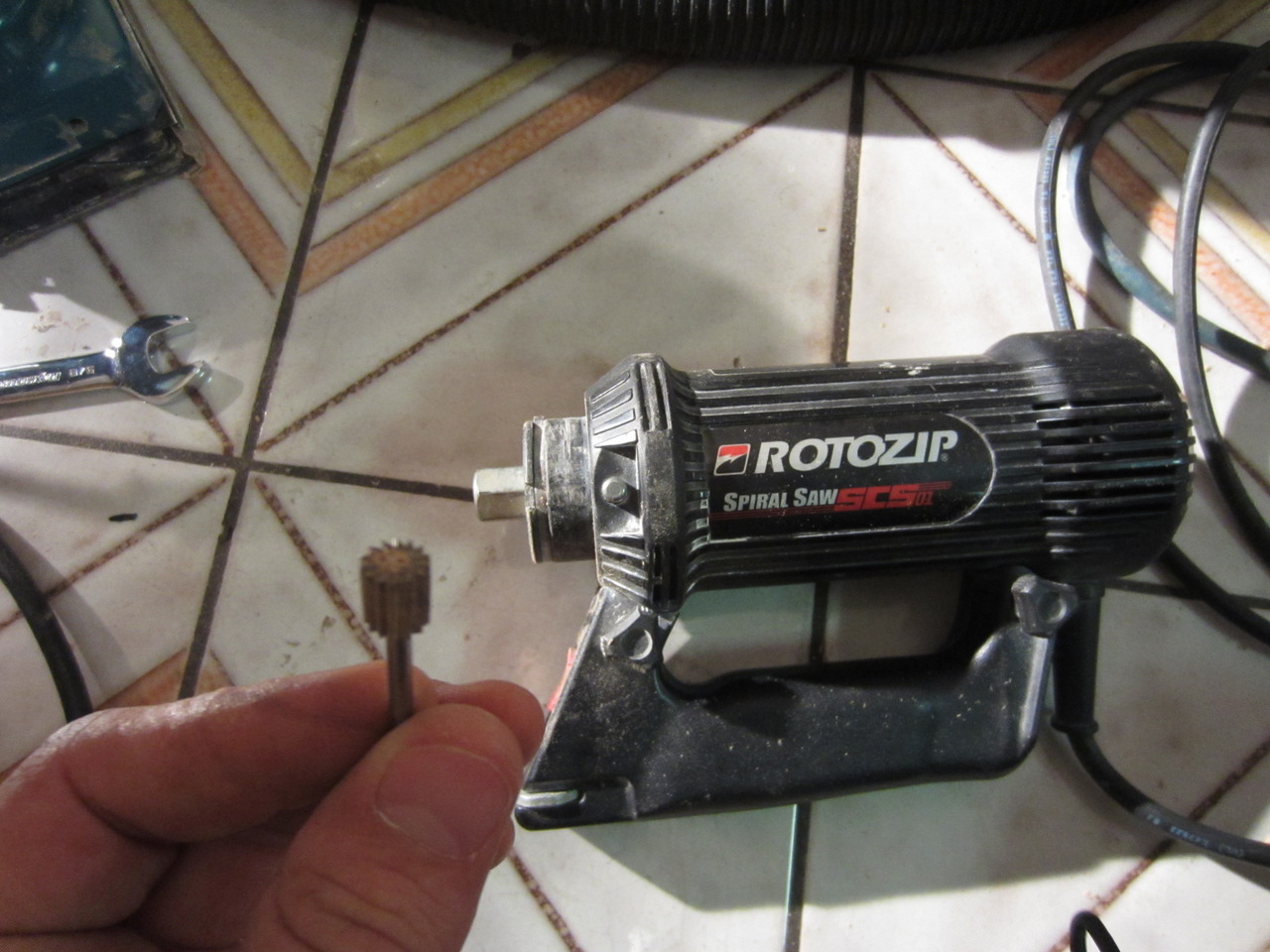
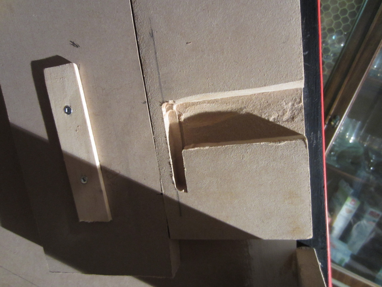
The only solution we could think of was taking a dremel cutting bit and expanding the slots in the brackets back enough to allow the TV to sit further back.  My father-in-law had a RotoZip which is basically a dremel that has an optional guide that can be attached to it for precision cuts:


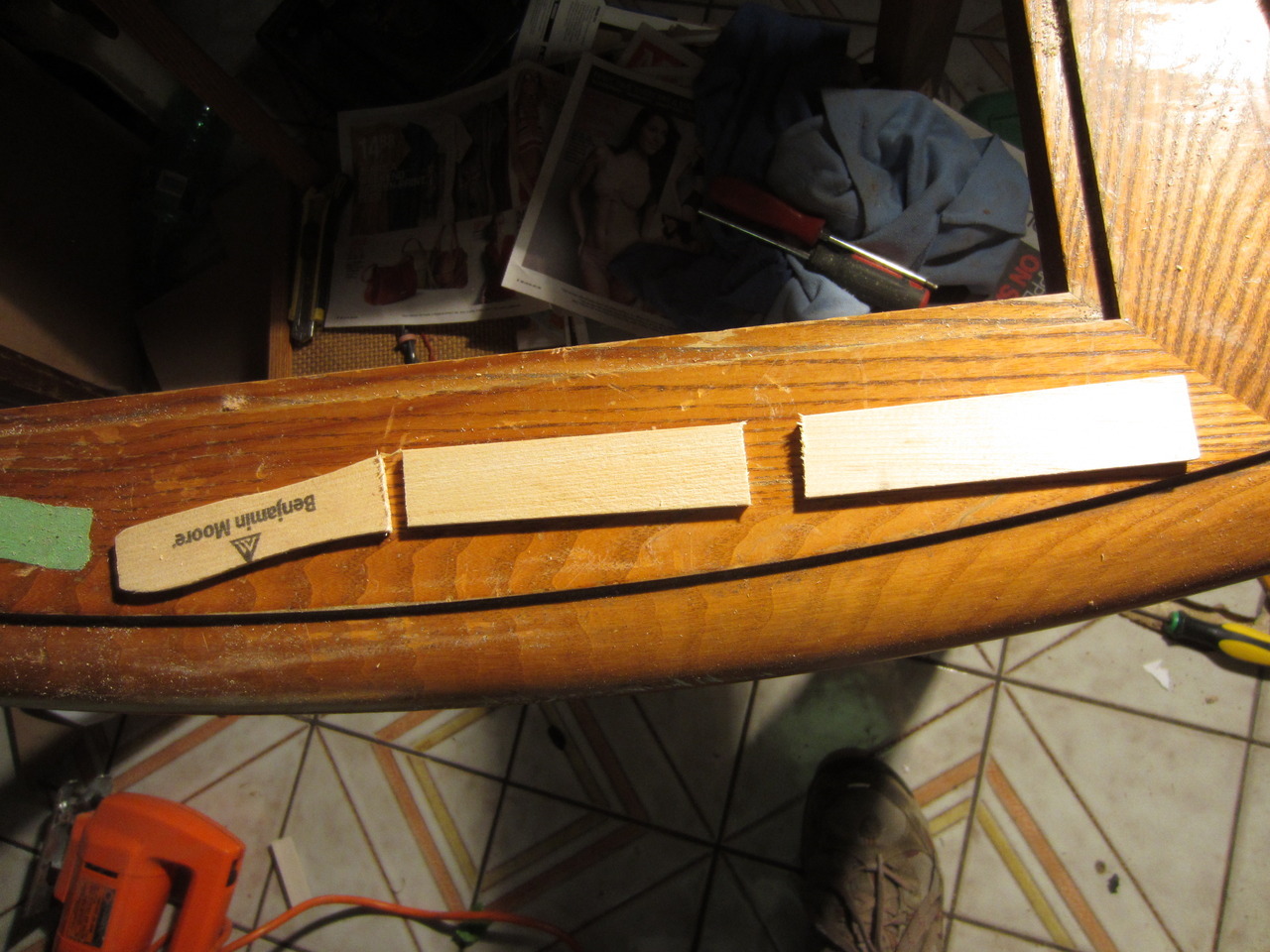
We needed to create a guidepiece for the dremel to run along, so I did the proper measurements on a scrap piece of wood while it was clamped to the bracket:


I then chopped up a paint stir stick to make flat-edged guide pieces:


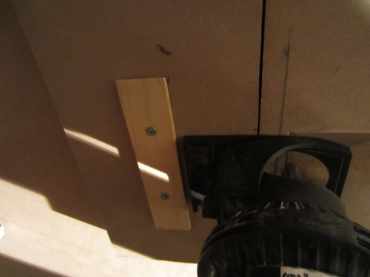
and attached them to the guide piece, lining the flat edge up with the marks I made earlier.  Here's me testing the distance by putting the dremel with the guide attached into the mix... looks good:


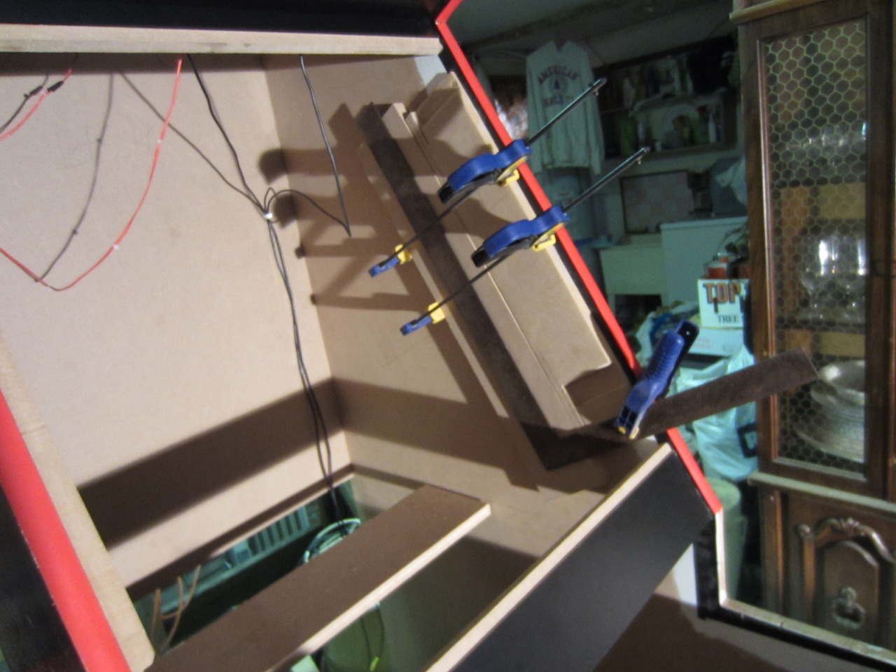
After dremelling the slot back:


Unfortunately, the dremel bit was not "deep" enough to go into the bracket to where it needed to be, so it took two passes (with a pause betwen to remove the bit and re-seat it into the tool so that it sticks out further) to bring it down to where it needed to go.  Double-unfortunately, at one point the button that locks the cylinder on the RotoZip would no longer catch to allow for proper loosening of the bit, so now we have a RotoZip with a bit in it that won't come out.   :banghead:

This is where the project currently sits.  The fiancee and I just bought a house (our first!) and are in the process of renovations before moving in at the end of August, so updates will come at a very slow pace for the next while as we settle in and get our bearings.

SpaceHedgehog

  • Trade Count: (0)
  • Full Member
  • ***
  • Offline Offline
  • Posts: 937
  • Last login:February 06, 2023, 12:10:24 pm
  • Almost done ...
Re: The Smash Pad - Looking for feedback on Artwork
« Reply #116 on: August 25, 2012, 01:12:27 am »
Really enjoyed reading through this - great stuff  :applaud: You can never have too many pictures in my opinion.
Click a pic for a video tour 

Nestafari

  • Trade Count: (0)
  • Full Member
  • ***
  • Offline Offline
  • Posts: 83
  • Last login:August 21, 2019, 09:08:58 am
Re: The Smash Pad - Looking for feedback on Artwork
« Reply #117 on: August 30, 2012, 10:12:12 pm »
Continue !  :applaud:
Space Simpsons cab in progress

Seith

  • Trade Count: (0)
  • Full Member
  • ***
  • Offline Offline
  • Posts: 402
  • Last login:September 08, 2018, 10:50:41 am
Re: The Smash Pad - Looking for feedback on Artwork
« Reply #118 on: November 13, 2012, 04:33:30 pm »
This is where the project currently sits.  The fiancee and I just bought a house (our first!) and are in the process of renovations before moving in at the end of August, so updates will come at a very slow pace for the next while as we settle in and get our bearings.

Yeah... about that....

Just chiming in to let you all know that I am still alive and kicking, renovations have taken much longer than originally expected.  Here we are into November and we're STILL at it (haven't moved in yet, living at the in-laws for the time being).

The Smash Pad has not been touched since mid-August.  It is currently sitting in my Dad's basement.  I have set a goal for myself to have it done and into my new house before the new year.  Come hell or high water, I will try my damnedest to make that happen, although I know that getting it out of my Dad's basement may be the biggest hurdle to overcome, as we would have to go out through the garage which means an old truck need to be removed/winched out first.

I live in Canada, and we're coming into the Winter season.  Wish me luck.

sharpfork

  • Trade Count: (0)
  • Full Member
  • ***
  • Offline Offline
  • Posts: 618
  • Last login:April 07, 2023, 12:43:42 pm
    • KADE
Re: The Smash Pad - The final stretch
« Reply #119 on: November 15, 2012, 11:45:55 am »
Thank you for taking so many pics of the process.  It is looking great!

I hope someone is around to take pics of the move out of the basement.