Thanks byrneaar. I will put in all of those measurements.
Ok so here is what I will focus on talking about today.
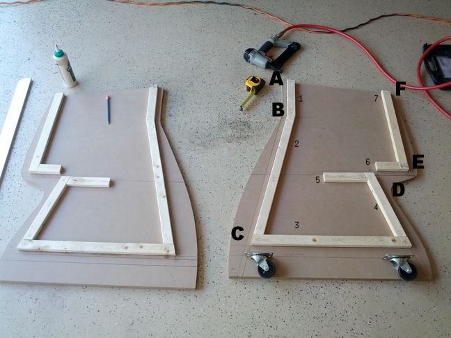
I have numbered each of the furring strips from 1 - 7 starting at the front of the showpiece and moving down and around. To visualize the angles I will use the method that you are standing in front of your miter saw with the blade set at 0° and all angle references will show a (R) if you grab the miter and move it to your right or (L) if you grab the miter saw adjuster and move it left.
1. 8 15/16" on the long side with a 6°(L) angle at the top and 4°(R) angle at furring strip #2
2. 24 1/8" on the long side with a 15.5°(R) angle at furring strip #1 and 15.5° (R) angle at furring strip #3
3. 22 7/16" on the long side with a 15.5°(L) angle at furring strip #2 and 14.5° angle at furring strip #4 (Note: this furring strip spans the bottom with furring strip # 2 and 4 sitting on top of it. This is the furring strip that I put on first. It is placed 4 1/2" from the bottom of the showpiece. I sandwich one 3/4" MDF and one 3/4" PLY wood panels together to form a very solid 1 1/2" base for the casters. I put 3 lines on the showpiece from the bottom. The first at 3", the next at 4 1/2" and the final one at 17" all measured from the bottom of the showpiece. I will detail the base plate and casters later.
4. 11 3/8" on the long side with a 14.5°(L) angle at furring strip #3 and 14.5°(L) angle at furring strip # 5
5. 6 1/2" on the long side with a 14.5°(R) angle at furring strip #4 and 0° angle on the left side looking at the reference image
6. 3 1/2" long with a 0°angle on the left side looking at the reference image and 1°(R) at furring strip # 7
7. 17 9/16" on the long side with a 6°(R) angle at the top and 1°(L) angle at furring strip #6.
Just reverse each of the angles for the other side or you can do what I did and just cut one and use it as a template and cut an identical furring strip and flip it over to use on the other panel.
A - 3/4"
B - 15/16"
C - 3 1/16" from the front edge following the 4 1/2" line
D - 1" from the deepest part of the curve to the edge of the furring strip as it goes up to meet the 17" line measured parallel to the 17" line
E - 1 1/16" following the 17" line from the edge
F - 3/4"
A and F should meet the front and back edge to create a flat area that will be used for attaching the wooden dowel. The other areas are not as important but they need to be in the general area of these measurements. The really important measurements are more the 3", 4.5" and 17" line. Even the furring strip angles can be manipulated 1- 2°'s as necessary.
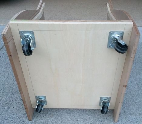
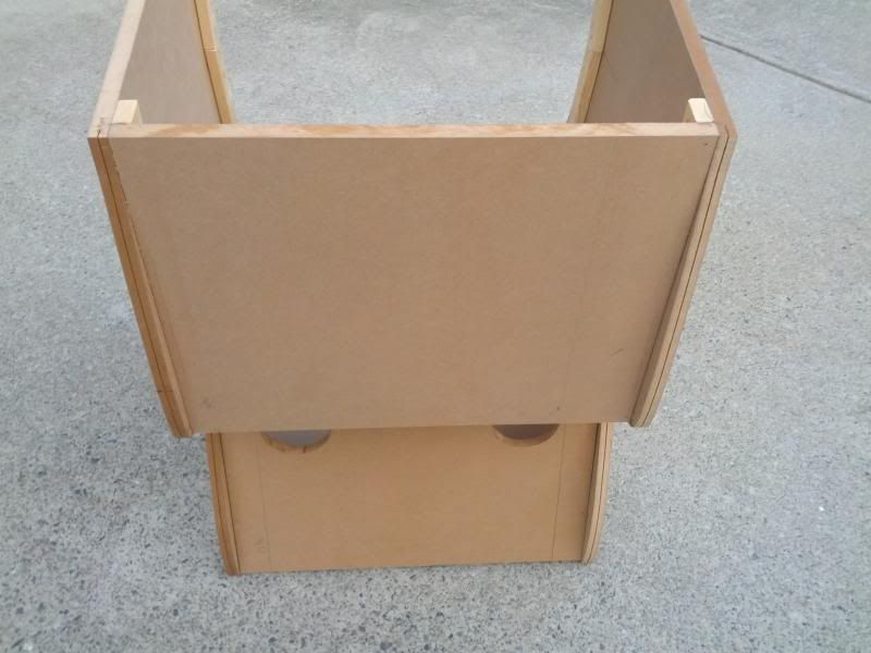
Here is the sandwiched 3/4" MDF and 3/4" PLY wood base plate. This plate is 26" Long and 23" wide. The casters are all place 1 1/2" from the side which you can see in the reference image above.
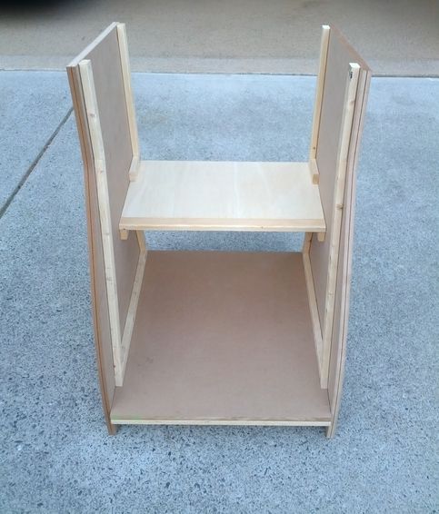
The Nighthawk shelf serves as the bottom of the exterior of the case as well as the internal shelf with a decorative 1 1/2" furring strip at the interior edge to ensure the wires flow smoothly over with no snagging. This shelf is 12" deep and 23" wide. If you choose not to use the decorative furring strip then you would increase the shelf size by 1 1/2" to 13 1/2" x 23".
The back bottom panel is 17 3/16" with a 14.5° angle at the bottom and no angle at the top where it hits the Ply wood. You could add this angle if you want but I didn't. The goal is to get this thing air tight and I like to use the gap for caulk on the inside to aid my goal of air tightness.
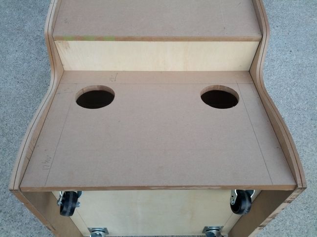
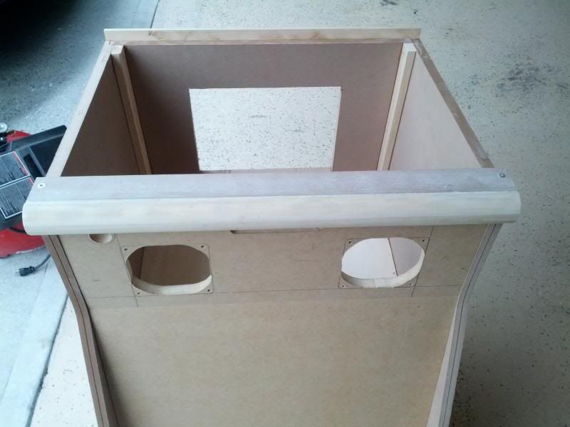
The real machine uses this panel for speakers but since I am using the TV as my speakers I take the opportunity to use these holes for a filtered air intake. I got 4 of these RFT-120 120mm Fan Filter covers from Newegg:

I start by measuring 2 3/4" from the top of the panel and marking that as the top line then measure 2" from the left and right side of the panel. I removed the filter and place the fan filter cover with circular insert on the top and side lines and used a pencil to mark a rough circle in the 2nd circle from the edge. Pressing on the interior circular part while removing the outer cover allows me to keep it positioned and continue to really mark the circle so I could use a jig saw and cut them out. I then used a drill to pre-drill all of the screw holes because after I paint this thing I won't be able to see the top and side lines.
The back top panel is 18 2/16" on the long side and 18" on the short side after a 6° angle cut at the top. The top angle gives a nice flat surface that the CP will sit on top of.
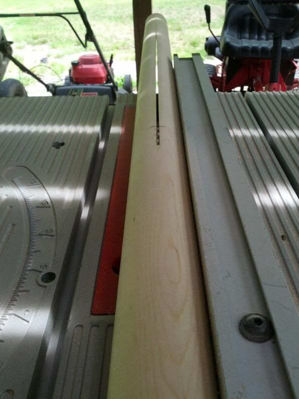
Ripping the 2" dowel on the table saw. You can see the mark for 24 1/2 " that I rip past. They sell this dowel at HD in the wood molding area.
And finally, here is the finished front. I will put up the measurements later as I forgot my notes from this weekends progress. You can see the routed slot handle, soft power button and two 120 mm fan cut-outs. This showpiece, like the last one, pulls air in through filtered fan covers where the speakers normally go and exhausts the warm internal air out the top. This is a very effective way to keep the computer inside cool and clean. The nighthawk box has a filtered air intake too and so these things are really hard pressed to get any dust inside the computer.


 Home
Home Help
Help Search
 Login
Login Register

 Send this topic
 Print
Print Topic: jikkjack's golden tee unplugged showpiece cab build (Read 79858 times)


