Thanks for the compliments guys... I'm proud to see it well received.
Here's some photos that should hopefully address the 'how' questions:
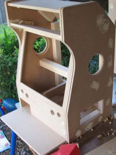
HOW is the CP secured?The floor of the cabinet extends out to the front and forms the floor of the CPs. The CP side and front walls sit 'around' that floor (the rear wall of the CP is 12mm (1/2") which is the height of that floor panel). I did toy with magnet latches, velcro, plugs etc but none of it was necessary as it doesn't budge... the only way you can move the CP is to lift it straight up.
 HOW did you get that admin panel so neat?
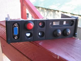
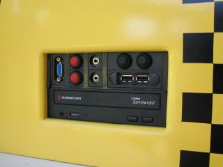
I purchased a FrontEx kit for approx US$10 that is designed for modular mounting of ports on the front of PCs. Since I designed the admin panel to take two standard 'PC drive bay' devices it was perfect. I asked for empty bezels and added/wired my own ports and plugs. The USB took a bit of hacking (as the ports were closer together on the USB cable I had)
 What method is used to connect the CPs?
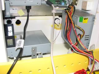
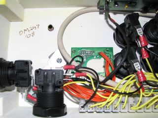
If you look at the pictures above you can see a little alcove on the front of the cabinet. In there is a USB extension cable and a female 15pin connector (a VGA plug) which goes to the IPAC. The CPs components are wired to a terminal block and then to a (male) VGA plug.
On the side of the cabinet (on the admin panel) you'll see another VGA plug. This is the same thing but wired to the 2player side of the IPAC. This way, you can use exactly the same control panel and plug it either into the front (1 player) or the side (2 player) or if you have multiple control panels, 1 & 2 player simultaneously. The beauty of them being on extendable cables is you can pull them out to sit further away from the cabinet and have two control panels side by side (they can free stand and not just be wedged to the cabinet).
How is it put together?You'll be sorry you asked:
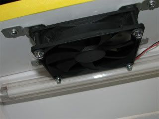
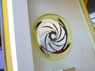
The exhaust fan (upper rear angled panel)
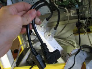
Specially shortened power leads
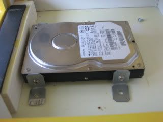
The HDD secured to the floor of the cabinet
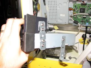
The admin panel secured to the CD-ROM which is secured to the floor (I love that bendable bracing stuff)
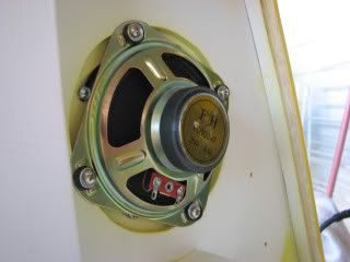
Speaker and 'fan grill' attached:
Power supply is held to the wall using 'shelf angle brackets' which are drilled into the case of the fan (be careful with this, remove the lid of the P/S and ensure the screws dont go anywhere near internal components)
The LCD (which you can JUST make out in some of the photos above) is sandwiched to the front bezel using HDD mounting brackets ($3). You can use virtually anything you like, but I found these metal brackets had long holes so I could adjust the tension depending where I tightened the screws. The bezel itself is a 6mm (1/4" ?) round routed edge on the front, and has a 6mm recess on the rear. A 6mm piece if smoked glass is put in that recess then the de-cased LCD is put behind the glass. The finished product looks superb as the tint makes the screen contrast perfect.
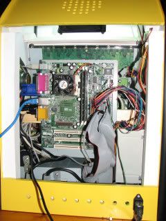
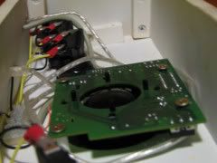
The mounted system board(s)
The original (which turned out to be too slow)
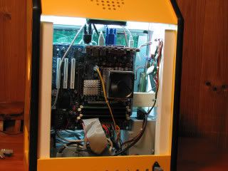
The P4 2.66ghz (kicks ass). Note I've changed the orientation of the system board to be vertical (the board was larger and I needed room for the cables), which meant I had to re-do the length of the audio cables (grr). I also had to change and re-mount the power supply as the old (P3) power supply wouldn't run this board.
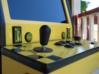
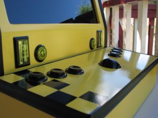
The admin panel (from left: player 2 connection, LCD power, PC power, Microphone in (karaoke), audio out/headphones, volume down, volume up, USB out).
Control panel 1 (8-way 6 button with pinball controls, spinner and micro optical trackball)
Control panel 2 (left/right handed 3-button 2.25" trackball)


 Home
Home Help
Help Search
 Login
Login Register

 Send this topic
 Print
Print Topic: The TAXI CAB (Project Documentation now available in PDF!) (Read 30171 times)


