Ive finished my LED balltops so I thought I would do a little write up/guide for anyone else wishing to do something similar.
Items needed:Modified joystick shaft (see below)
Clear/ Coloured translucent Ball top (lizardlick.com, arcadeshop.de)
LED
Resitor
Solder
Fairly small gauge wire
Small diameter heat shrink
Tools needed:Soldering Iron
Small flat heat screwdriver
Wirecutter/Stripper
File/Dremel
Safety Glasses/Goggles
I did this mod to my Sanwa JLWs but you should be able to apply it to most other joysticks that you can screw the top off.
1) DissasemblyOn the bottom of my JLWs (same for the JLFs) there is an e-clip holding the whole shaft assembly together. Use a small flathead screwdriver to prise this off. Be carefull when you do this as the little buggers have a habit of flying off somewhere. I would advise 'aiming' the e-clip into a towel or something to minimise the risk of losing it. Once it is removed put it to one side and take note of how any other components came out. Also be carefull of any parts under compression from the spring flying out.
You should then be able to remove the shaft from the joystick base. Remove the ball top etc from the shaft.
2) MachiningYou now need to make a hole in the middle of the shaft for the wires to pass though. It depends on the stick you are modding but for the Sanwas I would recommend drilling a hole no larger than 3mm (1/8"). The thread on the Sanwas is 6mm x 1mm pitch which means the root diamater and under cut is roughly 4.7mm. If you go much bigger than 3mm you are not going to leave much strength in the shaft.
Idealy it would be best to drill the hole on a lathe but you could get away with it on milling machine/jig borer etc or possibly even a decent pillar drill if you can hold the job securely and position the drill acurratly. Any decent metal shop/ college etc should be able to do this for you. You could always ask them to make you some shafts from scratch if you wish. (If you want dimensions of the shafts etc let me know)
Hopefully once complete you should have a hole big enough to fit two gauge wires (with a little room to spare) though the hole, kind of similar to this:
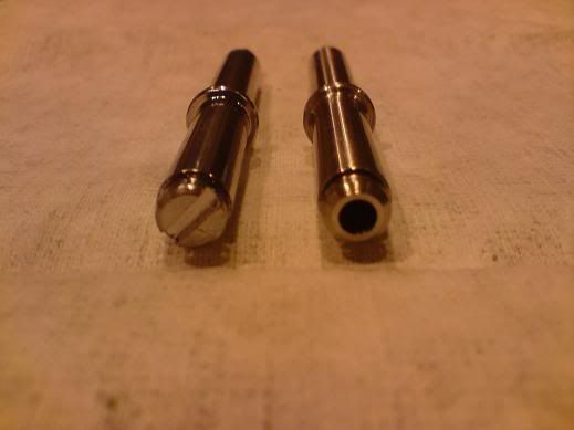
The one on the left is an original one, the one on the right is one I made. There is a flat on the botton but I dont really see any need for it. All I can think its for is to hold with a screwdriver whilst you screw the top on but you can do the same thing with a pair of pliers on the shaft (using a cloth etc to make sure you dont mark it.)
Now you have done that you can prepare the LED to light the ball top.
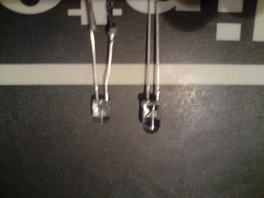
3) LED PrepI used 5mm blue Superbright (13000mcd) LEDs for my joys. The internal bore of the ball tops is 5.1mm, this means the LEDs fit nicely inside the bore up to the point of where the shoulder is on the LEDs and you will find that they foul at the entrance to the bore. You need to remove the shoulder from the LED. I used a fine file but you could use a dremel or similar, just be careful and for gods sake dont hold it in your hand if you are using a dremel!
You will also need to remove some of the plastic of the LED to reduce the 'height' of it. This will allow the LED to fit further inside the ball which will give the threads of the shaft more to grab on to and will also light the ball better. Use any method you like to remove material from the top of the LED, leaving about 1mm between the new top of the LED and the annode/cathode inside. I used a bench grinder for speed/ease.
You should end up with something similar to the LED on the right:
 4.Soldering
Once you have done this, trim the legs of the LED down (noting which is the annode/cathode) and solder two small gauge wires to the legs. You then need to cover the solder joins and the whole of the exposed legs with heat shrink. Make sure you use as small heat shrink as possible and also make sure your solder joints are as small diameter as possible otherwise you may have trouble fitting it inside your drilled shaft. You should be looking to end up with something like this:
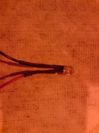
Now thread your wires though the shaft and try to get the whole heat shrunk section inside the shaft. Mine took a little persuasion but eventually I ended up with this:
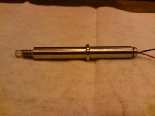
You now need to attach a resistor to the negative annode of the wire atatche to the LED. My LEDs were rated at 3.2v-3.4v so I used a 100Ohm resistor. Cut the negative wire off protruding from the bottom of the shaft leaving around 1" or so. Strip the wire and solder your resistor to the wire and then solder another wire to the other side of the resistor.
4)Reassemble and testReassemble your joystick, once again taking care with the e-clip.
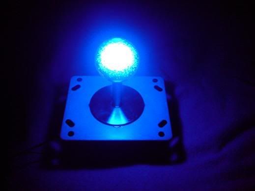
You should now be able to connect your new LED ball top to your power supply! In my case it was the red/black 5v wires from a PC PSU.
Hopefully when you turn the power on you should end up with something like this!:
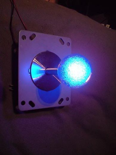
(/\ With the light on)
(/\ With the light off)
Job done! Give your self a pat on the back and pour youself a cold one

I know I probably went into too much detail but I wanted to make this as noob friendly as possible. I am almost as noob as you can get with electronics so if I can do this anyone can!
Good luck!


 Home
Home Help
Help Search
 Login
Login Register

 Send this topic
 Print
Print Topic: Guide to: DIY LED Joysticks (Read 25506 times)


