So if I get my power from a USB cable, I'd put the red 5V wire before the led, and then just ignore the black wire?
Tie the USB ground wire to the same ground you're using for the encoder.
- Don't assume that wire colors indicate their function. Best practice is to
always verify with a multimeter.
This is going to be in an old DB9 joystick for using with old Ataris/8-bits/Amigas, and I really don't want to damage the vintage hardware!
This crucial detail might change things a bit.

At first glance, the good news is that computers from that era typically used 5v logic levels, not 3.3v like many newer consoles.
The bad news is that some of these systems might use "active high" inputs (5v triggers the input instead of ground) so you'd end up tying the retro system 5v directly to USB ground.

To be safe, you'd need to check the system schematics and component datasheets for each system's inputs, and it wouldn't hurt to also confirm with a multimeter.
For example:
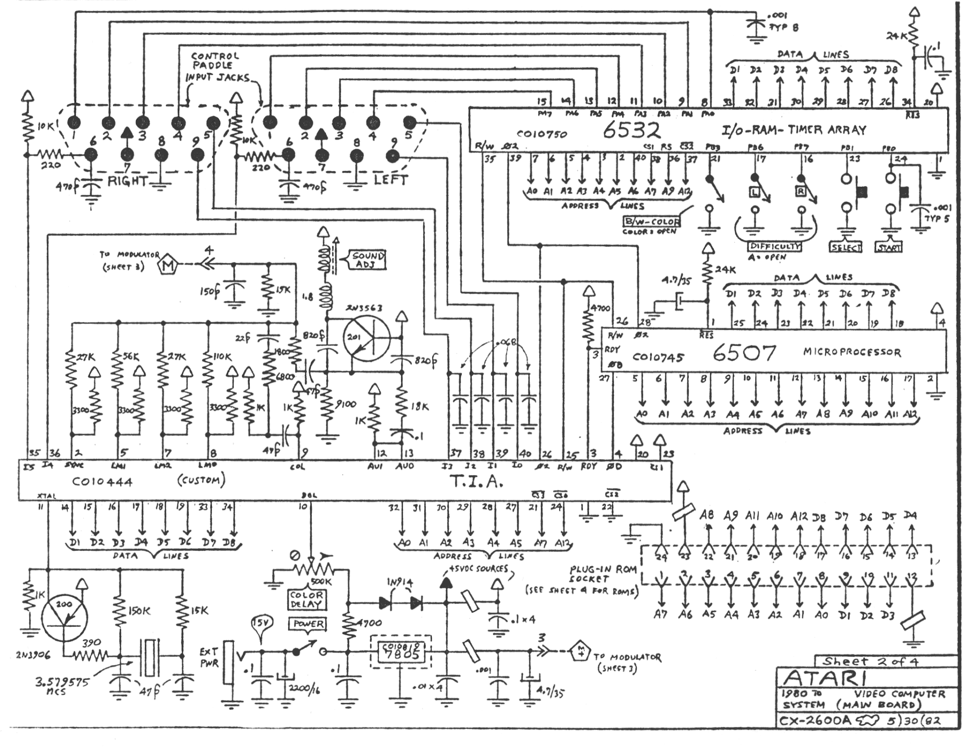
- The common on the Atari joystick is pin 8 of the DB9. (upper left of the schematic
here)
- Pin 8 of the DB9 on the Atari CX2600A is tied to ground. (upper left of the schematic below) That confirms that the Atari CX2600A is an active low device.
- Pins 1-4 (joystick U/D/L/R) on the Atari CX2600A DB9 go to the
6532 RAM-I/O-Timer chip. The 3rd page of the zipped datasheet
here confirms that the operating voltage (VCC) and input voltages (V
IN) can handle 5v.
- The CX2600A schematic confirms that pin 20 of the 6532 (upper right) is connected to 5v (lower center). The connection is shown by the hollow triangle labeled "+5VDC sources" in the power section -- every hollow triangle on the schematic like pin 20 of the 6532 is a 5v power line.
No sense in researching systems you won't be using so
exactly which systems you want to use this mod with?
- Atari 2600/5200/7800 consoles?
- Atari 400/800/XL/XE computers?
- Amiga 500/1000 computers?
You should be able to use a battery pack for power instead of USB.
You can put the whole mod (battery pack, LED, current limiting resistor, and a DB9 extension/feedthru cable) in a project box to make the setup more neat, self-contained, and easy to position for video capture.

- Using a project box on a DB9 extension/feedthru cable will save the effort of modding that old joystick and allow you to use other sticks if desired.
Scott


 Home
Home Help
Help Search
 Login
Login Register

 Send this topic
 Print
Print Topic: Help with basic electronic circuit (Read 2702 times)


