Main Restorations Software Audio/Jukebox/MP3 Everything Else Buy/Sell/Trade
Project Announcements Monitor/Video GroovyMAME Merit/JVL Touchscreen Meet Up Retail Vendors
Driving & Racing Woodworking Software Support Forums Consoles Project Arcade Reviews
Automated Projects Artwork Frontend Support Forums Pinball Forum Discussion Old Boards
Raspberry Pi & Dev Board controls.dat Linux Miscellaneous Arcade Wiki Discussion Old Archives
Lightguns Arcade1Up Try the site in https mode Site News

Unread posts | New Replies | Recent posts | Rules | Chatroom | Wiki | File Repository | RSS | Submit news


Author Topic: Wiring a rocker switch for aimtrak recoil  (Read 4043 times)

0 Members and 1 Guest are viewing this topic.

bubba1212

  • Trade Count: (0)
  • Full Member
  • ***
  • Offline Offline
  • Posts: 18
  • Last login:October 11, 2023, 11:54:28 am
  • I want to build my own arcade controls!
Wiring a rocker switch for aimtrak recoil
« on: November 05, 2021, 11:00:05 am »
I saw this YouTube video where the guy wired a rocker switch to the power for his aimtrak recoil. I love this idea as sometimes the recoil is annoying for some games but I want it for others. I asked the owner how he did it but no response. I’m an amateur when it comes to wiring but can follow step by step instructions. If anyone has done something similar I’d love to see it.

Titchgamer

  • Trade Count: (0)
  • Full Member
  • ***
  • Offline Offline
  • Posts: 4222
  • Last login:December 17, 2023, 08:05:48 am
  • I have a gaming addiction.....
Re: Wiring a rocker switch for aimtrak recoil
« Reply #1 on: November 05, 2021, 12:24:29 pm »
You would just need to wire the switch in series with the solenoid to break the circuit.
Very easy to do.

PL1

  • Global Moderator
  • Trade Count: (+1)
  • Full Member
  • *****
  • Offline Offline
  • Posts: 9399
  • Last login:Today at 05:32:12 am
  • Designated spam hunter
Re: Wiring a rocker switch for aimtrak recoil
« Reply #2 on: November 05, 2021, 12:50:41 pm »
If anyone has done something similar I’d love to see it.
What you want to do is similar to wiring the 3-tab rocker switch in a fused IEC power inlet.
- It's a different application, but basicly the same idea.
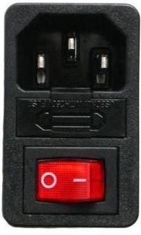
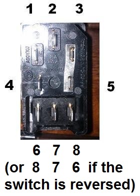
 

Recoil power "+" (24v?) comes in on tab 8.

When the switch is in the "on" (closed) position recoil power is applied to the current-limiting resistor + lamp and it goes out on tab 7 to the gun.

The possible difference for your setup is what you have connected to tab 6.
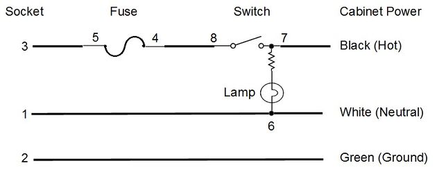


If you have a 24v recoil power supply and get a switch/lamp rated for 24v, daisy-chain recoil power "-" to tab 6 -- same as "Neutral" above.

If you have a 24v recoil power supply and get a switch/lamp rated for 12v like this one, you'll need to add another current-limiting resistor between tab 6 and the recoil power "-" daisy-chain.

To calculate the value of that 2nd resistor, use an LED calculator like this one.
- Power supply voltage (V): 24
- LED voltage drop (V): 12 (this is the voltage drop across the LED and current-limiting resistor inside the switch)
- LED current rating (mA): 20 (If the LED is too bright, you can reduce this to 15mA or less)
- Number of LEDs: 1

When you enter those values, you get a 620 ohm, 1/4 watt resistor.  (15mA ==> 820 ohm)
- In this diagram, you would install it between the brass tab (tab 6) and the red wire.
- When you wire your cab, you should use standard wire colors -- red for DC+ and black for DC-.   ;D


Scott
« Last Edit: November 05, 2021, 01:09:15 pm by PL1 »