Main Restorations Software Audio/Jukebox/MP3 Everything Else Buy/Sell/Trade
Project Announcements Monitor/Video GroovyMAME Merit/JVL Touchscreen Meet Up Retail Vendors
Driving & Racing Woodworking Software Support Forums Consoles Project Arcade Reviews
Automated Projects Artwork Frontend Support Forums Pinball Forum Discussion Old Boards
Raspberry Pi & Dev Board controls.dat Linux Miscellaneous Arcade Wiki Discussion Old Archives
Lightguns Arcade1Up Try the site in https mode Site News

Unread posts | New Replies | Recent posts | Rules | Chatroom | Wiki | File Repository | RSS | Submit news


Author Topic: Build your own HID-mouse compatible spinner  (Read 9886 times)

0 Members and 1 Guest are viewing this topic.

Marsupial

  • Trade Count: (0)
  • Full Member
  • ***
  • Offline Offline
  • Posts: 511
  • Last login:Yesterday at 09:00:56 pm
  • I am teh Mars!
Build your own HID-mouse compatible spinner
« on: April 30, 2021, 08:57:32 am »
After searching quite some time online I found out there aren't much DIY options for spinners.

Some people revitalize vintage spinners with controllers similar to what we do for trackballs - either commercial ones or old-style ball-mouse hack (those tends to become scarcer and scarcer...)

Now, there are commercial spinners available, but part of doing it yourself is to have more flexibility and reduced costs at the expanse of more work on your part.

The commercial spinners available nowadays are great. They reduced the spinner footprint considerably while keeping great resolution. They have nice options and are easy to install.
Some of them use commercial-grade optical rotary encoders.


Now...

Thosed encoders are available to anyone, including home arcade builders. I got a couple off the bay for about 12$ each.

At first I wanted to control them using an ball mouse, but this didn't work. I think the resolution is far too fast for the old mice I had.

So I got an Arduino Pro Micro and made my own.

The code is super easy. Here it is without buttons - adding buttons would only need one added library (keyboard)
NOTE: you need to install the encoder.h library in arduino...

Code: [Select]
#include <Encoder.h>
#include <Mouse.h>

Encoder spinner0(0, 1);
Encoder spinner1(2, 3);


void setup()
{
  Mouse.begin();
}

long oldSpinner1Pos  = 0;
long spinner1Delta = 0;
long oldSpinner0Pos  = 0;
long spinner0Delta = 0;

void loop()
{

  long newSpinner0Pos = spinner0.read();
  long newSpinner1Pos = spinner1.read();

  if (newSpinner0Pos != oldSpinner0Pos)
  {
    spinner0Delta = oldSpinner0Pos - newSpinner0Pos;
    oldSpinner0Pos = newSpinner0Pos;
  }

  if (newSpinner1Pos != oldSpinner1Pos)
  {
    spinner1Delta = oldSpinner1Pos - newSpinner1Pos;
    oldSpinner1Pos = newSpinner1Pos;
  }

  Mouse.move(spinner0Delta, spinner1Delta);

  spinner0Delta = 0;
  spinner1Delta = 0;
}

once programmed on the chip, using the proper pins, windows will recognize the device as a HID mouse; the two spinners acts like the 2 axis of the mouse- similar to an etch-a-sketch! (run paintbrush and you got a game going!)

Ok, mounting it on a control panel isn't as easy as some commercial spinners, but reactiveness is awesome.
The spin duration will depend on the knob used. Sadly on the encoders I got there's no room for added weight, but I can live with that.

The whole thing (two spinners) costed me less than 40$.
« Last Edit: April 30, 2021, 09:00:01 am by Marsupial »
-Mars

PL1

  • Global Moderator
  • Trade Count: (+1)
  • Full Member
  • *****
  • Offline Offline
  • Posts: 9401
  • Last login:Today at 06:46:32 am
  • Designated spam hunter
Re: Build your own HID-mouse compatible spinner
« Reply #1 on: April 30, 2021, 06:03:59 pm »
At first I wanted to control them using an ball mouse, but this didn't work. I think the resolution is far too fast for the old mice I had.
Yes, the encoder wheel resolution was far lower (less pulses per revolution) and the sample rate for the old optical (mouse) encoder is too slow to keep up with every phase step in the quadrature waveform output from these new rotary encoders, causing backspin.
- For anyone interested, there's some technical info explaining backspin in this post.


Code: [Select]
Encoder spinner0(0, 1);
Encoder spinner1(2, 3);
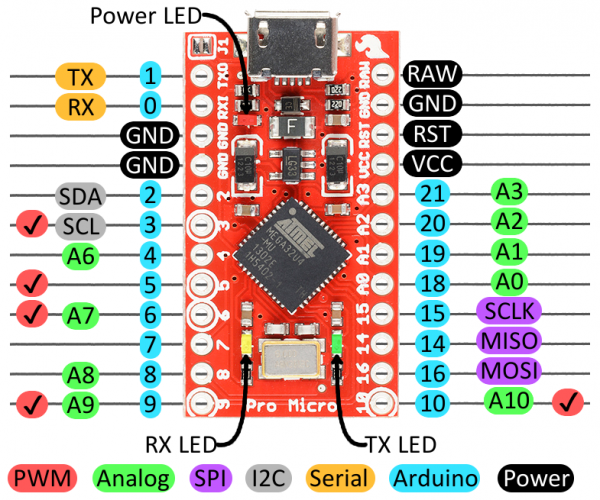
For those trying to figure out how to wire the rotary encoder to the Pro Micro, these two lines of Marsupial's code define which Arduino pin numbers (blue circles) are the data lines.
- Spinner0 uses Arduino pins 0 and 1.
- Spinner1 uses Arduino pins 2 and 3.
- If a spinner is going in the opposite direction expected, swap the data lines for that spinner. (0<=>1 for Spinner0 or 2<=>3 for Spinner1)

The other spinner connections are 5v (VCC) and ground.
- Be very careful to not accidently connect a data line to 5v (VCC) because that will instantly destroy the data line circuit on this type of encoder.   :scared


Ok, mounting it on a control panel isn't as easy as some commercial spinners
If you want to 3d print a mount, the M3 screw holes are 120 degrees apart with one set of three 14mm from the center of the shaft and the other set at 15mm.

This post has a Thingiverse link to one rotary encoder mount bracket and OpenSCAD code for another bracket that can be modified for use on a control panel.
- LMK if anyone is interested in a control panel mount.   :cheers:
http://forum.arcadecontrols.com/index.php/topic,159527.msg1677612.html#msg1677612


Scott

Marsupial

  • Trade Count: (0)
  • Full Member
  • ***
  • Offline Offline
  • Posts: 511
  • Last login:Yesterday at 09:00:56 pm
  • I am teh Mars!
Re: Build your own HID-mouse compatible spinner
« Reply #2 on: April 30, 2021, 08:31:01 pm »
Thanks Scott.

I didn't get too technical at first, but you summed it up very well!

Thanks for posting a nice mount. I'm hoping this helps people out. Spinners are much fun.


On my end, I routed the underneath and have a snug hole, will add a few bolts and call it a day. It's in fact easier than mounting a trackball without the metal mounting plate.

Cheers!
-Mars

PL1

  • Global Moderator
  • Trade Count: (+1)
  • Full Member
  • *****
  • Offline Offline
  • Posts: 9401
  • Last login:Today at 06:46:32 am
  • Designated spam hunter
Re: Build your own HID-mouse compatible spinner
« Reply #3 on: April 30, 2021, 09:29:10 pm »
Thanks for posting a nice mount.
Those mounts aren't what I would call user-friendly for a spinner setup since the other thread was about a 360 degree steering wheel setup.

What would be user-friendly is a 2-piece mount (nut and mount-plate/bezel/threaded-body) similar to the one that StefanBurger made for this trackball.


I've done other parametric 3d models that use a thread library to make a nut and hollow threaded body so it will be fairly easy to add a bezel/mount plate and adjust some variable values, assuming anyone is interested.   ;D


Scott
« Last Edit: April 30, 2021, 09:30:42 pm by PL1 »

Marsupial

  • Trade Count: (0)
  • Full Member
  • ***
  • Offline Offline
  • Posts: 511
  • Last login:Yesterday at 09:00:56 pm
  • I am teh Mars!
Re: Build your own HID-mouse compatible spinner
« Reply #4 on: May 01, 2021, 09:28:25 am »
Honestly, Scott, if I wouldn't already had routed my panel for the encoders, I'd be all about getting a mount, ideally in a hole size I already have.

That said, I surely hope this thread help others in the future...
« Last Edit: May 01, 2021, 10:23:55 pm by Marsupial »
-Mars

PL1

  • Global Moderator
  • Trade Count: (+1)
  • Full Member
  • *****
  • Offline Offline
  • Posts: 9401
  • Last login:Today at 06:46:32 am
  • Designated spam hunter
Re: Build your own HID-mouse compatible spinner
« Reply #5 on: May 03, 2021, 03:13:46 pm »
I'd be all about getting a mount, ideally in a hole size I already have.
Something like this for a 2"/50mm hole saw?

Anyone have a preference for a chamfered one like this (very easy to code) vs. one with a roundover? (slightly harder to code and takes longer to render, but doable)


Here's the initial updated version OpenSCAD code.
- Haven't done a test print, but it should and it does work on a 3/4" control panel.  Print the mount face down.
- Install the mount and nut, then the encoder and screws, then the knob.
- If you want to adjust any parameters, the variables are on lines 52-67.
-- If the threaded part is too tall and hits the cable, adjust "ThreadedRodHeight" on line 54.
-- If you want countersunk screw holes, change "ScrewHoleTop" on line 61.

Code: [Select]
// Rotary encoder mount and nut created using thread library found at https://www.thingiverse.com/thing:31363

// Metric Screw Thread Library
// by Maximilian Karl <karlma@in.tum.de> (2012)
//
//
// only use module thread(P,D,h,step)
// with the parameters:
// P    - screw thread pitch
// D    - screw thread major diameter
// h    - screw thread height
// step - step size in degree
//

module screwthread_triangle(P) {
difference() {
translate([-sqrt(3)/3*P+sqrt(3)/2*P/8,0,0])
rotate([90,0,0])
cylinder(r=sqrt(3)/3*P,h=0.00001,$fn=3,center=true);

translate([0,-P/2,-P/2])
cube([P,P,P]);
}
}

module screwthread_onerotation(P,D_maj,step) {
H = sqrt(3)/2*P;
D_min = D_maj - 5*sqrt(3)/8*P;

for(i=[0:step:360-step])
hull()
for(j = [0,step])
rotate([0,0,(i+j)])
translate([D_maj/2,0,(i+j)/360*P])
screwthread_triangle(P);

translate([0,0,P/2])
cylinder(r=D_min/2,h=2*P,$fn=360/step,center=true);
}

module thread(P,D,h,step) {
for(i=[0:h/P])
translate([0,0,i*P])
screwthread_onerotation(P,D,step);
}
//
////////////////////////////////////////////
//
// Variables:
//
////////////////////////////////////////////
ThreadPitch = 1;          // Screw thread pitch
ThreadMajorDiameter = 49; // Screw thread major diameter
ThreadedRodHeight = 23.8; // Threaded rod height
ThreadStep = 2;           // Thread step size in degrees
PlateThick = 2.4;         // Mount plate/bezel thickness
BezelTopDia = 50;         // Bezel top diameter
BezelBottomDia = 55;      // Bezel bottom diameter
BezelCenterHole = 21;     // Bezel center hole
ScrewHoleBottom = 3.45;   // Bottom of screw hole diameter
ScrewHoleTop = 3.45;      // Top of screw hole diameter, for non-countersunk screws use same value as ScrewHoleBottom
ScrewDistance = 15;       // Distance from center of shaft to center of screw hole, usually 14 or 15
CenterCylinder = 40;      // Center cylinder diameter
NutDiameter = 64;         // Nut diameter (point-to-point)
NutThickness = 4;         // Nut thickness
WiggleRoom = 1.02;        // Scale multiplier for threaded rod X-axis and Y-axis that allows nut to turn easier
NutOffsetX = 70;          // X-axis offset distance of nut
//
// Number of fragments (polygon sides) used to render a full circle.
    $fn = 180; // Default = 180  Typical range = 6 - 360
    // 6 will render a circular hole as a hexagon, 8 will render a circular hole as an octagon.
    // Lower the number for faster rendering, raise the number for smoother rendering.
//
////////////////////////////////////////////
//
// Make the part:
//
////////////////////////////////////////////

// Mount
    // Bezel/mount plate minus screw holes and center hole
    difference() {
        translate ([0, 0, ThreadedRodHeight + (PlateThick/2)])
        cylinder (PlateThick, d1=BezelBottomDia, d2=BezelTopDia,center=true); // Bezel/mount plate

        translate ([0, 0, ThreadedRodHeight + (PlateThick/2)])
        rotate ([0, 0, 0])
        translate ([ScrewDistance, 0, 0])
        cylinder (PlateThick + 0.01, d1=ScrewHoleBottom, d2=ScrewHoleTop,center=true); // Screw hole 1

        translate ([0, 0, ThreadedRodHeight + (PlateThick/2)])
        rotate ([0, 0, 120])
        translate ([ScrewDistance, 0, 0])
        cylinder (PlateThick + 0.01, d1=ScrewHoleBottom, d2=ScrewHoleTop,center=true); // Screw hole 2

        translate ([0, 0, ThreadedRodHeight + (PlateThick/2)])
        rotate ([0, 0, 240])
        translate ([ScrewDistance, 0, 0])
        cylinder (PlateThick + 0.01, d1=ScrewHoleBottom, d2=ScrewHoleTop,center=true); // Screw hole 3

        translate ([0, 0, ThreadedRodHeight + (PlateThick/2)])
        cylinder (PlateThick + 0.1, d=BezelCenterHole,center=true); // Center hole

    } // End bezel/mount plate minus screw holes and center hole
//
    // Threaded rod minus center cylinder and trim top
    difference() {
        translate ([0, 0, ThreadPitch/2])
        thread(ThreadPitch, ThreadMajorDiameter, ThreadedRodHeight, ThreadStep); // Threaded rod

        translate ([0, 0, ThreadedRodHeight/2])
        cylinder (ThreadedRodHeight + 20, d=CenterCylinder,center=true); // Center cylinder

        translate ([0, 0, (ThreadedRodHeight * 1.5) + 0.01])
        cube([ThreadMajorDiameter + 20, ThreadMajorDiameter + 20, ThreadedRodHeight], center=true); // Trim top

    } // End threaded rod minus center cylinder and trim top
//   
// Nut
difference() { // Nut body minus threaded rod
    hull() {  // Nut Body
    translate ([NutOffsetX, 0, NutThickness/2])
    rotate ([0, 0, 0])
    translate ([NutDiameter/2, 0, 0])
    cylinder (NutThickness, d = 0.01, center=true);

    translate ([NutOffsetX, 0, NutThickness/2])
    rotate ([0, 0, 60])
    translate ([NutDiameter/2, 0, 0])
    cylinder (NutThickness, d = 0.01, center=true);

    translate ([NutOffsetX, 0, NutThickness/2])
    rotate ([0, 0, 120])
    translate ([NutDiameter/2, 0, 0])
    cylinder (NutThickness, d = 0.01, center=true);

    translate ([NutOffsetX, 0, NutThickness/2])
    rotate ([0, 0, 180])
    translate ([NutDiameter/2, 0, 0])
    cylinder (NutThickness, d = 0.01, center=true);

    translate ([NutOffsetX, 0, NutThickness/2])
    rotate ([0, 0, 240])
    translate ([NutDiameter/2, 0, 0])
    cylinder (NutThickness, d = 0.01, center=true);

    translate ([NutOffsetX, 0, NutThickness/2])
    rotate ([0, 0, 300])
    translate ([NutDiameter/2, 0, 0])
    cylinder (NutThickness, d = 0.01, center=true);
    } // End nut body
//
    translate ([NutOffsetX, 0, - ThreadPitch])
    scale([WiggleRoom, WiggleRoom, 1])
    thread(ThreadPitch, ThreadMajorDiameter, ThreadedRodHeight, ThreadStep); // Threaded rod
//
} // End nut body minus threaded rod
//


Scott
EDIT: Updated code to fix problems when using some larger-than-usual variable settings.  The distance from the bottom of the bezel to the bottom of the threaded body now exactly matches the "ThreadedRodHeight" variable.   ;D
EDIT3: Here are .zip files containing .STLs for the nut (http://forum.arcadecontrols.com/index.php?action=dlattach;topic=164992.0;attach=387888) and chamfered mount. (http://forum.arcadecontrols.com/index.php?action=dlattach;topic=164992.0;attach=387887)
« Last Edit: May 12, 2021, 02:22:07 pm by PL1 »

Marsupial

  • Trade Count: (0)
  • Full Member
  • ***
  • Offline Offline
  • Posts: 511
  • Last login:Yesterday at 09:00:56 pm
  • I am teh Mars!
Re: Build your own HID-mouse compatible spinner
« Reply #6 on: May 03, 2021, 04:58:01 pm »
Wow Scott, this looks great!
-Mars

PL1

  • Global Moderator
  • Trade Count: (+1)
  • Full Member
  • *****
  • Offline Offline
  • Posts: 9401
  • Last login:Today at 06:46:32 am
  • Designated spam hunter
Re: Build your own HID-mouse compatible spinner
« Reply #7 on: May 11, 2021, 08:40:41 am »
Wow Scott, this looks great!
Thanks.  Glad to assist.   :cheers:

For anyone interested in a roundover version instead of the chamfered one, here's the code for that.

Code: [Select]
// Rotary encoder mount and nut created using thread library found at https://www.thingiverse.com/thing:31363

// Metric Screw Thread Library
// by Maximilian Karl <karlma@in.tum.de> (2012)
//
//
// only use module thread(P,D,h,step)
// with the parameters:
// P    - screw thread pitch
// D    - screw thread major diameter
// h    - screw thread height
// step - step size in degree
//

module screwthread_triangle(P) {
difference() {
translate([-sqrt(3)/3*P+sqrt(3)/2*P/8,0,0])
rotate([90,0,0])
cylinder(r=sqrt(3)/3*P,h=0.00001,$fn=3,center=true);

translate([0,-P/2,-P/2])
cube([P,P,P]);
}
}

module screwthread_onerotation(P,D_maj,step) {
H = sqrt(3)/2*P;
D_min = D_maj - 5*sqrt(3)/8*P;

for(i=[0:step:360-step])
hull()
for(j = [0,step])
rotate([0,0,(i+j)])
translate([D_maj/2,0,(i+j)/360*P])
screwthread_triangle(P);

translate([0,0,P/2])
cylinder(r=D_min/2,h=2*P,$fn=360/step,center=true);
}

module thread(P,D,h,step) {
for(i=[0:h/P])
translate([0,0,i*P])
screwthread_onerotation(P,D,step);
}
//
////////////////////////////////////////////
//
// Variables:
//
////////////////////////////////////////////
ThreadPitch = 1;          // Screw thread pitch
ThreadMajorDiameter = 49; // Screw thread major diameter
ThreadedRodHeight = 23.8; // Threaded rod height
ThreadStep = 2;           // Thread step size in degrees
PlateThick = 2.4;         // Mount plate/bezel thickness
Roundover = 2.2;          // Bezel roundover, must be less than PlateThick
BezelDia = 55;            // Bezel diameter
BezelCenterHole = 21;     // Bezel center hole
ScrewHoleBottom = 3.45;   // Bottom of screw hole diameter
ScrewHoleTop = 3.45;      // Top of screw hole diameter, for non-countersunk screws use same value as ScrewHoleBottom
ScrewDistance = 15;       // Distance from center of shaft to center of screw hole, usually 14 or 15
CenterCylinder = 40;      // Center cylinder diameter
NutDiameter = 64;         // Nut diameter (point-to-point)
NutThickness = 4;         // Nut thickness
WiggleRoom = 1.02;        // Scale multiplier for threaded rod X-axis and Y-axis that allows nut to turn easier
NutOffsetX = 70;          // X-axis offset distance of nut
//
// Number of fragments (polygon sides) used to render a full circle.
    $fn = 180; // Default = 180  Typical range = 6 - 360
    // 6 will render a circular hole as a hexagon, 8 will render a circular hole as an octagon.
    // Lower the number for faster rendering, raise the number for smoother rendering.
//
////////////////////////////////////////////
//
// Make the part:
//
////////////////////////////////////////////

// Mount
    // Bezel/mount plate minus screw holes and center hole
    difference() {

        minkowski() // Apply roundover to cylinder
        {
        translate ([0, 0, ThreadedRodHeight])
        cylinder(d=(BezelDia)-(Roundover*2),h=(PlateThick) - Roundover); // Bezel/mount plate body
        sphere(r=Roundover); // Roundover
        }

        translate ([0, 0, ThreadedRodHeight/2])
        cube([BezelDia + 20, BezelDia + 20, ThreadedRodHeight], center=true); // Trim bottom of bezel/mount plate body

        translate ([0, 0, ThreadedRodHeight + (PlateThick/2)])
        rotate ([0, 0, 0])
        translate ([ScrewDistance, 0, 0])
        cylinder (PlateThick + 0.01, d1=ScrewHoleBottom, d2=ScrewHoleTop,center=true); // Screw hole 1

        translate ([0, 0, ThreadedRodHeight + (PlateThick/2)])
        rotate ([0, 0, 120])
        translate ([ScrewDistance, 0, 0])
        cylinder (PlateThick + 0.01, d1=ScrewHoleBottom, d2=ScrewHoleTop,center=true); // Screw hole 2

        translate ([0, 0, ThreadedRodHeight + (PlateThick/2)])
        rotate ([0, 0, 240])
        translate ([ScrewDistance, 0, 0])
        cylinder (PlateThick + 0.01, d1=ScrewHoleBottom, d2=ScrewHoleTop,center=true); // Screw hole 3

        translate ([0, 0, ThreadedRodHeight + (PlateThick/2)])
        cylinder (PlateThick + 0.1, d=BezelCenterHole,center=true); // Center hole

    } // End bezel/mount plate minus screw holes and center hole
//
    // Threaded rod minus center cylinder and trim top
    difference() {
        translate ([0, 0, ThreadPitch/2])
        thread(ThreadPitch, ThreadMajorDiameter, ThreadedRodHeight, ThreadStep); // Threaded rod

        translate ([0, 0, ThreadedRodHeight/2])
        cylinder (ThreadedRodHeight + 20, d=CenterCylinder,center=true); // Center cylinder

        translate ([0, 0, (ThreadedRodHeight * 1.5) + 0.01])
        cube([ThreadMajorDiameter + 20, ThreadMajorDiameter + 20, ThreadedRodHeight], center=true); // Trim top

    } // End threaded rod minus center cylinder and trim top
//   
// Nut
difference() { // Nut body minus threaded rod
    hull() {  // Nut Body
    translate ([NutOffsetX, 0, NutThickness/2])
    rotate ([0, 0, 0])
    translate ([NutDiameter/2, 0, 0])
    cylinder (NutThickness, d = 0.01, center=true);

    translate ([NutOffsetX, 0, NutThickness/2])
    rotate ([0, 0, 60])
    translate ([NutDiameter/2, 0, 0])
    cylinder (NutThickness, d = 0.01, center=true);

    translate ([NutOffsetX, 0, NutThickness/2])
    rotate ([0, 0, 120])
    translate ([NutDiameter/2, 0, 0])
    cylinder (NutThickness, d = 0.01, center=true);

    translate ([NutOffsetX, 0, NutThickness/2])
    rotate ([0, 0, 180])
    translate ([NutDiameter/2, 0, 0])
    cylinder (NutThickness, d = 0.01, center=true);

    translate ([NutOffsetX, 0, NutThickness/2])
    rotate ([0, 0, 240])
    translate ([NutDiameter/2, 0, 0])
    cylinder (NutThickness, d = 0.01, center=true);

    translate ([NutOffsetX, 0, NutThickness/2])
    rotate ([0, 0, 300])
    translate ([NutDiameter/2, 0, 0])
    cylinder (NutThickness, d = 0.01, center=true);
    } // End nut body
//
    translate ([NutOffsetX, 0, - ThreadPitch])
    scale([WiggleRoom, WiggleRoom, 1])
    thread(ThreadPitch, ThreadMajorDiameter, ThreadedRodHeight, ThreadStep); // Threaded rod
//
} // End nut body minus threaded rod
//


Scott
EDIT:  Here are .zip files containing .STLs for the nut (http://forum.arcadecontrols.com/index.php?action=dlattach;topic=164992.0;attach=387888) and roundover mount. (http://forum.arcadecontrols.com/index.php?action=dlattach;topic=164992.0;attach=387889)
« Last Edit: May 12, 2021, 02:29:09 pm by PL1 »

PL1

  • Global Moderator
  • Trade Count: (+1)
  • Full Member
  • *****
  • Offline Offline
  • Posts: 9401
  • Last login:Today at 06:46:32 am
  • Designated spam hunter
Re: Build your own HID-mouse compatible spinner
« Reply #8 on: May 12, 2021, 08:47:32 am »
Did several test prints and two variables need to be adjusted.

"WiggleRoom = 1.06;" (6%) for the nut was WAY too big (51.94mm) for the 49mm thread diameter in this model.  :embarassed:
- Confirmed that "WiggleRoom = 1.02;" (2%) works for this size threads. (49.98mm)

"ThreadedRodHeight = 22;" is just a bit shorter than I'd like for a 3/4" panel.
- Currently rendering models with "ThreadedRodHeight = 23.8;" which should bring the threaded body right to the cable grommet on the encoder body and allow all threads on the nut to fully engage with the body.

Will update the code and link to new .STL's once a print with the new ThreadedRodHeight is confirmed good.


Scott

Marsupial

  • Trade Count: (0)
  • Full Member
  • ***
  • Offline Offline
  • Posts: 511
  • Last login:Yesterday at 09:00:56 pm
  • I am teh Mars!
Re: Build your own HID-mouse compatible spinner
« Reply #9 on: May 12, 2021, 09:14:11 am »
Can you post pics of the test prints?

I don't do 3d printing... What would someone need to print these?
-Mars

PL1

  • Global Moderator
  • Trade Count: (+1)
  • Full Member
  • *****
  • Offline Offline
  • Posts: 9401
  • Last login:Today at 06:46:32 am
  • Designated spam hunter
Re: Build your own HID-mouse compatible spinner
« Reply #10 on: May 12, 2021, 11:25:24 am »
Can you post pics of the test prints?
Sure thing.   :cheers:

The latest test print is 87% done.

Got some scrap wood in the garage, just need to cut a clean edge and drill a 2" hole.

I don't do 3d printing... What would someone need to print these?
A 3d model (.STL) file has the info needed to print that item.

You load the .STL into a program called a "slicer" that translates the 3d model, your printer type/configuration, and the settings for the type of filament you're using into a long series of "gcode" commands.

Those commands tell your specific plastic poopin' robot what temperature the heated bed and nozzle need to maintain, when to turn on the cooling fan, how fast to go, what path to follow and when/how much to extrude. (force molten plastic out of the nozzle)


Scott

PL1

  • Global Moderator
  • Trade Count: (+1)
  • Full Member
  • *****
  • Offline Offline
  • Posts: 9401
  • Last login:Today at 06:46:32 am
  • Designated spam hunter
Re: Build your own HID-mouse compatible spinner
« Reply #11 on: May 12, 2021, 02:58:33 pm »
Test print turned out great.

Code and .STL links updated in earlier posts.

The threaded body now reaches all the way to the grommet.


When you install the mount and nut on a 3/4" panel, the body and nut threads fully engage.   ;D
- Keep in mind that it is very easy to cross-thread.
- Use the "turn the nut backward until you hear a click then turn it forward" trick to avoid cross-threading.


After that, insert the encoder into the mount, align with the correct (outermost) set of screw holes, and fasten the encoder to the mount using M3-0.5 x 8mm screws.


Finally, install the knob.


There should be plenty of clearance between the screws and the knob, even if you don't tighten one of the screws fully.   :lol


Scott
« Last Edit: May 12, 2021, 03:05:59 pm by PL1 »

Marsupial

  • Trade Count: (0)
  • Full Member
  • ***
  • Offline Offline
  • Posts: 511
  • Last login:Yesterday at 09:00:56 pm
  • I am teh Mars!
Re: Build your own HID-mouse compatible spinner
« Reply #12 on: May 12, 2021, 05:53:03 pm »
That is awesome!

I like your orange plastic. I'm rebuilding my cabinet and got my new t-molding in orange... :D

« Last Edit: May 12, 2021, 06:09:00 pm by Marsupial »
-Mars

Marsupial

  • Trade Count: (0)
  • Full Member
  • ***
  • Offline Offline
  • Posts: 511
  • Last login:Yesterday at 09:00:56 pm
  • I am teh Mars!
Re: Build your own HID-mouse compatible spinner
« Reply #13 on: May 12, 2021, 06:04:36 pm »
Here's one of mine, test mounted.


I got bigger, metal knobs, that ends passed the bolts. I was hoping for them to be heavy enough to get lengthly spins, and got some spin but not as long as I'd have hoped.

I'm having issues getting m3 bolts in store here and found just enough (6) in my scavenged bolts bin. They aren't the same, but we can't see them so it's cool.


« Last Edit: May 12, 2021, 06:09:30 pm by Marsupial »
-Mars

PL1

  • Global Moderator
  • Trade Count: (+1)
  • Full Member
  • *****
  • Offline Offline
  • Posts: 9401
  • Last login:Today at 06:46:32 am
  • Designated spam hunter
Re: Build your own HID-mouse compatible spinner
« Reply #14 on: May 12, 2021, 06:25:11 pm »
I like your orange plastic.
Thanks.  It's actually red Hatchbox PLA (https://www.amazon.com/gp/product/B00J0GO8I0/), but they make orange, too. (https://www.amazon.com/HATCHBOX-3D-Filament-Dimensional-Accuracy/dp/B00J0EE1D4/)

Looks like the light bouncing off the wood and cardboard backdrop may have messed with the color tone.   :dunno


Scott

nitrogen_widget

  • Trade Count: (0)
  • Full Member
  • ***
  • Offline Offline
  • Posts: 1746
  • Last login:March 30, 2024, 09:10:09 am
  • I want to build my own arcade controls!
Re: Build your own HID-mouse compatible spinner
« Reply #15 on: May 12, 2021, 08:35:16 pm »
I want to print this just to see if my printer is dialed in enough to print it.

Marsupial

  • Trade Count: (0)
  • Full Member
  • ***
  • Offline Offline
  • Posts: 511
  • Last login:Yesterday at 09:00:56 pm
  • I am teh Mars!
Re: Build your own HID-mouse compatible spinner
« Reply #16 on: May 16, 2021, 12:04:49 am »
I want to print this just to see if my printer is dialed in enough to print it.
Did you test it?
-Mars

Marsupial

  • Trade Count: (0)
  • Full Member
  • ***
  • Offline Offline
  • Posts: 511
  • Last login:Yesterday at 09:00:56 pm
  • I am teh Mars!
Re: Build your own HID-mouse compatible spinner
« Reply #17 on: June 20, 2021, 05:51:32 pm »
I finally installed the spinners, so here are better installation pictures.


-Mars