Time for an end of year update!
I can't believe how this past year flew by while at same time dragging on as if trapped in an endless loop of covid hell. Another words no where near as productive as I had hoped. That said, I have managed to make some good progress in the past few weeks. If I had maybe another day or so, I think I would have met my goal of having this thing standing up, but between Christmas and running into new challenges and required design changes, here we are.
I've ordered new parts in the last couple weeks, I've built a number of things in 3d, revised designs, and done a fair amount of wood working and assembly. Let's start from the top...
I hadn't really fully fleshed out the back design yet to full detail. I needed to figure out how I was going to mount my power inlet, momentary power switch, and (eventually) a network cable pass thru. I also decided to play around with the visual style of the back a little bit.
Here's the power inlet area. I decided to recess them so that it's less obvious and hides the cable end a bit more. It should also be more versatile for maintenance because if the part or the wood it's mounted too ever has an issue, those are easier to replace than the full back panel.

Here you can see how it vertically mounts to the large board I have across the back of the base.
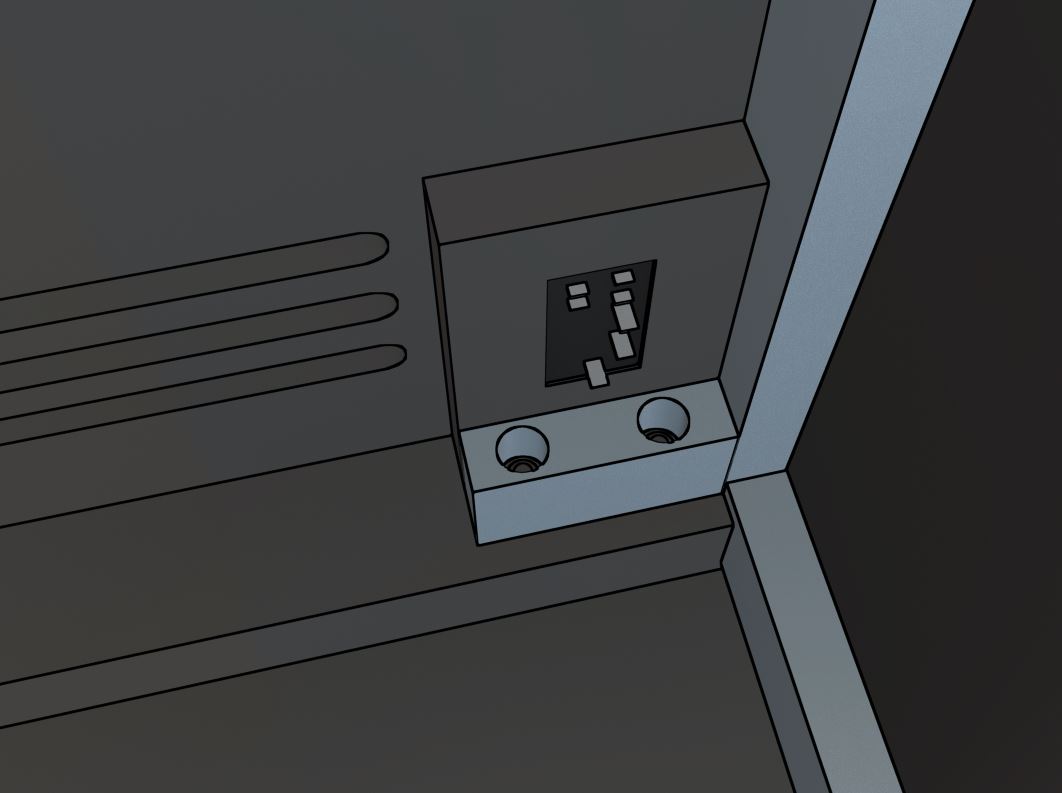
I also experimented a bit with an accent edge color for all my vents and inset areas on the back. From straight on everything is black, but the more you angle your view the more you see edge color. This would match the blue T-Molding I plan on using. Thought this might add an interesting special touch.

Here you see the full back arrangement straight on, so it's all black. I wanted to make sure I had plenty of vents to keep a good airflow going through the cabinet to not require any fans. I also wanted to make sure you can't see into the cabinet, so each vent has a 3/4" spacer behind it with a piece of hardboard attached, so it's impossible to see in from any angle while still promoting good airflow.

Lastly, here's some of the new details worked out for the main electrical wall. I plan on covering all the connection points with hardboard to keep young hands away and still need to design a cover for the back area of the mounted power supply. I will probably be good with a standard outlet box to cover the back of the main power inlet.
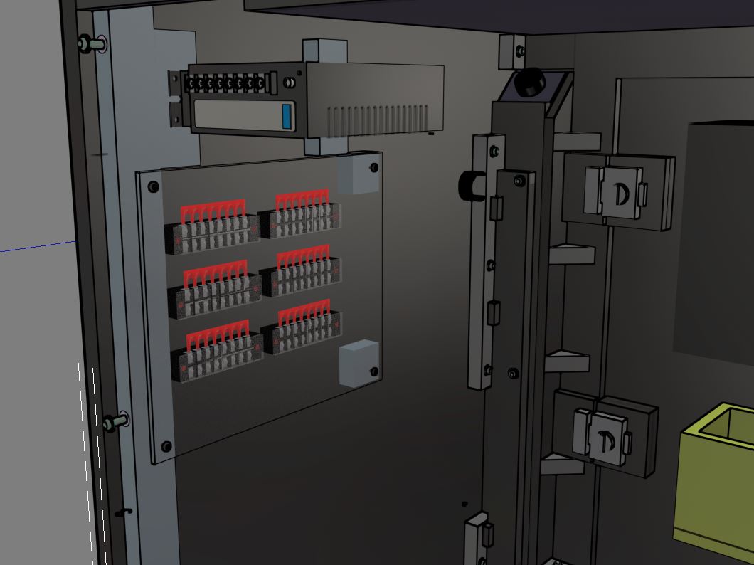
On the right side of the above pic you can see the inner details of the inset side design I added to the front. There's a long thin strip of hardboard over it in the back to cover the long channel of lights you will see in the front. I also am playing around with turn locks that I think I may go with that keep the main lower front cabinet door closed. You can access it through the coin door with the key. That keeps the front looking more like a traditional arcade with no extra handles and gives me a way to seal it up if I don't want people accessing the inside. I'm also toying around with a slide out coin catch drawer kinda similar to what Arroyo had in his designs. Still working out details for that. I also doubled up most of the wood on the front cabinet area to make it almost 1 inch thick just to reinforce the door areas and some otherwise rather thin long strips (1.5x30) that felt too flimsy and bowed to me if left at only 1/2 inch thick.

Now as far as wood working and assembly goes, I started by reviewing the base. Turns out there were a few mistakes I needed to correct before I could move on. The first was on the large board across the back. I had intended there to be a nice tight joint where long cleets from the side panels would sit into this board. I clearly was not careful enough on this section because my measurement was off and the cuts were kinda sloppy from the jigsaw. Pretty sure I let my boys help with some of these cuts...so I'll just blame it on that.

Either way, the holes on both sides needed shifting, so I broke out the chisel set I got a while back and did what I could to widen them out. It's not that pretty, and is too wide now due to how it was originally cut, but it should be corrected and still has board in front on either side. If I care enough I might try to pretty it up somehow later on with some covering.
Next up I took my time and carefully mapped out the bottom 4 holes for threaded inserts in my side panels. These are meant to connect to the base.


These came out ok. The only major setback was that I couldn't get the inserts to thread in enough to be completely flush with the board. Not a big deal though because they compress into the pine boards on the base and become flush. The first side I tested came out great. Everything actually lined up well and with some subtle adjusting I was able to get the side to stick below the base by exactly 1/16th. Then I went to test out the other side, and trouble struck hard.
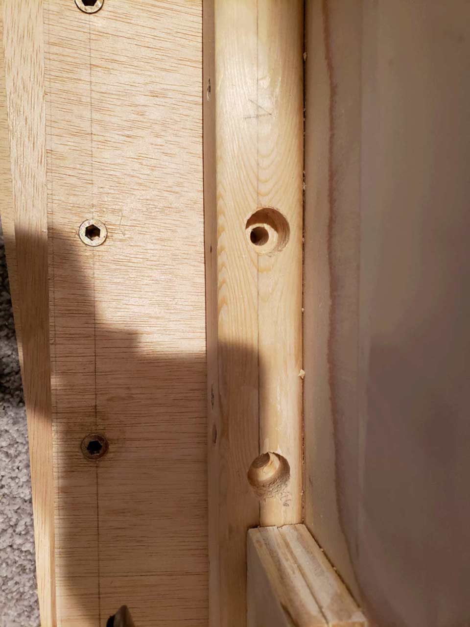
I can't explain this misstep at all. Clearly I have a line marked where the center of the holes SHOULD be....but this is no where near. I thought maybe I marked the other side and flipped the board wrong when I attached it, but in looking back at my design, it was suppose to centered, so it wouldn't have made a difference. Either way, I now had a problem to solve. Since this was for a part never seen and I didn't want to attempt to rip off that piece of the base and lose a bunch of time redoing it, I decided to try altering the holes manually with a free hand drill approach.

Turning the small hole into a capsule shape wasn't too tough and that would get it where it needed to be. The harder part was lowering the large inset circle on the other side that the washer and bolt rest on at a specific depth.

This wasn't pretty but through a bunch of side drilling / cutting with different bits I was able to get it just wide enough without messing up the depth much. Finally I tried assembling it again and was able to get it in the correct position.

The next part is a ton of manual plotting. This took a lot longer than I had hoped, but it's imperative that everything be as accurate as possible...especially with threaded inserts. In retrospect I think I would approach this process different next time. Given the shear number of things to position correctly and total number of inserts, it might be worth printing out a large black and white print and using that to align all the holes quickly. A step further would be to do this on a piece of hardboard. Then you would have a nice template to get perfect results on the actual wood you intend on using, and it makes it easier to reproduce the whole cabinet in the future if that's your goal. Anyway.... in this process I discovered a few mistakes with the sides that I needed to adjust my designs to and roll with.
The first thing with the inserts was plotting out the main side cleats that run up the back of the side panels. These hold on all of the back, add stability, and hopefully give the side panel a little more protection against warping. When drilling these and putting in inserts, I discovered it was best if I clamped several boards together on all sides to help keep it from accidently splitting during the process. This also provided a wider area to rest my drill guide on.
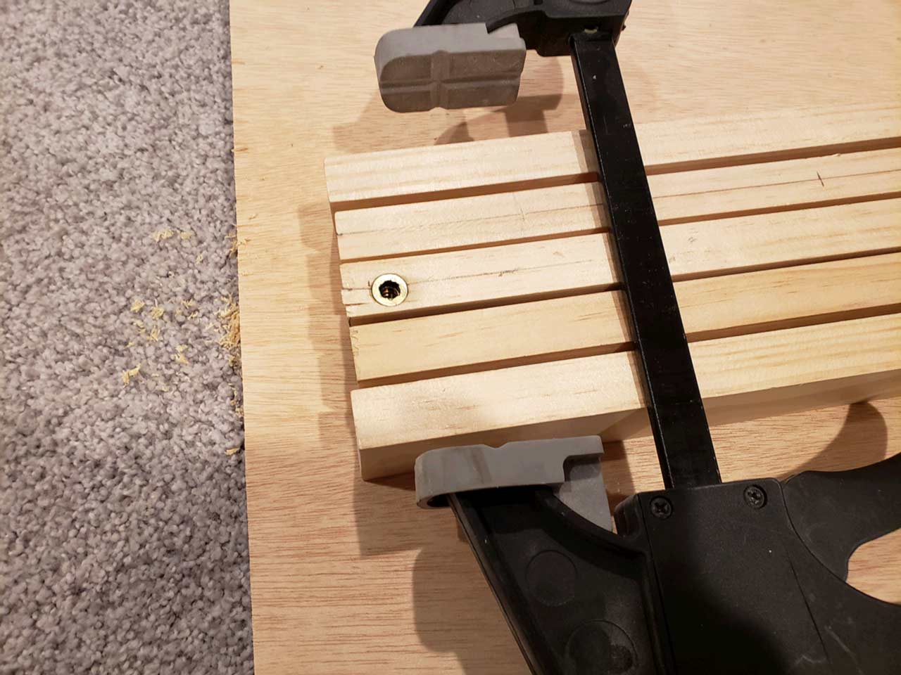

The screws are quick temporary holders while gluing on the side cleats. I may leave them in or I might just pull em out and fill the holes.
This next section is all the fun and pain I've run into dealing with threaded inserts and accuracy.

First a little tip I learned from bperkins. I used a standard toilet bowl wax ring and lightly rolled the insert on it prior to insertion. It turns out a little bit goes a long ways, and it definitely helps it go in faster and easier. It's even easy to remove and reinsert again if needed.

It turns out there's a lot more to these than meets the eye. Getting them to be the exact depth and perfectly straight is no easy task. First I measured out where my fully inserted drill bit hit the ground surface I'm drilling into and mark that with the stopper on my drill guide. Then I use a tiny measuring stick with mm on it and measure down from that point to the depth I need. In this case I'm using 15mm 1/4-20 inserts. On the first side panel, I got lucky and apparently went just deep enough to not run into an upcoming issue. On the second side panel though, I quickly noticed that each insert I added was also adding a noticeable bulge on the other side of the panel. The real breaking point was when I got to this section by the corner where the CP rests.

This is the repair shot. It ended up pulling the plywood apart! The crack wasn't very wide so I tried putting wood glue on some paper and was able to slide it in and try to wipe as much glue in there as possible, and then clamped it over night. At that point I made the decision that something was clearly wrong and I needed to figure out how to fix all these bulges, so I pulled out all the inserts on the panel.
Here you can see the regular depth required of an insert sitting against 3/4" ply.

There's only about 1/8th left which happens to be the final bottom ply and perhaps a thin veneer coating. This really doesn't leave much room for error, but it also doesn't explain the bulging and split wood just yet.
Next I used my scrap 3/4" ply to test more holes and try to understand what was really happening here. With what I thought was the proper depth hole, here's the insert threaded in to sit flush.

Now you can see the resulting bulge I was talking about on the other side, along with lots of cracking between the ply layers.
Here I made it a little bit deeper of a hole first, and in a cleaner section of the wood, and again you can see the bulge and cracking.

Eventually I drilled deep enough where it started cutting thru the other side.

After putting in the insert, here's the result.


So... now we have a new set of problems. This tiny hole shouldn't be an issue worth attempting to patch given that I'm laminating and it's the size of a pin head, but it's frustrating and if I were painting, this is not acceptable. It's also not acceptable to be this close to the surface if I'm thinking about inserts on my CP. I then backed it up by a hair and tested it again.


Finally. This is more acceptable (although still way too close to the surface....any sanding and a hole would likely surface).
I might have a couple different options to help this situation out. If I went with the next size down (10mm) threaded inserts that I got for 1/2" sections, and a shorter bolt, it would probably be fine with a shallower hole. However, then what will I do for the 1/2" areas I need inserts on?
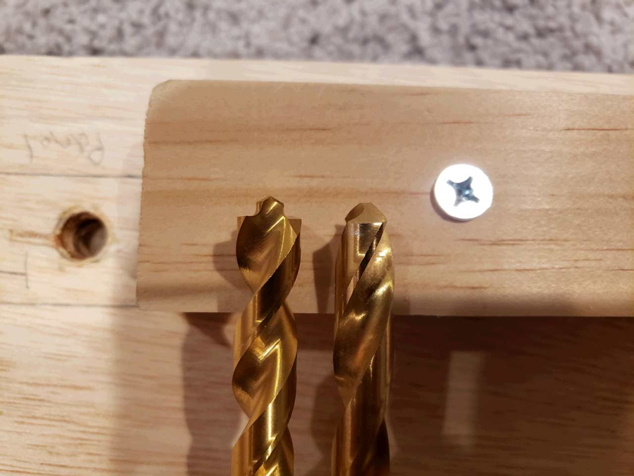
Turns out the drill bit selection I was using will definitely make a difference. I caught this early on but still don't have the best possible drill bit for the situation. Notice these 2 bits have different end points. The left one would cut a good 1/8th away before it starts to get to the actual diameter of the bit. The one on the right is what I used in all these examples. Still not ideal. What I really need is a flat ended bit so I can buy back 1/8th of depth. After a quick search I found some steel bits that kinda look more like what I need, but I'm not sure how it will handle wood.

You also run into situations where you need to find ways to make level surfaces to drill on. This wasn't even the worst one. The top section had 2 holes right next to a cleat so I had to measure the thickness of the cleat plus the hole depth and get it just right where millimeters count.
After I found the depth that didn't make a hole all the way thru, I went back over every hole on the panel and drilled each one more time. That was just enough and took out all the bulging, and left no holes (although it's still mighty thin).

So here we have 2 completed side panels with all the inserts in place. There are quite a few...72 in all. This is as far as I was able to get. At this point I probably won't be able to get back to the project until the new year. This feels like a lot of the complex parts though. A lot of the remaining pieces are rectangles and attaching cleats to those with drill holes for the bolts to pass thru into the inserts on the side panels. I already have all the primary panels cut to stand it up so it's really just attaching cleats. Hand drawing all this detail out on the sides revealed some flaws in my measuring, flaws in my cutting, and even flaws in the digital design, So it's been a back and forth process and I'm trying to roll with the punches as best I can to keep it moving forward.


 Home
Home Help
Help Search
 Login
Login Register

 Send this topic
 Print
Print Topic: The Kline's Arcade - 4 player - first build, help needed! (Read 52230 times)


