Main Restorations Software Audio/Jukebox/MP3 Everything Else Buy/Sell/Trade
Project Announcements Monitor/Video GroovyMAME Merit/JVL Touchscreen Meet Up Retail Vendors
Driving & Racing Woodworking Software Support Forums Consoles Project Arcade Reviews
Automated Projects Artwork Frontend Support Forums Pinball Forum Discussion Old Boards
Raspberry Pi & Dev Board controls.dat Linux Miscellaneous Arcade Wiki Discussion Old Archives
Lightguns Arcade1Up Try the site in https mode Site News

Unread posts | New Replies | Recent posts | Rules | Chatroom | Wiki | File Repository | RSS | Submit news


Author Topic: Mimic's Sister - Shapeshifter  (Read 102012 times)

0 Members and 2 Guests are viewing this topic.

bobbyb13

  • Trade Count: (+2)
  • Full Member
  • ***
  • Offline Offline
  • Posts: 1899
  • Last login:Today at 02:59:55 am
  • I believe I may need an intervention
Re: Mimic's Sister - Shapeshifter
« Reply #320 on: March 11, 2020, 07:29:18 pm »
Wow-

I just found this thread. Stoked to see you building this.
Ergonomics and controls are everything in the design phase and blending all of this like you have is outstanding.

And I thought my workshop was cool.  Yours makes me feel like my 10 year old set mine up.

The player's weight pinning the seat down is a great simple solution.
Which may still yet evolve, won't it?
Relax, all right? My old man is a television repairman, he's got this ultimate set of tools! I can fix it.

Mike A

  • Trade Count: (0)
  • Full Member
  • ***
  • Offline Offline
  • Posts: 5885
  • Last login:Today at 08:47:52 am
  • This plan is foolproof
Re: Mimic's Sister - Shapeshifter
« Reply #321 on: March 12, 2020, 07:49:34 am »
I am glad to see you are still plugging away. This is a big project.

Laythe

  • Trade Count: (0)
  • Full Member
  • ***
  • Offline Offline
  • Posts: 724
  • Last login:March 31, 2024, 02:52:10 am
  • "-smurfing- delivers." - Yots
    • forum.arcadecontrols.com/index.php/topic,149109.0.html
Re: Mimic's Sister - Shapeshifter
« Reply #322 on: March 23, 2020, 12:59:10 am »
Thanks, Mike A, bobbyb13 and Arroyo!

The player's weight pinning the seat down is a great simple solution.
Which may still yet evolve, won't it?

Yep, very possible, a lot of evolution is still going on in these parts.  I've got some aggressive traction rubber mat that I may use on the bottom rails as feet... but I may not have to.

Previously, on Shapeshifter:


I had made these nice 3/4" thick UHMW spacers to give the vinyl under the car seat plenty of room not to get pinched.  I taped together the parts for the 3/4" plywood base to go under the chair, and discovered...  the chair is a little too high for good knee room clearance, and also interferes just slightly with the keyboard tray off to the left under the VR buttons.

Interferes by about... 3/4".  Everything would be better 3/4" lower.   :banghead:

I can't shorten the skirts on the sides, because they just allow the chair to slide over the driving pedal frame when it's all nested together in pinball mode.  The interior space is right near the hard limit - any shorter, and it won't clear over the top. 

I thought of just skipping the spacers after all, but man, that might mean the vinyl would eventually chafe through, pinched between the steel frame and the plywood deck and fretting against it every time the seat cushions move...

Back to the drawing board.  Time for the spacers to lose some height.


Into the mill they go.

UHMW cuts pretty well, the bulk of the cut material comes off like snow, but sometimes the bottom of the cut comes off in a clear film almost like saran wrap or something - I think that may be due to local melting.  Still, makes a nice finish and cuts fast...


... though it makes a kind of impressive mess. 

Easy to clean up, though, that snow is very light, almost like styrofoam.  The shop vac picks it up with a vengeance. 

Here's the four spacers, knocked down from .750" to about .200" -


Then, I remade the top deck of the chair base in 3/8" plywood instead of 3/4" plywood.  The resulting stack is much slimmer:


That buys me back a touch over the 3/4" I needed to drop the chair by, without encroaching onto the space the pedals need to fit in.  3/8" plywood is about as thin as I am comfortable going in this spot, but given the chair bolts are close to the outer web, I trust it. 

Time to build the rest of the base. 

I took a 2x2 and ran it through the bandsaw diagonally to make some triangular stock for corner braces.


Here's the kit - 3/4" plywood to make the side and back walls.  (No front wall, because it's got to plug in over the pedals when you push it in.)


Wood glue clamped and reinforced by 6x 3" woodscrews per side wall, plus 3x more connecting the walls to each other, and 10x 1.5" screws yanking the triangular braces in on both sides, and we get the basic chair base structure:


I bolted the seat up to it to test it out.  Nice and stable, no side to side flex.  Boxed up, the 3/8" plywood is PLENTY strong enough.  If you get stupidly aggressive on the brake pedal to the tune of 2-3x the maximum control force, you CAN tilt yourself back a little on the carpet.  The chair doesn't slide even under that, it tips first.  That's reasonable enough; just don't do that. 

The height is better, too.  Knee room clearance is good. 

Here it is, in the room it will all eventually live in.


This is going to need a -ton- of bodywork, of course.  Lots of sanding, filling, sanding, priming, sanding, painting, sanding, and polishing in my future.  I'm thinking this may end up the dark grey color you can see behind it on Mimic, which is the same as the driving console and dashboard center, and darker than the black seat vinyl.  That, or black. 

I'm trying to get all the fabrication done, so that my next batch of filling/sanding/priming/painting bodywork can be the last batch; I go through too many foam brushes and rollers doing it piecemeal.  That goal would mean I'd need the back wall (done), the cross shelf (done), the pedal backframe (almost done), and the pinball table side skirts (not yet started) to all be ready.
« Last Edit: March 23, 2020, 02:32:22 am by Laythe »

javeryh

  • Trade Count: (+1)
  • Full Member
  • ***
  • Offline Offline
  • Posts: 7909
  • Last login:Today at 11:48:35 am
Re: Mimic's Sister - Shapeshifter
« Reply #323 on: March 23, 2020, 11:12:52 am »
Really cool stuff.  Your dedication is admirable too - that's a lot of work for 3/4"!  Will anything go inside of the space below the chair?

Mike A

  • Trade Count: (0)
  • Full Member
  • ***
  • Offline Offline
  • Posts: 5885
  • Last login:Today at 08:47:52 am
  • This plan is foolproof
Re: Mimic's Sister - Shapeshifter
« Reply #324 on: March 23, 2020, 11:22:16 am »
Farts. Lots and lots of farts.

PL1

  • Global Moderator
  • Trade Count: (+1)
  • Full Member
  • *****
  • Offline Offline
  • Posts: 9402
  • Last login:Today at 10:36:40 am
  • Designated spam hunter
Re: Mimic's Sister - Shapeshifter
« Reply #325 on: March 23, 2020, 01:55:14 pm »
I'll look forward to drinking beer and drilling farts into it if you build one.

:lol


Scott

Laythe

  • Trade Count: (0)
  • Full Member
  • ***
  • Offline Offline
  • Posts: 724
  • Last login:March 31, 2024, 02:52:10 am
  • "-smurfing- delivers." - Yots
    • forum.arcadecontrols.com/index.php/topic,149109.0.html
Re: Mimic's Sister - Shapeshifter
« Reply #326 on: March 23, 2020, 05:15:01 pm »
Really cool stuff.  Your dedication is admirable too - that's a lot of work for 3/4"!  Will anything go inside of the space below the chair?

Thanks! 

When it's all nested together in pinball table mode, the chair tucks in under the pinball table, and the pedals from the cockpit side go into that space below the chair.  So, yes:  Pedals.

Farts. Lots and lots of farts.

Also possibly this. 

The automotive vinyl is not very porous, it would require thunderous delivery... which I am neither prepared to rule out or issue as a challenge.   :lol

bobbyb13

  • Trade Count: (+2)
  • Full Member
  • ***
  • Offline Offline
  • Posts: 1899
  • Last login:Today at 02:59:55 am
  • I believe I may need an intervention
Re: Mimic's Sister - Shapeshifter
« Reply #327 on: March 24, 2020, 05:10:01 am »
Not sure where you live, but apparently you need to be careful who you invite over to help you break this creation in
Relax, all right? My old man is a television repairman, he's got this ultimate set of tools! I can fix it.

Laythe

  • Trade Count: (0)
  • Full Member
  • ***
  • Offline Offline
  • Posts: 724
  • Last login:March 31, 2024, 02:52:10 am
  • "-smurfing- delivers." - Yots
    • forum.arcadecontrols.com/index.php/topic,149109.0.html
Re: Mimic's Sister - Shapeshifter
« Reply #328 on: March 29, 2020, 10:22:10 pm »
As of the current design, the chair base I made in the posts above is going to run on wheels on carpet.  The wheels will be spring loaded, lifting the skirts of the seat base just above the top of the carpet so it rolls, but lightly sprung such that he weight of a person sitting in the chair drops the skirts to the ground and those then take most of the weight so it becomes stable.  (Kind of like those rolling stepstools you used to see in libraries.)

I'm going to use the rear axle as one of the springs.  It is 8mm diameter surface hardened stainless shaft.  I figure it deflecting about half an inch over a foot of run shouldn't make it take a permanent set, and feels like it's about the right stiffness as a spring to do what I want. 

I need a strong mount that attaches this axle to the center of the rear wall, offset by slightly more than the radius of the wheels, because the wheels are going to run inside the box and I want them not to quite hit the rear wall.  The wheels I liked best of about the right size turned out to be replacement wheels intended for those kick scooters - $9 with all bearings per pair of wheels, and they look nice. 

I rummaged around my shop and found a block of aluminum.  Laid out the shape of the mount I have in mind on it with a pencil, and grabbed it in the mill.


The milling machine makes a really rigid drill press.  The working space is tight, so I still use my drill press most of the time - but if you have a small part you want *precise*, this is a good way to do it.  I wanted this axle hole to be VERY perpendicular to the faces, so that an almost two foot axle would have the right gaps between the wheels and the back skirt wall way out on the ends.  With the big face of the block flat on the machining vise, and the mill trammed and square, this hole should be dead on.

I drilled it out, and did a test assembly on my work table.


Aaaand it's wrong.  One of the wheels rubs on the table.

 :angry:

The hole is square to the face, alright.  But the bottom edge of the block wasn't actually square, and that makes the block lean.  If I squared the bottom of the block, it'd be squared to the low side, and it'd be too short.  I could make a spacer to shim it out, but... I'm all of five minutes into this part, let's start over.

Back to the drawing board.  Dykem layout fluid, scribe some lines, rotate the part 90' and give myself more room to square up the block later....


Tweaked the design a little to just miss that first hole, drilled the new axle hole, and life is good, this will work.

The clearance above the axle will be tight to fit under the brake pedal, so the bulk of the clamp is toward the bottom.  Two screws in the front (left edge) will bridge across the slit cut and squeeze the gap shut against the axle, which should make it lock up tight.  Flange on the right, for screwing it to the plywood of the back wall.

To my beloved little bandsaw it goes, to rough it out:


You might think 1.25" thick aluminum billet would be hard to saw.  Sure, with a hacksaw it would be.  But not with this.

I roughed it out with a little gap to the line, because I plan to mill it for fancy appearance.


Milled to contour, and with the front holes drilled, it does indeed look kind of fancy. 


These holes in the front are 2" deep, and tapped 10/24 on the far side of the clamping slot.

I couldn't reach deep enough to tap the bottom of the hole, though, reaching through the front of the clamp to do it.  So, I was forced to shorten the cap screws a little bit; they still have a good inch and a half of aluminum threads, so they'll hold fine. 

Shortening screws on the knife grinder is just fun.   


Best done in short bursts with a water dip between so you don't screw up the heat treatment, but still, it's a sparkler.  It sparks joy, okay? 


Here's the complete rear axle assembly sitting on a table. 


When attached to the back wall of the plywood box through to-be-drilled holes in the flange, this will hold the axle and take in side load the weight of the human sitting in it, as the axle bows up, until the skirts hit the ground.  Takes maybe 30lb to do that, I think. 
 
The front wheels can't work this way, though, because they need to straddle the pedal frame.  They are next.
« Last Edit: March 29, 2020, 10:26:50 pm by Laythe »

Arroyo

  • Trade Count: (0)
  • Full Member
  • ***
  • Offline Offline
  • Posts: 1558
  • Last login:Yesterday at 04:24:05 pm
  • Budgets are boring
    • newforum.arcadecontrols.com/index.php/topic,156267.0.html
Re: Mimic's Sister - Shapeshifter
« Reply #329 on: March 29, 2020, 10:56:55 pm »
Damn dude.  Hella jealous of the metal working skills.  Couldn’t dream that up let alone build it.  Nice work as always.

Laythe

  • Trade Count: (0)
  • Full Member
  • ***
  • Offline Offline
  • Posts: 724
  • Last login:March 31, 2024, 02:52:10 am
  • "-smurfing- delivers." - Yots
    • forum.arcadecontrols.com/index.php/topic,149109.0.html
Re: Mimic's Sister - Shapeshifter
« Reply #330 on: March 30, 2020, 12:00:58 am »
Heh, thanks Arroyo.  This hobby is good for stretching your capabilities.  I'm impressed as heck at what you've been doing with The Grid, your precision is sharp and tidy and I wouldn't have come up with those illuminated panels or been comfortable setting up the addressable LED strips.  :applaud:


On with the suspension. 

The rear axle will mount in the box like so:


By design, the axle extends into the plywood a little.  There are slots cut on both sides the size of the nose of the axle.  The washer on the end can't fit off the end of the axle, even when the axle flexes, and the wheels run against the washers, so that keeps them on in that direction.  I'll be making some keeper tubes that slide over the axle to push the wheels out into those washers, but those aren't done yet. 

In loose parts and scrap, I had some links from a scissor linkage.  They are mild steel, have threaded 8mm holes in them, and are about the right dimensions, though they are a bit long.

Decided to use them as a starting point.


First, drilled one hole in each of them out to be a very careful slip fit on the rear axle, using the mill again to make sure it's very precisely perpendicular.  This is critical because this hole-axle fit is the main thing keeping the arms pointed forward, if it were loose they could wobble out of alignment. 

Then, shortened up the arms on the bandsaw just behind that hole, matching the shape of the other end. 

The front wheels attach via shouldered 8mm bolts into the front threaded holes, as stub axles.  Assembling all of that produces a rolling cart of sorts.


javeryh had asked if anything goes in the box under the seat - the answer is, all of this.  These pedals are gas/brake/clutch in a car, or left rudder/blank/right rudder in a flight sim, and behind them is a project box that will contain the power supplies and relays for driving the big actuators.  The wheelbase of the chair rolls in around all of it, and the box of the chair base just fits over all of it.

Speaking of close fits, to nest everything together I really need the axle further in than the edge of the pedals, so it slips under.  This drove the weird shape of the axle mount above.  Have a look at the vertical clearance between the bottom of the brake pedal and the top of the mount, when it's pushed in as far as I'd like it to go:


Laying that whole wheelbase/cart thing into the seat box, it looks like this.


I decided around here to flip the order - run the front suspension arms closer to the walls, and flip the wheels to the other side.  This design is still being evolved as I build it, as bobbyb13 noticed.  If I flip them that way, then the heads of the bolts are on the inside and I won't have to make matching slots in the plywood walls for the front stub axles.  This is good, because the back slots are a straight line, the front slots are a series of arcs around whatever height the back axle is flexed to... so the slot shape would have to be wide and complicated.

As of here, the front arms are floppy.  They need springs.  So, to the lathe to build spring hangers!


The chamfered spud on the front of these snaps into a short coil spring, if you wind the spring backward to make it expand.  Once it snaps in, it stays put very well.  I milled flats on opposite sides of them - one for the bolthead, one for the suspension arm - then drilled them to take an 8mm bolt, which threads into the next hole back in those scissor links. 

Shortened all the 8mm bolts down, and here's the setup on the floor:


The chair box will sit on the springs on the front, and on the axle mount in the back.  I think I've seen shifter karts with less complicated suspensions.   :lol

Flip it over, put it in the box...


Now I can see where the springs fall.  Those springs need shock towers to catch the other end of the spring.

Sliced up a 2x4, used a forstner bit to make a spring seat in the wood, cut them to fit, knocked some chamfers in them to be fancy, and set the height to where the spring would give me the roughly half inch of exposed wheel I want to see when it's not under load, and here it is - this is the idea of all the suspension, complete: 


It works, though it needs some adjustments here and there.  I'm going to make some C-shaped keepers to mount to the walls between the shock towers and the front wheels to limit the amount those arms can swing in, in case the holes between the arms and the axle tend to hog out over time.  I also need to relocate the rear axle hanger closer to the top edge - right now it all works perfectly on concrete, but with the nap of the carpet standing up, it rubs on the rear skirt under the weight of the box and seat more than I wanted. 

I think, other than adjustments, the suspension is basically done. 

I'm planning to put some rubber traction mat material along the edge to get a little more friction on the skirt bottom, just to be sure the chair doesn't slide on the carpet under aggressive pedal action. 

But next up, is...


more...


bodywork...

bperkins01

  • Trade Count: (0)
  • Full Member
  • ***
  • Offline Offline
  • Posts: 895
  • Last login:September 24, 2023, 02:13:35 pm
  • Plenty of skills.. gaining experience..
Re: Mimic's Sister - Shapeshifter
« Reply #331 on: March 30, 2020, 07:49:46 am »
Great update   :applaud: :applaud:  Thanks
My Arcade Cabinet Build and other projects here:
Centipede, Joust, Joust Cocktail, Asteroids, Galaga, Ms. Pacman Cabaret, Defender, Space Invaders Cocktail
https://bperkins.wordpress.com/

zestyphresh

  • Trade Count: (0)
  • Full Member
  • ***
  • Offline Offline
  • Posts: 60
  • Last login:July 31, 2023, 11:29:53 am
  • I want to build my own arcade controls!
Re: Mimic's Sister - Shapeshifter
« Reply #332 on: March 30, 2020, 08:09:37 am »
That is some awesome engineering there.

Laythe

  • Trade Count: (0)
  • Full Member
  • ***
  • Offline Offline
  • Posts: 724
  • Last login:March 31, 2024, 02:52:10 am
  • "-smurfing- delivers." - Yots
    • forum.arcadecontrols.com/index.php/topic,149109.0.html
Re: Mimic's Sister - Shapeshifter
« Reply #333 on: April 04, 2020, 03:16:20 am »
Bodywork.

Took the chair base pedestal outside, and sat in my driveway sanding up a storm.  Went from this:


down to this:


As you can see from all the circles of fill, this box has quite a few screws in it.  (38, to be exact.)

Unfortunately, at this point sanding I ran out of daylight, so I had to bring it into the shop, and alternate between hand sanding and vacuuming up the mess.

The filler on the inside leaves me some nice interior fillets that I think will make the subsequent painting nicer and easier.


Looks kind of cool, too, like wireframe graphics.

However, I rarely manage the whole fill in one pass successfully.  I ended up with some not-unexpected subsidence around the sunken screw heads on the outside.


That's nothing that another pass of filler won't fix, though...


I'm bidding three passes of filler, that's about par for me on this thing so far.

The sequence of finishing this piece is going to be weird, though.  I want to minimize how many times I install and remove the four screws holding the rear axle bracket to the back wall - and for maximum strength I want to use overlength screws, cut them off, and dress them down flush on the outside like I did with the backbox monitor hanging straps.  But, the axle can't be installed into the bracket after the bracket is installed, because of how it runs captive in the slots in the side walls.  And I don't exactly want to try to prime and paint the inside around the wheels and suspension.  So... I think the sequence for finishing this part has to be:

Mark and predrill the new correct positions for the four bracket mounting screws.
Prime the whole pedestal.
Sand.
Paint the inside black, with as much sanding and repeating as seems appropriate for hidden interior surfaces.
Install the suspension, with overlength screws that penetrate the back wall completely.
Cut off the excess screws, grind them a little below flush with a cutoff wheel
Do all the filler/sanding bodywork necessary to fix that screw grinding damage to the outside back wall
Prime the outside back wall over that bodywork
Sand.
Paint the outside... with a lot of sanding and painting and sanding and polishing, because this is part of the main exterior, and should therefore be nice enough for Ond not to shake his head disapprovingly at me if he ever sees it.   :)
Attach the rubber traction strips to the bottom edge.
Bolt up the seat.
"Test the software" some more.

LTC

  • Trade Count: (0)
  • Full Member
  • ***
  • Offline Offline
  • Posts: 201
  • Last login:April 07, 2024, 05:36:45 pm
  • I want to build my own arcade controls!
Re: Mimic's Sister - Shapeshifter
« Reply #334 on: April 04, 2020, 08:00:09 pm »
Looking good. You are almost to the finish line.

Laythe

  • Trade Count: (0)
  • Full Member
  • ***
  • Offline Offline
  • Posts: 724
  • Last login:March 31, 2024, 02:52:10 am
  • "-smurfing- delivers." - Yots
    • forum.arcadecontrols.com/index.php/topic,149109.0.html
Re: Mimic's Sister - Shapeshifter
« Reply #335 on: April 05, 2020, 03:19:28 am »
That is some awesome engineering there.

Looking good. You are almost to the finish line.

Thanks, zestyphresh and LTC!

Regarding the finish line, I disagree.  There are still parts of this thing that haven't even been started yet.  I'm almost to the final few dozen laps, maybe.  (grin)  But that's okay.

I mean, all the steps up there were for finishing the seat base.  Then there's a bunch of work to be done on the playfield counterweight arms, the back wall, the pedal floor, the power distribution/relay box, the midshelf... the TV tray isn't quite finished, there's a complete teardown necessary for some work that can't be done with it assembled before I can build Mockup v4.0 out of it...  I'm spitballing that this has got something like 4-6 months left, I think.

LTC's gonna beat me to a finished vpin by a landslide.  A good looking one, too - I'm enjoying watching that thread and seeing it come together.   :applaud:

Laythe

  • Trade Count: (0)
  • Full Member
  • ***
  • Offline Offline
  • Posts: 724
  • Last login:March 31, 2024, 02:52:10 am
  • "-smurfing- delivers." - Yots
    • forum.arcadecontrols.com/index.php/topic,149109.0.html
Re: Mimic's Sister - Shapeshifter
« Reply #336 on: April 12, 2020, 09:38:52 pm »
The march of progress continues. 

I'll compress a lot of boring hours here.  Primed the seat base over two sanded coats of filler.


Wasn't flat enough, once it was all one color and I could see the contour better.  So I put a third coat of filler on top of the primer and sanded that.


I've only got a little of the grey paint left, so I decided to do all the bodywork in black paint as a base to conserve grey for the final top coat. 

Painted it all black.


Wasn't flat enough, once it was all shiny and I could see the contour better.  So I sanded through that.


Then, it was flat enough!

So I painted it, the same grey as the center of the shifter console, the closest arc of the control panel, the pedal frame, and the majority of Mimic, which it will eventually sit next to.


No need to waste grey paint on the top center, as the seat covers that beyond the outside most inch border.

Here it is, in situ in Shapeshifter:


And with the seat mounted and everything stowed as a pinball machine:


In retrospect, it would not have been bad for the seat pedestal to have been done black like the sides of the console, but I think this grey will be slightly less obtrusive when it's sitting on a mid-tone carpet and help make the pinball mode look a little more like it's floating in the middle as a pinball cabinet would, instead of all becoming a big black mass down to the floor.

The seat rolls out nice on the bearings and wheels, my weight on it nails it to the ground and it doesn't move while running the pedals, so that all works.  Here's the transformation, still done by hand on Mockup v3.0:


This also shows my new approach of using the backbox monitor as a marquee when it's a cockpit game.  Not perfect, but, better than leaving it black and fun for bystanders at least. 


Next up:  The floor in front of the pedals, which shall contain a steel box full of power supplies and relays... and work on the pinball toys.

LTC

  • Trade Count: (0)
  • Full Member
  • ***
  • Offline Offline
  • Posts: 201
  • Last login:April 07, 2024, 05:36:45 pm
  • I want to build my own arcade controls!
Re: Mimic's Sister - Shapeshifter
« Reply #337 on: April 12, 2020, 09:54:47 pm »
Looking good. Keep it up  :notworthy:

javeryh

  • Trade Count: (+1)
  • Full Member
  • ***
  • Offline Offline
  • Posts: 7909
  • Last login:Today at 11:48:35 am
Re: Mimic's Sister - Shapeshifter
« Reply #338 on: April 13, 2020, 10:21:45 am »
Looks awesome.  You should just auto rotate the backbox 45 degrees so that the marquee is more visible to the player.... I kid, I kid.   :cheers:

Laythe

  • Trade Count: (0)
  • Full Member
  • ***
  • Offline Offline
  • Posts: 724
  • Last login:March 31, 2024, 02:52:10 am
  • "-smurfing- delivers." - Yots
    • forum.arcadecontrols.com/index.php/topic,149109.0.html
Re: Mimic's Sister - Shapeshifter
« Reply #339 on: April 14, 2020, 02:22:29 pm »
Haha, thanks. 

The LCD panel doing the DMD that runs through the neck of the backboard could certainly be twisted 45'... once...   :D

Laythe

  • Trade Count: (0)
  • Full Member
  • ***
  • Offline Offline
  • Posts: 724
  • Last login:March 31, 2024, 02:52:10 am
  • "-smurfing- delivers." - Yots
    • forum.arcadecontrols.com/index.php/topic,149109.0.html
Re: Mimic's Sister - Shapeshifter
« Reply #340 on: April 15, 2020, 04:44:19 am »
More progress.

On the virtual pinball cabinet side, I knew I wanted flipper contactors at a minimum - getting to play with Malenko's Gingerballs in person at Zapcon (wow that sounds wrong) convinced me that detail is worth the effort.  I didn't want to wire them straight to the buttons, because sometimes the buttons aren't live - I want them to fire when the flippers do, not whenever the buttons are pushed.  That means more software setup.

So, I messed around for a while and I got DOF working.  Now I can control various toys in sync with the tables. 
 
There's a standard way that most people do a bar of 5 flashers on a vpin - 3 watt RGB LEDs in pinball flasher housings.  The result is very bright, and that's what a lot of people want.  As this build has repeatedly shown, I prefer to do things my own way.  I didn't want something that aggressive - I wanted something a little more subtle and gentle, to add to the overall pinball table effect without leaving afterimages.

I found some C-channel aluminum extrusion that comes with a snap-in diffuser, 20mm wide x 10mm tall, originally intended for fitting LED strip tape into.  I also found some RGB LED modules wired in a string that would actually fit inside, 17mm wide x 6mm tall.  Digging around, I came up with some small chunks of additional diffuser material that came out of small LCD backlights that's only about 3mm thick, which will fit over the top of the modules under the diffuser cap strip.

I clipped off five LED modules off the end of the string.  Here's the raw materials.


First up, these LED modules as wired aren't individually controllable, you get one color for the whole string.  So, snip the switching ground leads between each module and run my own RGB switching ground lines to each module...


Then, splice it up.


Here's an early shot of testing the wire lengths and making sure the new extra wires could be routed around the sides of the modules.  It's tight, but it works.


I also sliced that supplemental diffuser material into strips the width of the channel, and stacked a long piece of it centered over each module. 

Time to test out the wiring.  Through two layers of diffuser it was still on the very bright side in my opinion, and I wasn't crazy about the white color when it's off, so I cut a chunk of 50% black window tint film and put that over it, which got the brightness right where I wanted and makes it a nice almost black when turned off.


You can see what it looks like without the window tint over at the left edge.


That looks like a winner to me, so I clipped it all down to eactly the width of my backbox.  I have a backglass monitor and a DMD monitor pressed close together, but they still have about an inch of deadspace between the screens.  My plan is to mount this flasher bar in that gap.  I drilled a wire run hole down at the bottom edge of the back, then tacked all the modules down in their carefully measured centered equidistant positions and routed the wires.  Since I'm bisecting the two backbox monitors, I can mount this fairly thin (10mm) package on the face of the bezels, and sneak the wires out in the gap where the DMD panel is much narrower than the backglass panel. 

I haven't mounted it up yet, but I did fake up a working mockup on the machine - here's the final effect, or, as close to how it really looks as I could manage to photograph. 


The flashers are still clearly three dots each, but they're kind of neat looking soft blended spheres.  Bright enough to be very present in your peripheral vision while you play, it adds to the activity of the backbox nicely but without punching you right in the freaking eyeballs.  It also nicely occupies the dead space gap between the screens.  (The window tint film is just draped over it here, so there's a bright corner at the left bottom and a gap at the right edge that'll be fixed when I really mount this up, sorry about that.)

When it's not lit up, it blends in pretty well as just a roughly T-molding sized raised black divider between the backglass and DMD areas.  It's unconventional, but, I dig it.

I'm going to play with adding an indirect flash of white LEDs for the strobes. I want to bounce it off the white wall behind the machine.

yotsuya

  • Trade Count: (+21)
  • Full Member
  • ***
  • Offline Offline
  • Posts: 19955
  • Last login:Today at 12:03:57 am
  • 2014 UCA Winner, 2014, 2015, 2016 ZapCon Winner
    • forum.arcadecontrols.com/index.php/topic,137636.msg1420628.html
Re: Mimic's Sister - Shapeshifter
« Reply #341 on: April 15, 2020, 12:29:38 pm »
More progress.

On the virtual pinball cabinet side, I knew I wanted flipper contactors at a minimum - getting to play with Malenko's Gingerballs in person at Zapcon (wow that sounds wrong) convinced me that detail is worth the effort.  I didn't want to wire them straight to the buttons, because sometimes the buttons aren't live - I want them to fire when the flippers do, not whenever the buttons are pushed.  That means more software setup.

So, I messed around for a while and I got DOF working.  Now I can control various toys in sync with the tables. 
 
There's a standard way that most people do a bar of 5 flashers on a vpin - 3 watt RGB LEDs in pinball flasher housings.  The result is very bright, and that's what a lot of people want.  As this build has repeatedly shown, I prefer to do things my own way.  I didn't want something that aggressive - I wanted something a little more subtle and gentle, to add to the overall pinball table effect without leaving afterimages.

I found some C-channel aluminum extrusion that comes with a snap-in diffuser, 20mm wide x 10mm tall, originally intended for fitting LED strip tape into.  I also found some RGB LED modules wired in a string that would actually fit inside, 17mm wide x 6mm tall.  Digging around, I came up with some small chunks of additional diffuser material that came out of small LCD backlights that's only about 3mm thick, which will fit over the top of the modules under the diffuser cap strip.

I clipped off five LED modules off the end of the string.  Here's the raw materials.


First up, these LED modules as wired aren't individually controllable, you get one color for the whole string.  So, snip the switching ground leads between each module and run my own RGB switching ground lines to each module...


Then, splice it up.


Here's an early shot of testing the wire lengths and making sure the new extra wires could be routed around the sides of the modules.  It's tight, but it works.


I also sliced that supplemental diffuser material into strips the width of the channel, and stacked a long piece of it centered over each module. 

Time to test out the wiring.  Through two layers of diffuser it was still on the very bright side in my opinion, and I wasn't crazy about the white color when it's off, so I cut a chunk of 50% black window tint film and put that over it, which got the brightness right where I wanted and makes it a nice almost black when turned off.


You can see what it looks like without the window tint over at the left edge.


That looks like a winner to me, so I clipped it all down to eactly the width of my backbox.  I have a backglass monitor and a DMD monitor pressed close together, but they still have about an inch of deadspace between the screens.  My plan is to mount this flasher bar in that gap.  I drilled a wire run hole down at the bottom edge of the back, then tacked all the modules down in their carefully measured centered equidistant positions and routed the wires.  Since I'm bisecting the two backbox monitors, I can mount this fairly thin (10mm) package on the face of the bezels, and sneak the wires out in the gap where the DMD panel is much narrower than the backglass panel. 

I haven't mounted it up yet, but I did fake up a working mockup on the machine - here's the final effect, or, as close to how it really looks as I could manage to photograph. 


The flashers are still clearly three dots each, but they're kind of neat looking soft blended spheres.  Bright enough to be very present in your peripheral vision while you play, it adds to the activity of the backbox nicely but without punching you right in the freaking eyeballs.  It also nicely occupies the dead space gap between the screens.  (The window tint film is just draped over it here, so there's a bright corner at the left bottom and a gap at the right edge that'll be fixed when I really mount this up, sorry about that.)

When it's not lit up, it blends in pretty well as just a roughly T-molding sized raised black divider between the backglass and DMD areas.  It's unconventional, but, I dig it.

I'm going to play with adding an indirect flash of white LEDs for the strobes. I want to bounce it off the white wall behind the machine.
I love what you did there with the LEDs. That was pretty smart, making your own individually controlled versions!
***Build what you dig, bro. Build what you dig.***

Mike A

  • Trade Count: (0)
  • Full Member
  • ***
  • Offline Offline
  • Posts: 5885
  • Last login:Today at 08:47:52 am
  • This plan is foolproof
Re: Mimic's Sister - Shapeshifter
« Reply #342 on: April 15, 2020, 12:32:16 pm »
Quote
That was pretty smart

You could apply that quote liberally to this whole build. :cheers:

Laythe

  • Trade Count: (0)
  • Full Member
  • ***
  • Offline Offline
  • Posts: 724
  • Last login:March 31, 2024, 02:52:10 am
  • "-smurfing- delivers." - Yots
    • forum.arcadecontrols.com/index.php/topic,149109.0.html
Re: Mimic's Sister - Shapeshifter
« Reply #343 on: April 19, 2020, 11:25:57 pm »
Quote
That was pretty smart

You could apply that quote liberally to this whole build. :cheers:

Hehe, thanks!

The next thing I've started work on, in pinball toys, is the "strobe".  I like an indirect bounced effect more than a direct one.  I'm running 8 GGG Novamatrix Linx 1st-gen white LED modules here, for 400ma total to stay comfortably within the 500ma per-channel limit of the LED-Wiz that's driving the pinball toys. 

Six of the modules go on the back of the back wall of the backbox, to bounce off a white wall several feet behind the machine.  There's a doorway back there, so it's possible to be behind the machine while someone is playing.  Since people can be back there, I want the strobe to be somewhat diffused and not a painful point source should you happen to be looking at it while it's going off.

I've got a certain amount of room between the three fans at the top of the backbox to mount two "strobe" units.  The space between fans is about 4.6" wide x 3.2" high, give or take.  The 3x NovaMatrix Linx package I want to put inside each lens ends up 3.5" wide x 2.2" high or thereabouts.

So I went on the hunt for a cheap prefab rectangular diffusing lens that was between 3.5" and 4.6" wide, and between 2.2" and 3.2" high. 

You know what turns out to be perfect?

The dome light out of a Ford Crown Vic.  Yeah, I'm running cop car dome light covers.   :lol  $6 apiece.

They are 4.2" wide by 2.8" high, so I should hit a nice even 0.2" gap on every side of the available space.

Here's all the parts together.


My lights are going to attach to the lower fan board of my backbox, which is removable, so that they in turn are removable from the machine for easier servicing.  The top fan board is permanently affixed, so they'll bridge over that seam by half their height, but only be attached into the lower.  Shown, two pieces of aluminum to make backer plates for that reason, some lightweight additional diffuser material to pack a layer of behind the lens, the lenses, some representative LED modules, and a chunk of plexiglass in protective paper.

As it turns out, the dome light covers have four L-shaped tabs that snap in to the housing in the original car.  I need to pick those up, and I need a bit more height to fit the LEDs under it, so I'm going to make some plexiglass spacer flanges that the lens covers snap into. 

Here's the layout on the materials.


The plexiglass mostly has the paper covering still intact.  Dykem on aluminum before I scribe out my layout gives me nice contrasting lines.  The rectangle I need -almost- fits on these scrap punchouts, so I'm using them, it'll work out when the bevelled corners happen at the end. 

This plexiglass job is going to be a tricky one.  Not a whole lot left when I'm done, as you can see. 

I drilled a hole near one corner of each block of plexi and laced the blade on the scroll saw through the hole.


The scroll saw blade is quite thin and flexible, so you have to be careful not to sideload it too much or you can knock a curve into your edge. 


It runs fast enough to melt the plexiglass a little - it's best to cut forward for about an inch and then back up, which peels the semimolten swarf back out of the cut.  Feels kind of like breaking the chips out of a tap with frequent reversal.


Still, with a bit of care and persistence, it's not too bad to carve the whole piece out, leaving just this thin rectangular ring.


Unhooking the scroll saw blade, you can unlace the part back off it.  Little filing to address the fitment, some dremel work to make reliefs for the L-shaped tabs to snap into, and peel the paper to reveal... a flange.


Then just make another one exactly like it.


Here's the resulting parts so far, with the dome light lens covers snapped into them. 


I'm still going to bevel the sharp corners then sand and polish the outside edges down to something presentable.  Once finished, the LED modules will 3M tape on to the aluminum plates, with the wires routed through a hole in the plate; these plexiglass flanges will get the backs roughed up and epoxy onto the aluminum plates, and then whole business will get attached to the lower fan board and the fan board reinstalled into the backbox.  I think it'll look pretty clean, and look somewhat like I'd designed it in all along - which is not the case at all. 

Pinball toy status:

5-flasher LED bar, done and mounted.  Strobes, in progress.  Flipper contactors, acquired and vaguely planned for.  Knocker, candidate acquired, likely.  Bumper solenoids and slingshots, possible, supported but uncommitted at this time.  Shaker, extremely dubious, given everything that goes into this machine to change modes I'm not sure I want it all aggressively agitated.  Physical nudge, right out for that same reason.  If I ever do support nudge it'd be by moving a floating rubber grommet centered lockdown bar with the heels of your hand, I think.  But that's a distant "maybe in version two if I still need to tinker with it after finishing it" kind of thought.
« Last Edit: May 05, 2020, 06:54:03 am by Laythe »

Laythe

  • Trade Count: (0)
  • Full Member
  • ***
  • Offline Offline
  • Posts: 724
  • Last login:March 31, 2024, 02:52:10 am
  • "-smurfing- delivers." - Yots
    • forum.arcadecontrols.com/index.php/topic,149109.0.html
Re: Mimic's Sister - Shapeshifter
« Reply #344 on: April 22, 2020, 02:17:35 pm »
Brief update, finishing up those back mounted strobes.

The aluminum backing plates/reflectors screw into the lower fan board only, which is removable from the machine - even though they overhang halfway over the upper half. 


The plexiglass flanges I made, got polished up and finished; they epoxy onto the aluminum backing plate.


The dome light lenses snap into the flanges, and are still removable from them if I ever need to get in here to service anything in the future.  I doubt I will ever need to - the way these things invariably work, I'd only ever need to be able to access these internals if I had made them inaccessible.

All of this then gets reinstalled, and here's the final result:


Crown Vic dome light lenses fit pretty well into the space I had between fans.  It maybe doesn't entirely look like a bodged-on afterthought, which it completely is.

Arroyo

  • Trade Count: (0)
  • Full Member
  • ***
  • Offline Offline
  • Posts: 1558
  • Last login:Yesterday at 04:24:05 pm
  • Budgets are boring
    • newforum.arcadecontrols.com/index.php/topic,156267.0.html
Re: Mimic's Sister - Shapeshifter
« Reply #345 on: April 22, 2020, 02:27:55 pm »
Fits perfect!  Nice job dude, keep it up. :applaud:

wp34

  • Trade Count: (+3)
  • Full Member
  • ***
  • Offline Offline
  • Posts: 4794
  • Last login:April 10, 2022, 09:48:19 pm
Re: Mimic's Sister - Shapeshifter
« Reply #346 on: April 22, 2020, 02:40:17 pm »
Crown Vic dome light lenses fit pretty well into the space I had between fans.  It maybe doesn't entirely look like a bodged-on afterthought, which it completely is.

Dang that is cool Laythe.   :cheers:

Plus you get bonus points for using a scroll saw.

Laythe

  • Trade Count: (0)
  • Full Member
  • ***
  • Offline Offline
  • Posts: 724
  • Last login:March 31, 2024, 02:52:10 am
  • "-smurfing- delivers." - Yots
    • forum.arcadecontrols.com/index.php/topic,149109.0.html
Re: Mimic's Sister - Shapeshifter
« Reply #347 on: May 05, 2020, 06:38:57 am »
Continuing my trend of madly improvising strobe light flashers after the fact into places I did not think to design for initially...

There are two gaps in the floor of the front cabinet, to allow a socket or wrench to access the lower leg bolts.  You can see these gaps, down at the very bottom of this picture from almost exactly a year ago.

These gaps turn out to be almost exactly the same length and width as the LED modules I'm using as strobes, completely by accident.

You thinking what I'm thinking?

Yep, down-firing strobes to add more indirect light splash. 


I made some mounting plates that hold one LED module each, and extend several inches beyond them toward the centerline, fished them into place inside the extremely narrow front cabinet, and ran a screw up through the floor into each one.  You can remove the screw and remove the LED if you need the originally intended access to the leg bolts, but now if you lay on your back under the front cabinet and look straight up, you'll see this by each front leg:


(You can also see from this view that there's no floor to the VR button panel... but that might be how it ends up - I mean, who's really going to be looking at the machine from this angle?  This is the same logic that keeps me from feeling any need to diffuse these strobe LEDs.)

The result in a medium lit room can be estimated by comparing these pictures:

Off -


On -


Like the rears, I think this came up pretty slick for being a total retrofit hack job. 

Pardon the big shadow thrown by the temporary clamp holding the scaffolding board that squares up Mockup 3.0 here - that'll be gone soon.


This floor splash of light shows up nicely in your peripheral view while you're playing.  I like it.  Strobes are now complete.


The project is now turning towards the power control box.  This is going to be a steel project box located behind the pedals that contains a whole lot of power supplies, solid state relays, DIN rail and wiring, and is one of the places I'm very glad to collaborate with my father on, to make use of his superior EE chops.  This will support the power demands of the two big linear actuators to transform the machine, and pinball toys like the flipper contactors, slingshot contactors, extra ball knocker, and so on.

Here's the box, sitting on the wooden floor that fits between the rails of the pedal frame.


Marked out on it is a required aperture to be made for an 80mm filtered intake fan.  The exhaust side will go out a duct on the back wall.

I cut the aperture with a hole saw, drilled some other mounting holes, and got the fan mounted in. 

This power control box will interact with the floor and the back wall somewhat like so:


These brackets will go to thread inserts to make one side removable, as the whole machine comes apart into reasonably sized modules for the sake of rebuilding in the house instead of the shop when it's done.

The air duct exit on the back of the steel box will need a place to vent, preferably beyond the back wall, instead of under the playfield monitor.

I traced out where it lands, drilled holes in the corners, and carefully saber sawed the rectangular hole out between them.


Here's the result, as roughed out by the saber saw...


I got a bit of splinter out on the back side that I'll have to fill later, but since this is plywood, it all takes a lot of fill anyway.  Additionally, that side is going to live like 2" away from a wall when this thing is finished, so nobody but house spiders and possibly the supernatural senses of Ond will be giving it a close look.   :)


I finished up the hole with some files.  Here's how the power box duct looks sticking through it, from the back:


I think this should make for a decent exhaust.

The mid-shelf, the back wall, and this floor will be the next batch to get bodywork and paint, and I think they're the last batch left to go black. 

After that, the side skirts for the table will have to get made, and they will be the last batch to go red, and then... aside from final touch-up, I'd maybe be done with painting?...  What a thought that is. 

Arroyo

  • Trade Count: (0)
  • Full Member
  • ***
  • Offline Offline
  • Posts: 1558
  • Last login:Yesterday at 04:24:05 pm
  • Budgets are boring
    • newforum.arcadecontrols.com/index.php/topic,156267.0.html
Re: Mimic's Sister - Shapeshifter
« Reply #348 on: May 05, 2020, 04:55:18 pm »


This reminds me of the fancy kimono's that are hung on the wall when visiting the in-laws in Japan  :duck hunt

Looking good Bud, keep chipping away at it!

Laythe

  • Trade Count: (0)
  • Full Member
  • ***
  • Offline Offline
  • Posts: 724
  • Last login:March 31, 2024, 02:52:10 am
  • "-smurfing- delivers." - Yots
    • forum.arcadecontrols.com/index.php/topic,149109.0.html
Re: Mimic's Sister - Shapeshifter
« Reply #349 on: May 05, 2020, 07:33:40 pm »


This reminds me of the fancy kimono's that are hung on the wall when visiting the in-laws in Japan  :duckhunt


Hahaha, I can totally see it.

Tell the laundry to cut back on the starch - this thing's stiff as a board.   ;D

rtkiii

  • Trade Count: (0)
  • Full Member
  • ***
  • Offline Offline
  • Posts: 288
  • Last login:March 16, 2022, 02:55:49 pm
  • Ready to Build! Not building? Making Movies!
    • RTKIII Productions YouTube Channel
Re: Mimic's Sister - Shapeshifter
« Reply #350 on: May 06, 2020, 02:13:51 pm »
wow...this is amazing!

Laythe

  • Trade Count: (0)
  • Full Member
  • ***
  • Offline Offline
  • Posts: 724
  • Last login:March 31, 2024, 02:52:10 am
  • "-smurfing- delivers." - Yots
    • forum.arcadecontrols.com/index.php/topic,149109.0.html
Re: Mimic's Sister - Shapeshifter
« Reply #351 on: May 11, 2020, 01:15:32 am »
wow...this is amazing!

Thanks!  It's a big undertaking, but I'm currently optimistic that it will all work in the end. 

This weekend was about the power control box.  It's been pictured in a few prior updates; it lives on the floor behind the driving pedals, underneath the pushed in chair, in front of the back wall. 

When I first proposed this project, rablack97 voiced a concern that there'd be insufficient volume to accommodate the parts and wiring necessary for a good vpin because of the design.  This box is one of the places those guts live.

First, I had to cut and drill a lot of holes in the steel box.


(Then I had to remove a whole lot of conductive steel shavings and swarf, because that's not something I want floating around in here.)

My dad gets the credit for the creative use of space that follows...

A 12v power supply mounts flat on the lid.  A 24v power supply mounts -edgewise- on the lid.


The 12v will be running the 9 amp (max) table rotating actuator,  the 9 amp (max) control panel sliding actuator, and the intake fan. 

The 24v will be running the flipper contactors, the slingshot contactors, and the bumpers. 


Next I took a PC power cable, cut the insulation off half of it, and threaded it through a heavy duty strain relief panel entry. 


This will be the 120v AC in to this box for the various power supplies, and for the big 120v contactor I'll be using as a knocker. 


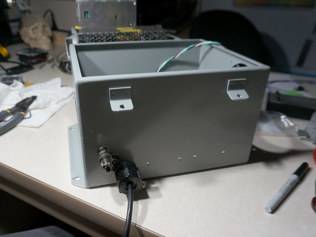
Immediately above and to the left is a fuseholder and fuse; power goes to it first, then everywhere else in the box.  Above and to the left of the fuseholder is the connector we'll be using to run up to the rotating playfield, for sending 24v DC to the flipper and slingshot contactors. 

Many outputs from the LED-Wiz in the back cabinet are wired to a DB25 connector in the front wall of the back cabinet; this box has the matching cable that attaches to that connector.  Then, inside this box, the LED-Wiz driver outputs will be flipping solid state relays.  So, this box gets a whole heap of solid state relays crammed into it.

To help mount those, I fabricated a neat little bracket out of sheet aluminum. 


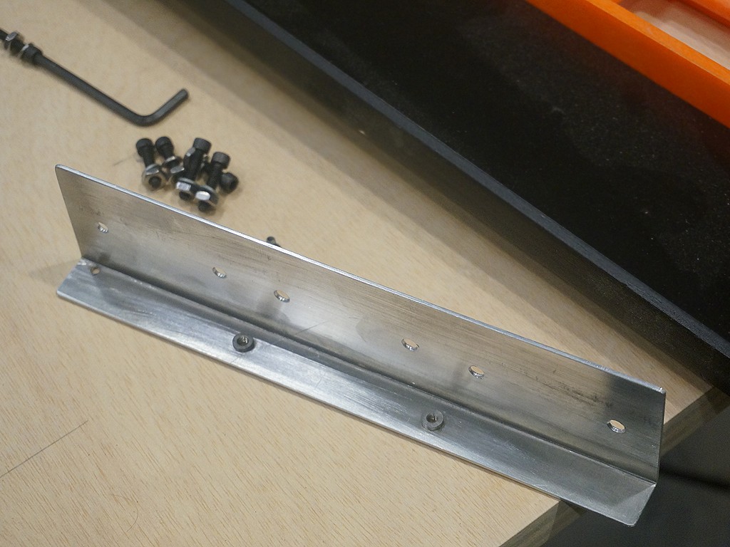
Cut out a rectangle of .060 aluminum, folded it to 90' on my little 12" finger brake, drilled it, and pushed in some pem nut thread inserts.

This thing mounts 6 solid state relays back to back, and acts as a heat spreader for them - here's a test fit of the four on the ends.


That's not enough relays, though, so some get mounted to the walls, too.  Here's the DIN rail, with terminal blocks and three more relays, and four solid state relays mounted to the back and left walls.  On the left wall, an 80mm intake fan, which will blow out through the rectangular duct I showed in my last update out through the back wall.  In the center of the box is the two holes for the aluminum bracket shown above.


When the solid state relay bracket goes into those holes, it all looks like this:


The tall 24v power supply swings in over the aluminum bracket full of six solid state relays, with about a half inch of clearance, which is half the wind tunnel going from the intake fan out the back of the box.  The flat 12v power supply swings in over the top of the DIN rail, with about 3/4ths of an inch of clearance, forming the other half of that air channel. 

This is most all the mounting that needs to go on to make the power control box mechanically complete.  It is likely to get disassembled again for wiring, of course, because getting into these spaces to wire it would be needlessly tricky. 

As oriented from the pinball player's perspective,  the front wall of the box has the 120v power, fuse, and a connector out to the playfield.  The back wall of the box has the DB25 signal cable to the backbox, and connectors for 1) the control panel stowing actuator, 2) the playfield rotation actuator, 3) the replay knocker, and 4) the various limit switches that will confirm to the PC whether the TV is horizontal or vertical, and whether the control panel is stowed or retracted. 

Next up is probably wiring, and some bodywork on the floor/back wall/midshelf - that's the last batch of parts to be painted black by my count.  I've cut the back wall and midshelf back to what I think - fingers crossed - the actual correct final distance from the front cabinet to the back cabinet should be.  Man I hope I got that dimension right, because it'll be a pain to adjust if I missed.

A great disassembly is coming on the horizon, probably 2-3 more updates from now, which will be a demoralizing thing to power through... but the next version of the assembly is the final assembly in the house, I think.  All work after that happens in situ.  Additionally, that reassembly is the one where it becomes motorized, so that's something to look forward to.
« Last Edit: May 11, 2020, 01:37:02 am by Laythe »

bperkins01

  • Trade Count: (0)
  • Full Member
  • ***
  • Offline Offline
  • Posts: 895
  • Last login:September 24, 2023, 02:13:35 pm
  • Plenty of skills.. gaining experience..
Re: Mimic's Sister - Shapeshifter
« Reply #352 on: May 11, 2020, 06:32:56 am »
That's some fine work  :applaud:   Very neat.  A please to watch for sure.  Thanks for the post!
My Arcade Cabinet Build and other projects here:
Centipede, Joust, Joust Cocktail, Asteroids, Galaga, Ms. Pacman Cabaret, Defender, Space Invaders Cocktail
https://bperkins.wordpress.com/

Arroyo

  • Trade Count: (0)
  • Full Member
  • ***
  • Offline Offline
  • Posts: 1558
  • Last login:Yesterday at 04:24:05 pm
  • Budgets are boring
    • newforum.arcadecontrols.com/index.php/topic,156267.0.html
Re: Mimic's Sister - Shapeshifter
« Reply #353 on: May 12, 2020, 12:25:49 pm »
Very cleverly put together Laythe.  Looks very professional. Looking forward to seeing that back piece get mounted and see this thing come together.

Mike A

  • Trade Count: (0)
  • Full Member
  • ***
  • Offline Offline
  • Posts: 5885
  • Last login:Today at 08:47:52 am
  • This plan is foolproof
Re: Mimic's Sister - Shapeshifter
« Reply #354 on: May 12, 2020, 12:34:01 pm »
din rails. :applaud:

markc74

  • Trade Count: (0)
  • Full Member
  • ***
  • Offline Offline
  • Posts: 807
  • Last login:April 20, 2024, 09:45:09 am
  • Flipping out
    • forum.arcadecontrols.com/index.php/topic,137295.0.html
Re: Mimic's Sister - Shapeshifter
« Reply #355 on: May 12, 2020, 04:14:13 pm »
Just wanted to pop in and say how amazing this is turning out. The level of skill and thought going into the individual components is insane.  :applaud:

I'm at the early stages of my vpin build (parts ordered - prototype playable) so it's awesome watching how you're building this.

rablack97

  • Trade Count: (+3)
  • Full Member
  • ***
  • Offline Offline
  • Posts: 2215
  • Last login:May 11, 2022, 06:50:10 pm
  • If you don't try, you have no chance at innovation
Re: Mimic's Sister - Shapeshifter
« Reply #356 on: May 12, 2020, 09:24:45 pm »
Hello Laythe,

I saw you doing some wire splicing, look into these, i started using these and its a huge time saver and a helluva stronger connection when splicing wires.

https://www.amazon.com/Connector-Qibaok-Waterproof-Electrical-Automotive/dp/B083DXC9TP?ref_=s9_apbd_orecs_hd_bw_bKkxsx&pf_rd_r=65N4EGKQS81NSK34Y3C0&pf_rd_p=37eb6949-eebd-5115-b141-3518d8964c41&pf_rd_s=merchandised-search-10&pf_rd_t=BROWSE&pf_rd_i=306720011


they have different gauges, try them out man, plus its all done with heat gun so you can splice practically anywhere without have to take everything over to your solder station.  AIO solder and heatshrink, when it cools the plastic shell hardens super strong connection.
« Last Edit: May 12, 2020, 09:31:08 pm by rablack97 »

Laythe

  • Trade Count: (0)
  • Full Member
  • ***
  • Offline Offline
  • Posts: 724
  • Last login:March 31, 2024, 02:52:10 am
  • "-smurfing- delivers." - Yots
    • forum.arcadecontrols.com/index.php/topic,149109.0.html
Re: Mimic's Sister - Shapeshifter
« Reply #357 on: May 12, 2020, 11:34:00 pm »
Hello Laythe,

I saw you doing some wire splicing, look into these...

Oh, nice!  Thanks for the tip, those look slick.  I'll give them a try!

rablack97

  • Trade Count: (+3)
  • Full Member
  • ***
  • Offline Offline
  • Posts: 2215
  • Last login:May 11, 2022, 06:50:10 pm
  • If you don't try, you have no chance at innovation
Re: Mimic's Sister - Shapeshifter
« Reply #358 on: May 13, 2020, 12:03:24 am »
Hello Laythe,

I saw you doing some wire splicing, look into these...

Oh, nice!  Thanks for the tip, those look slick.  I'll give them a try!

Heres a link to individual gauges, this is what i use on my splices today.

https://www.amazon.com/gp/product/B07J3V7SB3/

Awesome project sir...........

Laythe

  • Trade Count: (0)
  • Full Member
  • ***
  • Offline Offline
  • Posts: 724
  • Last login:March 31, 2024, 02:52:10 am
  • "-smurfing- delivers." - Yots
    • forum.arcadecontrols.com/index.php/topic,149109.0.html
Re: Mimic's Sister - Shapeshifter
« Reply #359 on: May 18, 2020, 02:31:58 am »
Awesome project sir...........

Thanks, man!  It'll still have a few compromises off a full dedicated vpin, no physical nudge for instance, but I am hoping it will still end up worthwhile.  I find it fun to play already, and I don't have any tactile feedback going yet.  But it will.  As Yots says...   SOON. 


Meanwhile, this is a small update on finishing up the look of the backbox.

Previously, you've been able to see some weird stuff around the DMD panel.  If I boost up the gamma on one of the recent shots:


On the left side of the DMD panel, you can see what was the under-monitor speaker grille of the monitor before I rotated it. 

On the right of the DMD panel, you can see a hole all the way through - if the back hatch is installed, it's painted black inside, but that's still been a gaping hole all this time. 

I cut a couple rectangles out of thin plexiglass to just snugly fit under the LED flasher bar, and over the floor, in height.  In width, they go from the outside edge of the backbox to the edge of the bezel of the DMD monitor.  Slapped them up against the speakers and used a sharpie to trace the speaker circles onto them - gotta say, it's sometimes real convenient to be working on clear parts, for cheating at fitment like that.

Used an old RC car body trick and painted the backside of them black, so the whole thickness of plexiglas acts like a clear coat. 

Turned out like so:


With everything off, you can see the window tint material on the LED flasher bar is a slightly blue grey compared to everything else, but in person it's more of a slightly mismatched black. 

This gives the backbox a more finished look.

When it's running, from the player's perspective, they turn out to reflect the pinball table playfield monitor in a kind of cool way:


(You can also see the bluish off-black of the LED flasher bar is less noticeable when anything is on the screens.)

Here's how they look while the LED flashers are running.


The new speaker blanker panels are just a little more reflective than the polished black latex paint on the neck below them.

I think this just about does it for things that will change with the backbox - that section of the machine is, as far as I'm currently aware, now basically complete.


Unfortunately, now it's time for the machine to go back under wraps for a while to protect it from the dust I'm about to make.


Reason being... I've got a heavy coat of filler on the mid shelf, floor and back wall.


and it's going to need a whole lot of sanding, filling, sanding, priming, sanding, painting, sanding and painting to get something decent from a surface that's starting out like this


Bodywork.  Then, more bodywork.  But these are, I think, the last three black-painted parts.  All grey painted parts are complete.  Two red-painted parts (table side skirts) have not even been fully engineered yet.  Paint is 80% pain, and I am 80% finished with the pain.