Hi! It took me two years of off and on work to accomplish this, because I am a) not handy b) not electrically adept. I wasted an extra couple hundred dollars looking for a nice rotating monitor solution, and this is what finally worked for me. Maybe you are like me, in which case maybe this will be helpful!
First, here is the video of the final result.
https://twitter.com/raphkoster/status/833219354116321281Special thanks to DaOld Man (starcom and assistance!), BorgDog (who pioneered doing a servo based monitor, and wrote the original batch file for the Micro Maestro), BadMouth for general assistance, the guys at HobbyTown for patiently explaining servos to me and for diagnosing all the ones that I killed or couldn’t power properly, and Pololu for answering software questions.
Parts neededCabinet: I did this by modding an Xtension 22” from
http://www.recroommasters.com/ Some of my instructions below will assume this Xtension cabinet, particularly the bits about the magnetic latch.
Monitor: I used a Dell 2700FP, which is what I already had in this cabinet. Make sure the monitor will fit while rotating; I had to debezel mine. Make sure it has VESA mount points on the back, and that they are centered on the monitor – otherwise, you will be doing some messy adapter plate work. Finally, make sure it has plugs that point down, not outwards.
Here’s the shopping list. There are some items you may well already have; there are some that you can avoid getting (for example, you could tap power from your PC in your cab for powering the servo. Note: you can’t use USB, you’ll need more amperage than it supplies).
| 1 | 3/8 inch Bore Clamping Hub | $7.99 | ServoCity |
| 1 | 3/8 inch x2 inch Precision Shaft | $1.39 | ServoCity |
| 1 | 3/8 inch Servo Shaft Coupler (Hitec) | $12.99 | ServoCity |
| 2 | 3/8" Bore, Face Thru-Hole Pillow Block | $25.96 | ServoCity |
| 1 | Standard Servo Plate A | $4.99 | ServoCity |
| 2 | Side Tapped Pattern Mount A | $9.98 | ServoCity |
| 1 | Shafting and Tubing Spacers (12 pack), 0.375” bore | $1.69 | ServoCity |
| 1 | 6-32 Zinc-Plated Pan Head Phillips Machine Screws (16), 1/2in | $1.28 | ServoCity, Home Depot |
| 1 | Hitec 645MG servo | $29.99 | Hobbytown, Amazon, ServoCity |
| 4 | #6-32 Phillips head machine screws, 1.5” length | $1.18 | Home Depot |
| 1 | 6-32 nuts (30 pack) | $7.64 | Home Depot |
| 8 | 1” washers with 3/16" bore | $2.36 | Home Depot |
| 4 | ¼” washers with 3/16" bore | $0.98 | Home Depot |
| 1 | Monoprice 200X200mm Bracket Universal Adapter | $16.36 | Amazon |
| 4 | VESA screws | $4.39 | Amazon |
| 1 | 3/4 in. Neodymium Rare-Earth Magnet Discs (3 per Pack) | $3.98 | Home Depot |
| 2 | 1" galvanized corner brace | $3.44 | Home Depot |
| 2 | Vinyl bumpers, 1/4" (they come in the assorted pack) | $4.16 | Home Depot |
| 1 | Micro Maestro 6-Channel USB Servo Controller (Assembled) | $19.95 | Pololu |
| 1 | 6V, 3A Power Supply | $24.99 | ServoCity |
| 1 | 2.5x5.5mm Female DC Power Jack / Male Battery Lead Adaptor | $7.99 | ServoCity |
| TOTAL | $193.68 | (plus shipping) |
In addition, you will need:
• 7/64” Hex key
• Phillips screwdrivers in assorted sizes
• Power drill with a ½” spade bit and a 1/4in bit for wood, plus a 1/8” for metal.
• A router
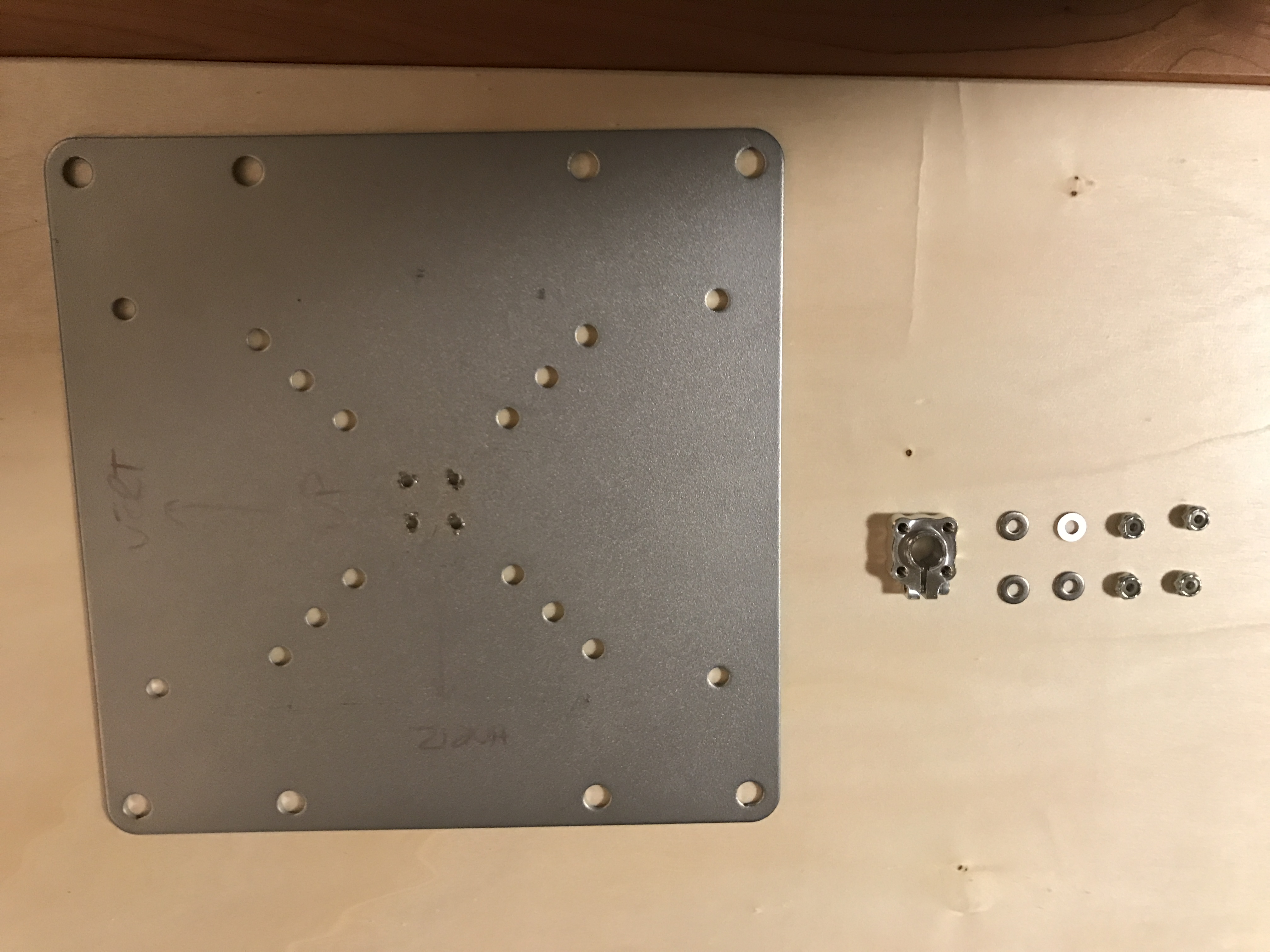
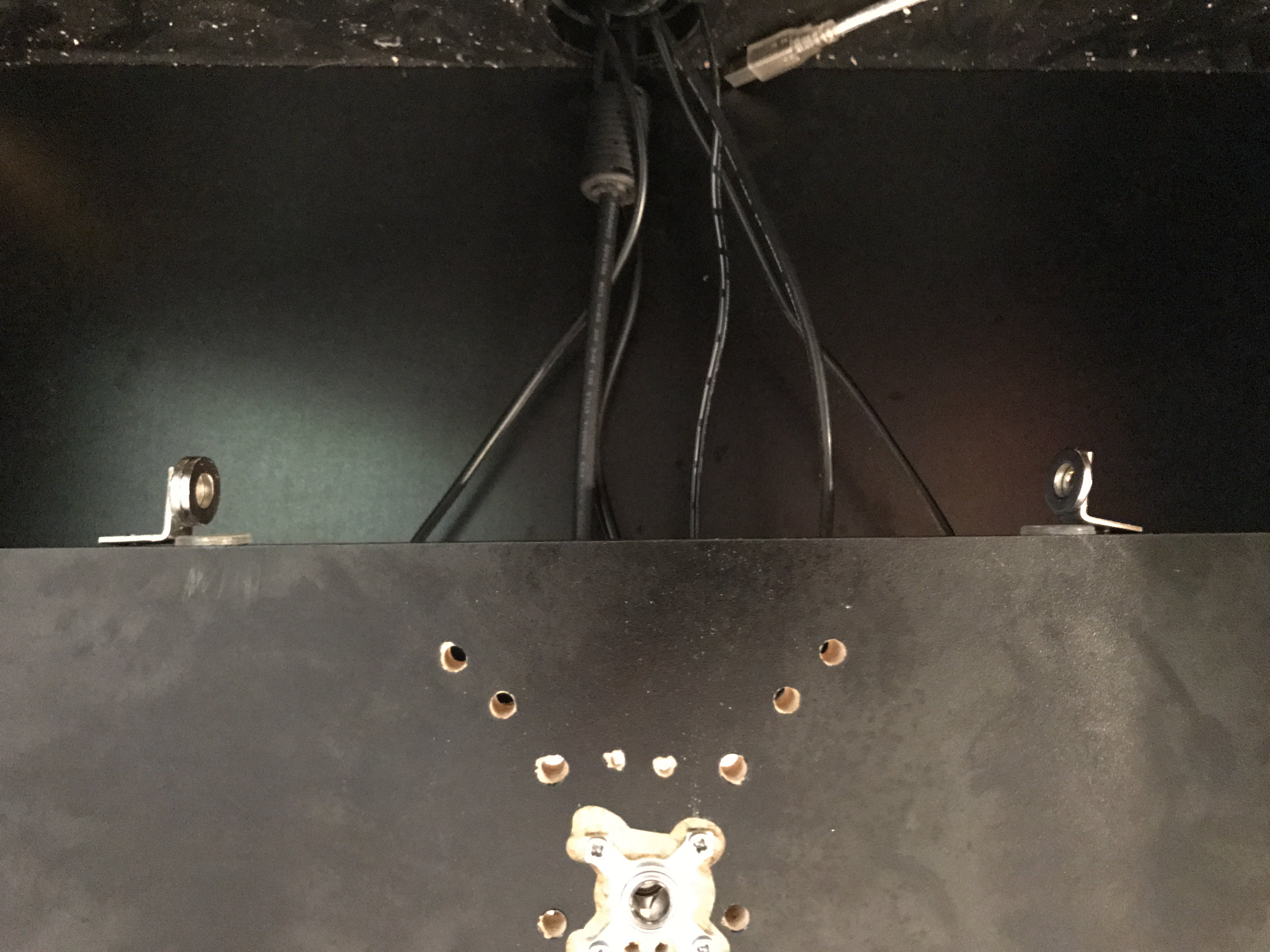
The mountCarefully identify the center of the cabinet back where you will mount the monitor. Measure like five times.

(The other holes in the picture are from when I tried a manual rotation bracket).
Drill with the spade bit to create a centered hole for the shaft.
Route out space on the front for one of the pillow blocks, and face it outward (flat side down).
If you don’t have a router, you can get a longer shaft and longer 6/32 screws (2in maybe?). I routed out the space because the monitor would be pressing against the bezel otherwise, so bear that in mind -- you want clearance there so the monitor doesn't drag against it.
Drill out holes for the long 6-32 screws. Be sure these are square, and straight!
Mount one of the pillow block bearings on the front by pushing the long screws through.
On the back, slide on 4 of the 1” washers, then slide on the other pillow block, with this one flat side facing the front of the cab.
Then put on four of the small washers on the screws.
Then put the two side tapped pattern mounts on, vertically. Be sure that they are turned the right way; they have an inside and an outside. You want maximal space inside for the shaft and the coupler.
Tighten the screws from the front; the side tapped pattern mounts are threaded, and will be drawn onto the screws.
Now is a good time to take your ¾” shaft and test that everything is square. It should slide in relatively easily – it may stick, but wiggle it and it’ll go in, and spin very freely once in there. If you’ve got binding now, likely you didn’t drill straight, just like I did! That’s why we’re using one screw all the way through this whole assembly, to ensure that stuff is square.
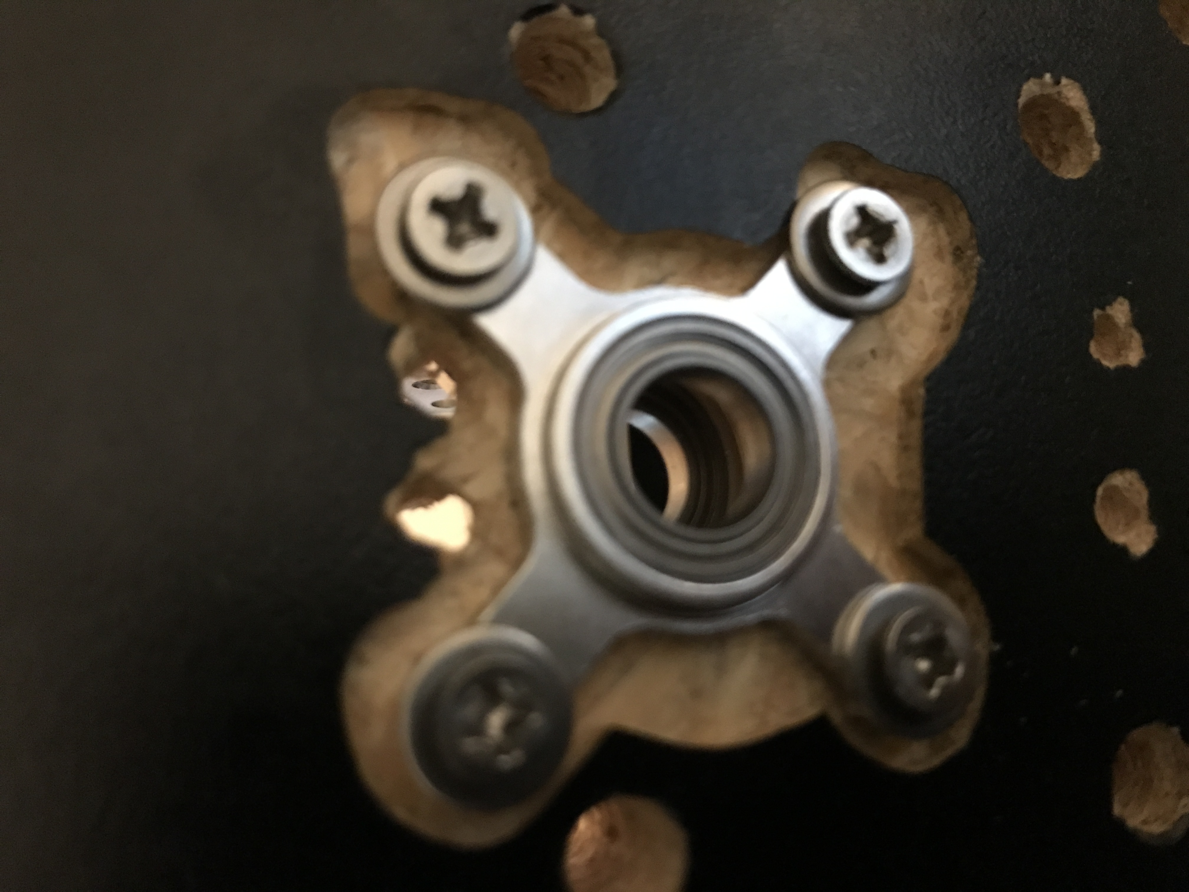
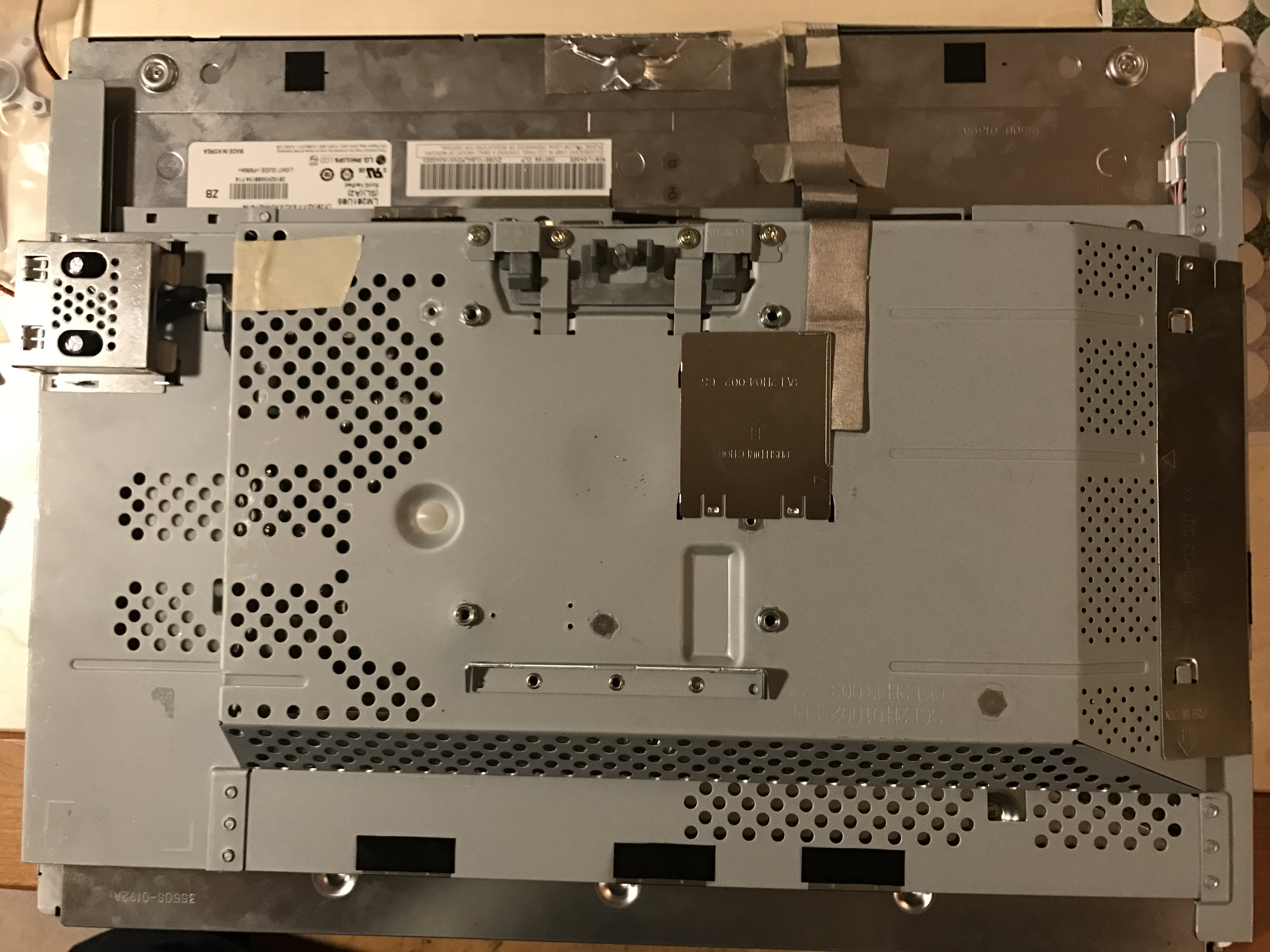
 The monitor and shaft
Debezel your monitor, if you need to. I did, so that i would have enough clearance at the corners when rotating. I also covered the silver up with electrical tape after debezeling.
Put the clamping hub on the shaft, but don’t tighten it up.
Carefully measure where dead center on the VESA plate is.
Mark the location for the holes to attach the clamping hub so the shaft is centered.
Use a drill bit for metal to drill the four holes. Again, these must be square, at a .77” square pattern on the diagonal.
Insert the shaft in the clamping hub, and tighten it down with a hex key.
Put a spacer on the shaft here.
Using 6-32 screws and 6-32 nuts (I used locking nuts on this one) attach the clamping hub and shaft to the VESA plate.
Using a sharpie clearly mark on both sides which way is up in horizontal, and which way is up in vertical. Vertical should be 90 degrees counterclockwise to horizontal.
Take the plate and try it in the mount again. It should spin freely. Note which corner is the one that is at bottom left when in horizontal and bottom right when it vertical.
Take two of the angle brackets and mount them on that corner using whatever screws and washers and nuts make sense. Don’t tighten then all the way yet, but tighten enough that it takes some friction to move them around. You want these mounted so that they stick backwards far enough to hit the back board..
Now when you spin the plate, those angle brackets should bump against the bottom edge of the back board that supports the monitor and stop it at perfect horizontal and perfect vertical.
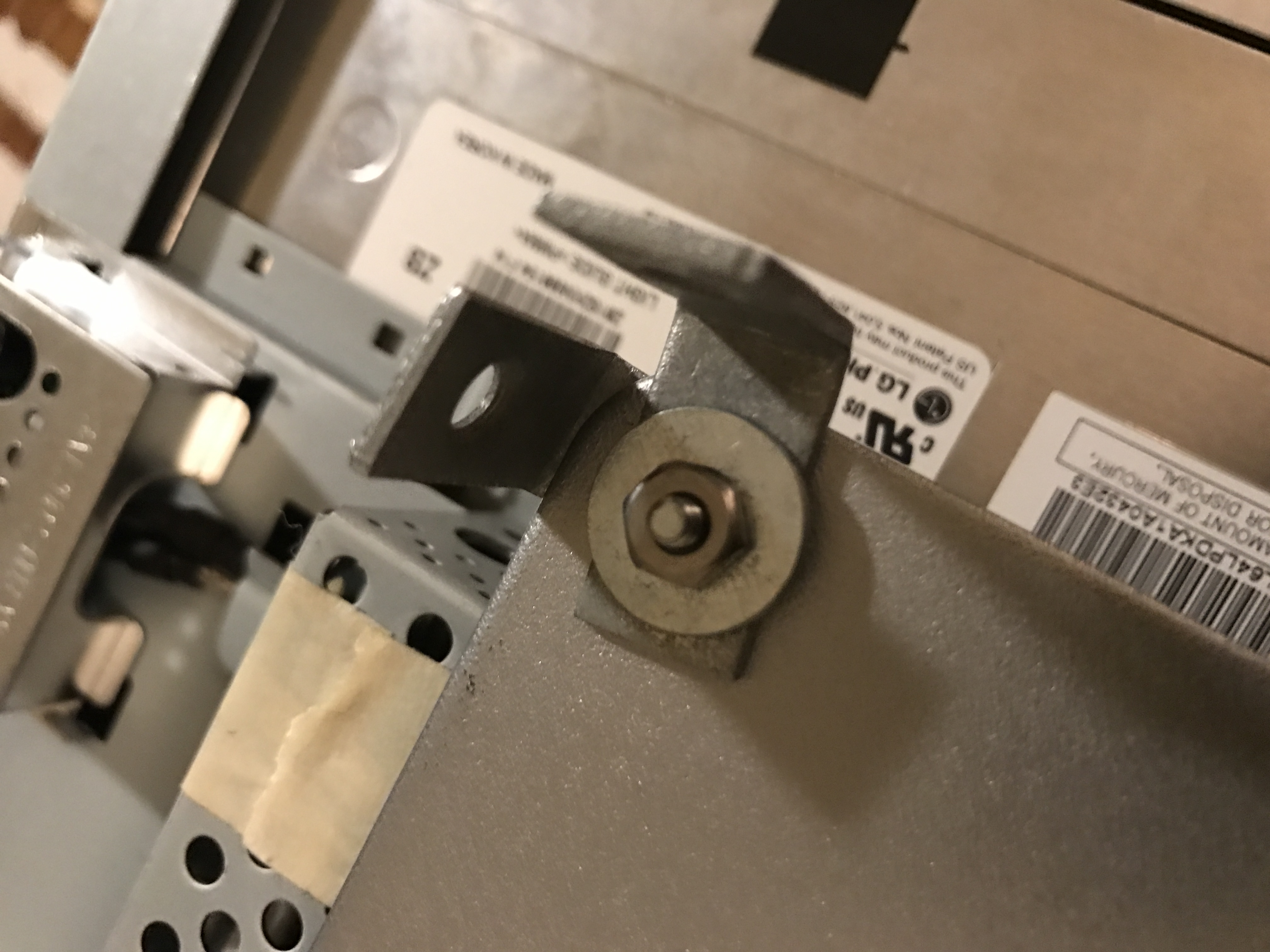
Put vinyl bumpers where the angle brackets hit that bottom edge. Now the monitor won’t be dead level in either position, so adjust the angle brackets until it is level in both positions, and then tighten that latch assembly down tight.
Take the other two angle brackets and use superglue to stick a magnet on each one, on the outside of the L.
Mount those two angle brackets on the bottom edge of that back board, against the edge of the vinyl bumper. You want the magnets facing inwards towards the center. Test that when you turn the VESA plate, the brackets on the VESA plate are catching lightly on the magnets. Make sure they don’t catch TOO well – the magnets are strong, and the servo can actually burn out or strip gears trying to pull away from them. I speak from experience. So make sure that the magnets maybe don’t quite touch the latch fully, etc.
Once it feels like it works, attach the VESA plate to the monitor using 4 more 1” washers and the VESA screws. Now is why you needed “Up” labeled in sharpie.
Now, you can take the monitor and carefully slide the shaft into the mount. It can be tricky, because now there’s lots of load. Push until it goes through both pillow blocks. Once in there, it should spin freely, but stop at perfect horizontal and perfect vertical thanks to the magnetic latches.
Take another spacer and put it on the shaft that is sticking out the back of the cab.
Turn the monitor to perfect horizontal and leave it there.
Electronics and softwareConnect the servo to the Micro Maestro. The pinout you need is here:
https://www.pololu.com/docs/0J40/1.a Basically, it goes in the second row of three pins, black wire facing out.
Connect the power jack to battery lead adapter. It goes in the first row of three, black wire out.
Connect the Micro Maestro to your PC using a regular USB to USB mini cable.
Connect the power supply to the adapter, and plug it into the wall.
It’s worth stopping here and mentioning that servos can have very high power draw when under load. This servo, the 645MG, can draw up to 450mA when it’s not under load, and probably can spike to 1-2A. I tried a more powerful servo than this, and it would spike to well over 7A… this power supply couldn’t handle it, and potentially could have died trying, and the servo didn’t even turn consistently because it was underpowered. So this servo and power supply solution are sort of an easy sweet spot. Feel free to power in whatever way you can, of course, but this is the “for Dummies” way. As long as the shaft turns readily and the pillow blocks and bearings are holding the load, this servo is enough to turn a 21" LCD and probably more.
Take one of the little servo horns that came with your servo – the one with just one long arm. Put it on the spline, but don’t screw it on.
Download the Micro Maestro suite, which will include the Control Center and the usccmd command line utility. It is here:
https://www.pololu.com/docs/0J40/3.aLaunch the control center, and make sure you can control the servo. Enable it on channel 0, play with the sliders, hurrah!
Now, put the servo all the way at the right end of that slider. Pop the servo horn off, and put it back on so that it is now pointing at 3 o’clock. (The spline -- the rotating axis connector -- is offset; the body of the servo points down, at 6 o’clock, the spline is towards the top, at 12.) This is now going to be your official horizontal position. Make a note of the value.
Now adjust the servo using the control center until the horn is pointing dead at 12 o’clock. It should be a 90 degree counterclockwise turn. Make a note of the value again.
Go to the Channel settings tab. Set this value as the low end. Set the value for horizontal as the high end. Set speed at 30 or so. Make the little pulldown for “on startup or error” read “off.” Save settings.
Go back to the main tab. You should now be able to drag the slider and watch the horn turn smoothly and at a nice pace from H to V and back again.
Move the servo to be at horizontal. Disconnect the power from the servo.
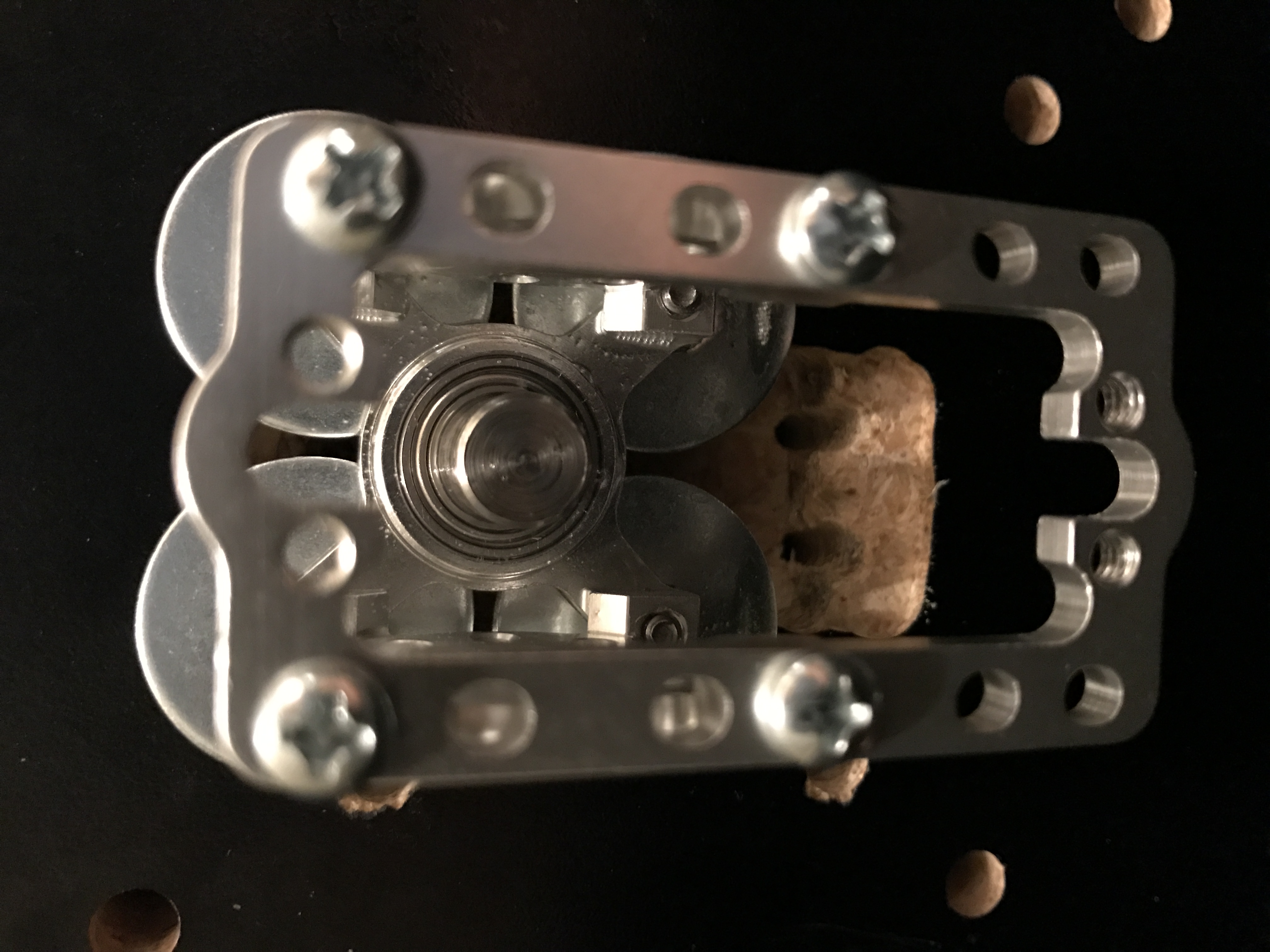
Slide the servo shaft coupler onto the servo spline in such a way that the screw for tightening it is pointing straight up (meaning, when you hold the servo with the spline facing you, the screw head should be pointing at the ceiling). Use the servo spline screw to attach it firmly there.
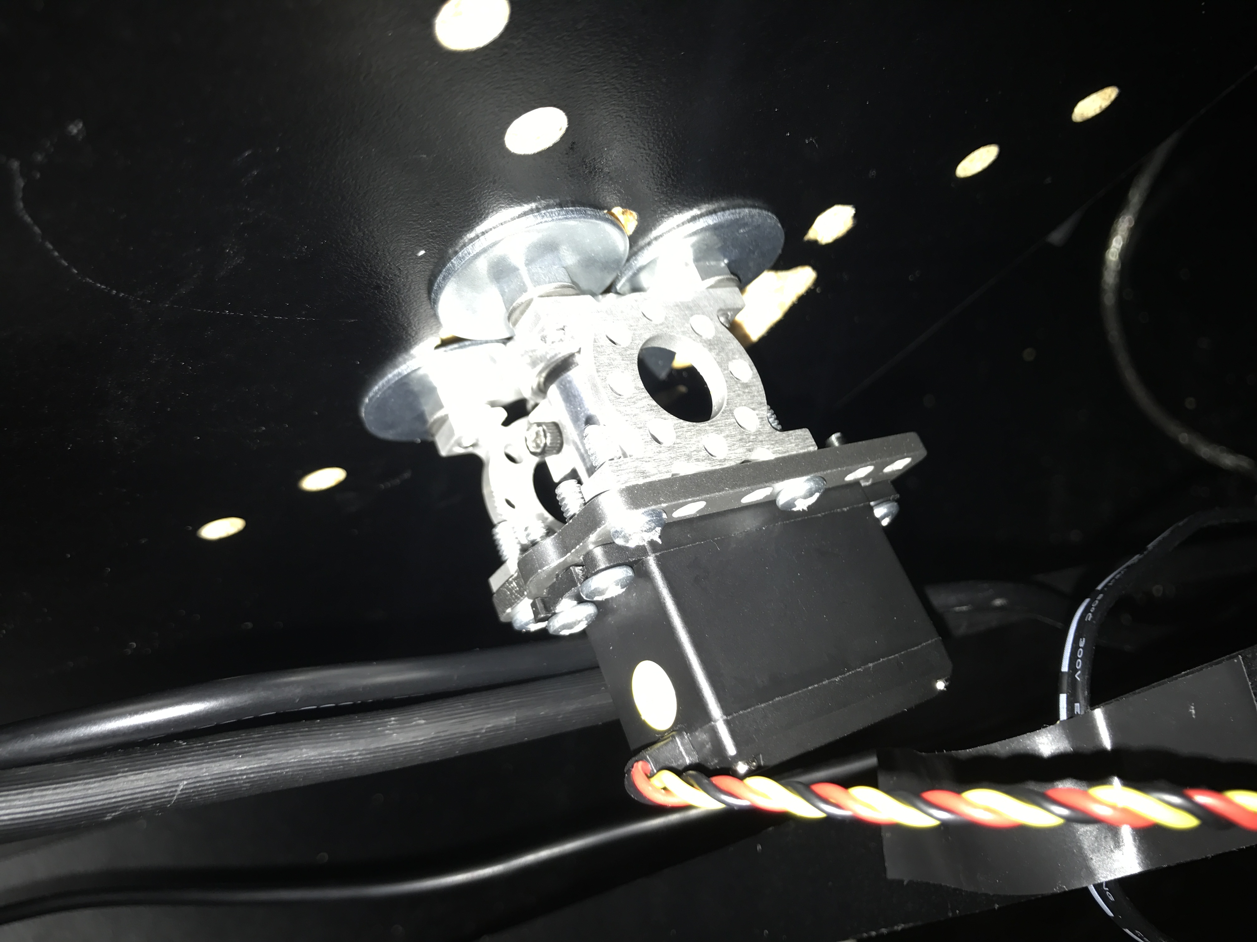
Slide the servo into the servo plate. You want to place the plate on the spline side, and you want the screws to go through the servo first, then into the plate. Otherwise you will not have enough clearance for the coupler.
Put the coupler and servo onto the shaft. Using 6-32 screws, screw the servo plate to the pattern mounts but don’t tighten it up. With the washers plus the spacer, you should have just about exactly enough space for the coupler.
Use a hex key to tighten the coupler down on the shaft. Now you see why we were so careful about leaving that screw pointing up!
It’s still loose, but we want to test. Move the monitor, and watch that the coupler (and servo) turns with it. Check that you are hitting the physical limit of the latches while still having servo travel. Check that you aren’t hitting the servo limits before you reach the latches.
If it’s all good, tighten up the servo plate. This will force everything to be square. Test everything again to check that nothing is binding.
Reconnect the servo power, and use the Control Center to test that you can move the monitor from horizontal to vertical, that the servo can pull free of the latches, that the speed on the servo is adequate so that it both turns freely, but doesn’t hit the bumpers so hard it bounces. I found that a value of 30 worked well for speed, and I used 0 acceleration, which actually means “as fast as possible,” but every servo is a bit different.
If your values are wrong, you may have to break the linkage between the monitor and the servo. The way to do this is to turn the monitor to horizontal, and loosen that coupler screw a lot (careful, it can fall out and get lost). Now the shaft can turn inside the coupler. Keep the monitor at horizontal, adjust the servo’s position somewhat, retighten, and test again.
Once you are sure you have the right values, write them down:
HORIZONTALPOSITION =
VERTICALPOSITION =
SPEED =
ACCELERATION =
But IMPORTANT: take HORIZONTALPOSITION and multiply it by four. Do the same for VERTICALPOSITION. (You don’t need to do it for the other two values).
Open a text file and name it servo.bat.
Paste in this code, originally written by borgdog but modded:
if "%1"=="90" goto vert

:horiz
d:\Utilities\Pololu\Maestro\bin\usccmd.exe --servo 0,HORIZONTALPOSITION
start /wait d:\Utilities\Pololu\Maestro\bin\usccmd.exe --accel 0,ACCELERATION
start /wait d:\Utilities\Pololu\Maestro\bin\usccmd.exe --speed 0,SPEED
d:\Utilities\Pololu\Maestro\bin\usccmd.exe --servo 0,VERTICALPOSITION
goto end

:vert
d:\Utilities\Pololu\Maestro\bin\usccmd.exe --servo 0,VERTICALPOSITION
start /wait d:\Utilities\Pololu\Maestro\bin\usccmd.exe --accel 0,ACCELERATION
start /wait d:\Utilities\Pololu\Maestro\bin\usccmd.exe --speed 0,SPEED
d:\Utilities\Pololu\Maestro\bin\usccmd.exe --servo 0,HORIZONTALPOSITION

:end
timeout /t 2 /nobreak
d:\Utilities\Pololu\Maestro\bin\usccmd.exe --servo 0,0

exit
Replace the all caps words with the values from earlier – the ones you multiplied by four! (You may have noticed that in the Control Center, you saw values like 3456.25 – well, the command line doesn’t do fractional values, so everything is x4 so you have the same granularity).
Also, obviously, replace the path to usccmd.exe with the path to where it is on your machine.
Close Control Center. You cannot run usccmd while Control Center is running, and vice versa – you will get crashes.
Make two shortcuts of servo.bat. Name one horiz and the other vert. Right click the properties on your new “vert” shortcut. On the Shortcut tab, in the line that says “Target”, add “90” inside the quotes but after usccmd.exe. Like so:
servo.bat 90Put these on the desktop. Now try out these two shortcuts to make your automatic monitor do its thing!
What this script does is: turns on the servo by telling it that it is where it is. Then sets speed and acceleration. Then turns it. Then waits 2 seconds, and turns it off. This prevents the servo from getting stuck and burning out, buzzing endlessly, etc. It also prevents the servo from ignoring speed limits when first started up. Unless the servo knows where it is, it cannot do speed and acceleration because it calculates those on the fly by using two known points. So it will throw around this very heavy monitor at top speed, thereby causing tons of torque, stripping the gear, loosening the mount, etc.
If you have made your latches too tight or too loose, you may need to tweak speed and the number of seconds for the timeout (it’s the “2” after the “/t”). Play with it until the monitor pulls off the latch easily, comes in smoothly for a landing at the target, and catches without bouncing.
Once satisfied, install the mrotate plugin from DaOld Man, if you’re running a frontend that supports it, such as MALA. If you’re not, find out if your frontend has the ability to run executables with parameters.
I had trouble getting startcom installed under Windows 10. I couldn't register comdlg32.ocx in Windows 10:
RegSvr32
The module "c:\windows\system32\comdlg32.ocx" failed to load.
Make sure the binary is stored at the specified path or debug it to check for problems with the binary or dependent .DLL files.
The specified module could not be found.
- registering comdlg32.ocx manually in Win10 just kept saying the file was corrupt.
- doing so from an admin-level command prompt didn't make any difference.
- running startcom with a copy of comdlg32.ocx in the folder gave an error saying that the .ocx wasn't registered.
- leaving a copy in the startcom folder and running startcom as administrator did the trick, and the ini was created!
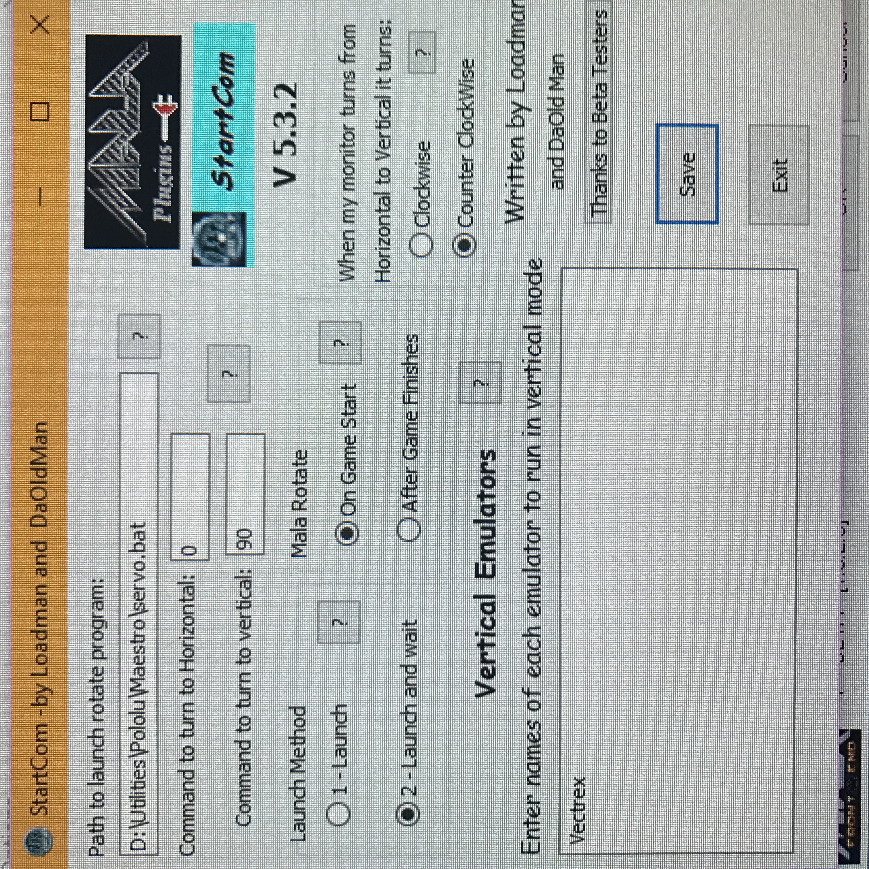
Now, in startcom, set values thus:
Put the path to servo.bat in the “Path to launch program” line. Make the command for horizontal be 0 and for vertical be 90. Choose “Launch and wait” for the method. Choose “On game start” for the “Mala rotate” choices. Choose “Counter Clockwise” for the direction. Then hit save.
Go into your mame.ini and set autorol to 0 and autoror to 1. And rotate to 1.
Refresh the games list, possibly using Mala’s handy "redo metadata in all game lists" button (I forget the exact name) under Game Lists. This will make sure the games that are supposed to rotate do.
The real testLaunch Centipede. Watch your monitor turn so that you are playing in portrait. Play until you die. Exit back to the frontend. Depending on whether you have both vertical layouts and horizontal layouts or not, tweak the Mala settings around rotation to taste. Personally, I made every layout for both.
Ta da!
FWIW, errors I made along the wayStarting by trying a manual rotation monitor, which lasted all of a week before I got annoyed.
Three different latch designs.
An under-powered, over-powerful servo.
Using only the servo itself without the ServoBlock mount.
A ½ shaft first.
Only one pillow block, which meant I ruined two bearings under excessive load.
Routing out the back of the board as well as the front, which wasn’t quite level, which caused horrible binding.
Stripping gears on a servo.
Lack of spacers, which caused binding.
Probably way way more.


 Home
Home Help
Help Search
 Login
Login Register

 Send this topic
 Print
Print Topic: How to do a servo-based automatic rotating monitor (Read 23546 times)


