I tested the factory game and plugged it all back together and everything worked - up , down switches are working and the enter/ start button - so all work - i then confirmed with a multi meter so we have eliminated the possible fault buttons at the arcade side.

what is meant by OHM out - i know OHM is is for Resistance- just not sure am i looking for zero ohms or a particular number or ohms ?
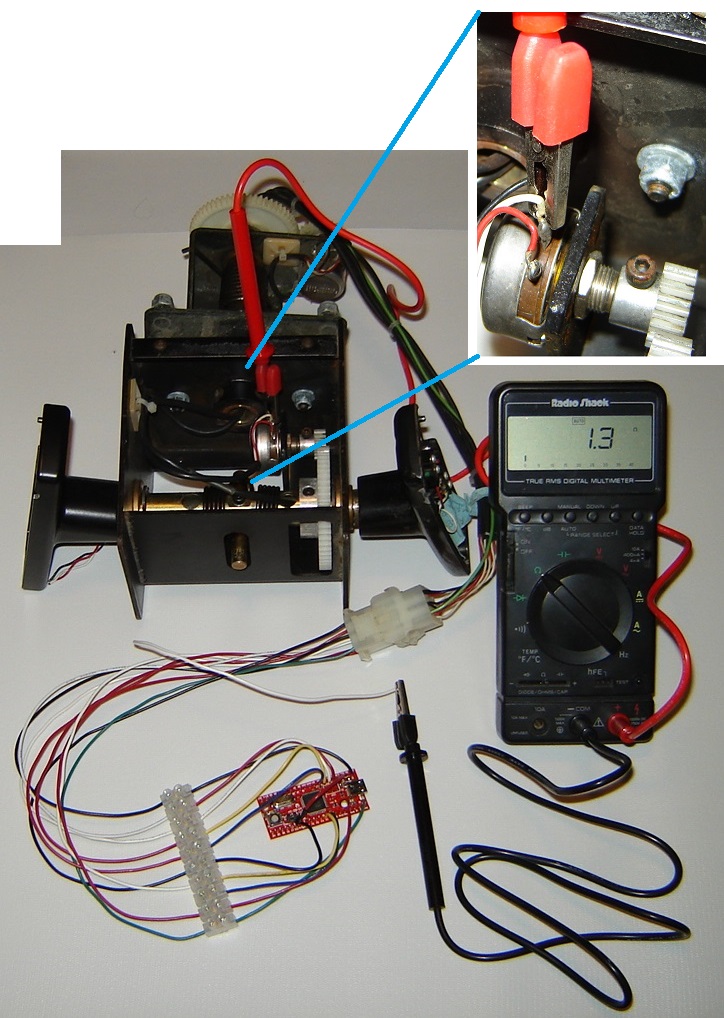
"Ohming out" is slang for using the ohmmeter to verify which wire is which and that the electrical connections are good like step #10
here.
Generally speaking, <2 ohms is considered acceptable.

As for setting axis - I have three (3) pots gas, brake, and angle, - and in the U_HID configuration utility my only options under analog axis are as follows: (which one should I use for brake)
Use any slider axis you like from 3-8 for brake.
Also if you have trouble keeping the steering wheel centered during gameplay, you MIGHT consider using "Axis 1 (x) with dead zone" but that tweak can wait until everything else is working.
Update 2 for today ...
Well things were not working at all so went back to the game and started to do another pin out ...
what i found out is that we are talking two different things - after a days worth of frustration i now realize when i was counting pins on sega unit ( looking directly at it reading from left to right i was getting different numbers - so I re continuity tested everything and had different numbers than you had.) turns out it all depends which end of the plug you're numbering from (male end or female side) female side is on the sega machine - where it was going all wrong was when i was making the male end loojing directly at it i was using same numbering scheme - ITS NOT when they connect - you need to look at the FRONT of the female plug and the BACK of the male plug for the pins to line up correctly ..
Any way all said and done
coming out of the sega machine ( the female plug here are the pin outs)
1
2- brake wiper
3- ground steering
4 Shift down
5
6 Shift up
7 steering wiper
8 anaolg ground for throttle and brake
9 throttle wiper
10 5v steering
11 start/ enter button ground
12 up ground / down ground
13
14 start / enter
15 5v brake and throttle
Sorry for any confusion, I was using the pin numbers on the schematic linked above.
Glad you got the specific wires/pins worked out.
The new problem Now - is configuring it all !!!! ARRRRG loaded game and it sort of works but not really - i played with the adjusters in the uhid utility for scale and offset and cant seem to figure out what they are doing? ? tried changing each axis individually and to the extreme but still not right....
the game the bike wants to go backwards and at full throttle goes slow or seems to spin wheel alot ... left and right is not response
Now I need to figure out how to adjust the pots so they work in the game. Any thoughts?
PROTIP: The purpose of troubleshooting is to figure out what is wrong by
eliminating possibilities and variables, not adding them.
Analog games introduce a metric butt-load of variables --
never use them for troubleshooting until you have your interface working correctly in windows.

If an axis is
backward in windows, there are two possible ways to fix it:
- Swap the 5v and ground wires (tabs 1 and 3) to reverse the axis
- U-HID may have a checkbox to reverse the axis (don't recall if it does)
If the axis works correctly in windows but is
backward in MAME, reverse the axis using the "Analog Settings" menu.
If an axis is not responsive in windows, check that the wiper voltage varies as you move the pot -- measuring at the molex is better than measuring at the pot for this reading.
- If not, there is either a wiring problem or a bad pot -- LMK and I'll provide further troubleshooting procedures to isolate the fault
Once you have motion on each axis and the correct orientation, there are three stages
**done in this order** to get things working right:
1. Adjust U-HID settings: (working from memory here, but this should get you in the ballpark)
- Scale changes the range of motion
The basic math for scale is max encoder voltage (5v) divided by the range of possible voltages from the potentiometer -- 5v / (V
high - V
low)
- Offset changes the center of the range of motion
The basic math for offset is the average of the low and high voltages from the potentiometer -- (V
low + V
high) / 2
Set your multimeter to Volts DC. (VDC)
Hook the black lead of your multimeter to analog ground and the red lead to the wiper wire of each pot -- measuring at the molex is better than measuring at the pot for these readings.
With the board plugged in, write down the lowest and highest voltages (the ends of the range of motion) for each axis.
If the steering wheel wiper varies from 1.25v - 3.75v and is at 2.5v when centered, that axis is centered (needs no offset) but needs the scale adjusted to double (200%? 2.0x? don't recall the settings values) since 3.75v - 1.25v = 2.5v ==> 1/2 of the possible 5v range of the encoder input.
If the pedal wipers vary from 0v - 3.3v, the axis is not centered (offset needs to be set so the center is at 1.65v) and the scale needs to be set to 1 1/2 times (150%? 1.5x?) since 3.3v ==> 2/3rds of the possible 5v range of the encoder input.
Once the U-HID is correctly configured, you should have motion on each axis that is fairly well centered, balanced, and covers as much range as possible
without hitting the edge before you reach the limit of motion. (clipping)
2. Use the windows gamepad properties window to calibrate the wheel and pedals.
When this is done, you should be able to move the full range on each of the three axes.
3. After those steps are done, the final tweaks are in the game itself.
Check out BadMouth's sticky
here in the Driving sub-forum for details on configuring analog controls.
Scott


 Home
Home Help
Help Search
 Login
Login Register

 Send this topic
 Print
Print Topic: 5k pots and setup with UHID for Sega Manx TT -> PC conversion (headakes) (Read 14443 times)


