There are a lot of Fix it Felix cabs out there and honestly I haven't looked at any of those builds. I'm not interested in duplicating someone else's work nor am I interested in standing out. I had an opportunity to buy a cheap DK cab and I liked the idea of a FiF cab so that's what I built.
Project Goals:- Build a cabinet that looks, plays and feels as close to the real Fix it Felix Jr arcade machines as possible.
- Build the cabinet in such a way that if I ever want to convert it back into a Donkey Kong there wont be any noticeable evidence that it had ever been converted.
- Add versatility to the cab to emulate many popular, fun, and classic arcade games that are compatible with the vertical monitor and 1-joystick 2-button control panel format. Make sure these games play as close to their original form as possible.
- have an easy to use, seamless and professional looking front that guests can navigate easily without instruction.
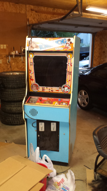
The Back Story:A non-collector friend of mine picked up an old blue DK from a government auction for $50, this had apparently been located at the state prison (they provide arcade games to the inmates? who knew?). It had a DK Jr PCB and played but he left it in his garage unused for a number of years until one day he decided to turn it on and just got garbage on the screen

He really didn't have any love for DK but did want a gun game like Buck Hunter or Area 51. and started asking me about how he might convert this cabinet into one of those... I told him this was a horrible idea and that if that's what he really wanted he should sell DK and buy a dedicated Buck Hunter or Area 51. He asked me if I wanted to buy it. Knowing full well that he paid $50 for it in working condition and now it wasn't working I offered $100 and he agreed as long as I put it to good use. He even delivered it. (though he does have access to a truck with a lift gate it was easier that way anyway).
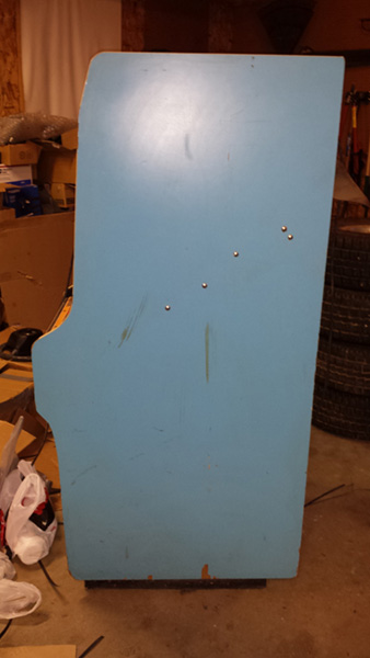
The cab was solid and mostly complete (missing rear door lock, missing coin catchers, missing marquee bulb and starter, no side art, large chunks of missing t-molding) It had original buttons but a non-original joystick, the monitor worked but the rest of the electronics were a mess.
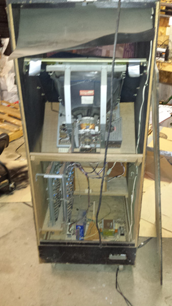
To my surprise there was actually 2 PCBs inside the cab it had both a DK and a DK Jr. it looked like they would just move the harness over to the other board on occasion. The rest of the wiring was a mess, the original PSU was gone and there was an old cheap switcher in it's place, the original harness had been replaced with some home-build piece of junk held together with wire nuts and hot-glue... Amazingly it seemed to be functional based on testing it with a meter, the PSU was junk so I tried the board with a good one I had laying around... still couldn't get either PCB to boot, I tried pulling, cleaning and reseating all the socketed ICs and that didn't help either. I looked it over for damage or bloated caps and still didn't come up with anything... had had exhausted the extent of my board repair knowledge.
The cab needed the chipped edges patched up, some fresh paint and t-molding a few other minor parts no matter what. From there I could dump a few hundred bucks into a board repair, an original harness, original PSU, original joystick, and some repo side-art. But I'm honestly not a huge fan of DK... I don't have any font memories of this game from back in the day (I grew up with Mortal Kombat and TMNT). I don't dislike the game, I do play it on occasion, but it's not something I like enough to basically build from next to nothing. So after thinking about it for a while I decided to build a MAME cab with a Fix it Felix Jr. theme. That would cost about the same as a full on DK rebuild but I'd be able to have a cab with a handful of classics on it that guests could enjoy since all of the other games in my collection are from the 90s and newer. I had considered a FiF built before I even bought the cab and with just about all the guts needing to be replaced or repaired this just made my decision easier. If I had managed to get one of the PCBs working I probably would have gone the restore route instead.
Other Games:I used a program called RomLister (
http://www.waste.org/~winkles/ROMLister/) to generate a list of MAME games that were compatible with my cab setup, My original goal was ~60 titles. Large enough to provide a good variety of games but small enough that I wouldn't be loading it with crap that no one was going to play and also small enough that I could play test/tweak the configuration of every game to make sure it's setup perfectly.
After some consideration I realized that there were a lot of 8-way joystick titles that I would really love to be able to play, mostly SHMUPS, rather than throw an 8-way in there and ruin the gameplay experience of all the 4-way titles I decided to buy a Servo-Stick (
http://www.ultimarc.com/servostik.html) This is a really great pice of kit sold by ultimarc, it uses a Sanwa joystick as the base but they've added an special restrictor plate and actuator to convert it electronically between a 4-way and an 8-way stick. This is controlled automatically by the front end based on the game you've selected so it's completely seamless to the user. Pick a 4-way game and the stick works like a 4-way, pick an 8-way game and the stick works like an 8-way. With this I expanded my game list to about 120 titles with 60 great 8-way vertical monitor games to compliment the 60 great 4-way vertical monitor games.
Tear Down and Parts List:Now that I had a plan I pulled out and set aside the old boards marquee, bezel and control panel, and trashed the harness and PSU. I found a buyer on klov for the original Nintendo buttons and control panel plexi (I still have the non-working boards, marquee and bezel if anyone is interested).
I bought the following new parts:
- New bulb and starter for original light fixture (Amazon.com)
- T-Molding (rounded, not flat from t-moulding.com)
- a new rear-door lock (original Nintendo model from eBay)
- rear door lock plate (KLOV Classifieds)
- Fix it Felix Jr Artwork (RedicRick)
- a Servo Stick (Ultimarc)
- Happ Buttons (eBay)
- a Generic JAMMA harness (eBay)
- a J-PAC adapter from Ultimarc (PS/2) (Ultimarc)
- a used MicroATX Motherboard with a Core2Duo CPU and 1GB ram (eBay)
- a slim MicroATX case with powersupply (eBay)
- a 128GB Sandisk SSD Harddrive (NewEgg)
- a used low profile (half height) ATi HD4350 graphics card (eBay)
- a power outlet, metal outlet box, and cover plate (Home Depot)
- a large sheet of Photo matt material for a new blackout bezel (Michael's)
- new marquee and bezel plastics (TAP Plastics, details below)
I measured the height width and thickness of the original Nintendo plastics and order all new Lexan from TAP Plastics. I was able to get smoked plastic for the monitor glass; for the control panel I got plastic that was sized to cover the entire top of the panel instead of set back from the edge like the original Nintendo control panel overlay... this is how the FiF machines I've seen are normally setup. A word of note here: the width should be the entire width of the control panel however the height needs to be shorter as the end of the control panel is inserted into the cabinet so that area can't be covered with plastic or it wont fit.
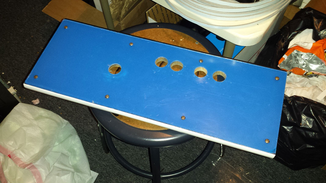
Building the Control Panel:The one and only place where I made changes to the original cabinet wood was the control panel. I considered buying a repo control panel wood and selling the original to someone doing a restore but the panel already had some extra screw holes in it and some weird cut out to make room for the non-original joystick that was in there so I figured making some additional non-visible changes wouldn't be any worse than what had already been done by the previous owner.
1. I completely depopulated the panel
2. With the control panel overlay still attached to the backing material I used an xacto knife to cut out the backing in the button hole locations. this gave me a template for where the 2nd button hole will need to be drilled. Lining these up with the existing joystick and button holes I drew a circle where the new button hole was to be located. I then drilled this out on my drill-press using a forstner bit.
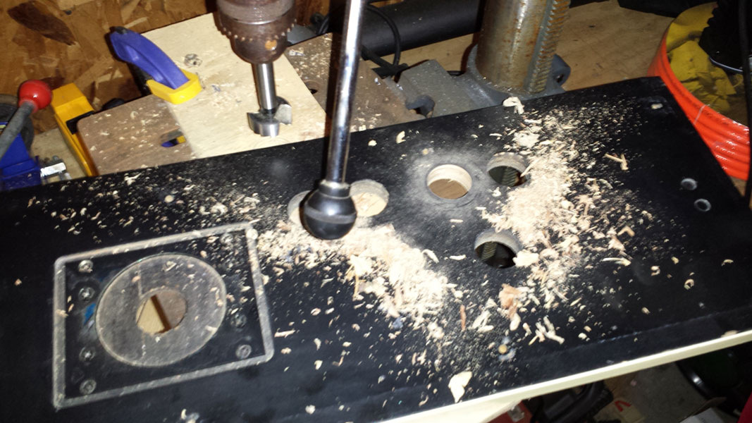
3. The lexan that I bought from TAP Plastics didn't have any holes so with the plastic protective sheet still in place, I clamped the control panel lexan into place over the control panel wood. Then I flipped it over and used the original bolt-holes in the wood as a guide to drill out 2 opposite corner holes in the lexian, using a block of wood on the other side of the plexi to help cleanly drill the hole. slow and steady is the key when drilling plastic so you don't crack or burn it. Once they were done I installed the original bolts into these holes to hold the plexi in place instead of the clamps
4. I then drilled out the remaining bolt holes and installing bolts after each hole was drilled. Once all of those were done I switched back to the forstner bit to drill the button and joystick holes in the plastic, again using the button holes int he wood as a guide to cut the matching holes in the plastic. Again, going slow with a block of wood on the other side for support. Once all the holes were drilled into the plexi I unbolted it from the wood and set it aside.
5. The servo stick with out the servo part would have bolted to the existing recess in the back of the control panel just fine but the servo board required the recess to be enlarged. I mocked up the stick and traced out the area that needed to be expanded then I used a Dremel with a cutting guide attachment to expand the recessed area. It got the job done quickly and easily but it was difficult to cut clean lines with it so the expanded section of the recess was a little rough around the edges. Had I something better than a Dremel for this job it could have been a lot cleaner but it's not terrible and it's not something you'll ever see with the machine all together.
6. The original Nintendo CPO is painted on to the back of the plastic, since I'm using a giant sticker the control panel surface needs to be smooth. unfortunately there's a big square recess for the joystick bolt plate and an additional recess for a dust washer, which I don't sticking to the back side of the art. I cut a square out of the photo matt material I had bought to use as a new black out bezel for the monitor. This ended up being the right thickness. I used an xacto to cut the edges to perfectly match the edges of the recess and then using the plexi as a guide to trace the position of the hole for the joystick; then cut that out with an Xacto knife.
7. I put the dust washer in place then put my piece of matt over the recess (which fit snug in the recess). then I used Redic Ricks video tutorial for applying a CPO to lay the CPO down over the control panel. After that I bolted down the plexi, mounted the buttons, then mounted the servo stick. I had a piece of really wide White T-molding left over from another cab that fit well for the front edge, it lined up perfectly with the top edge of the plexi and looks great. But because it isn't offset it hung below the bottom of the control panel a hair but it's really impossible to know unless you grab the lip of the control panel and I don't see a lot of people having reason to do that.
8. for wiring I salvaged the non-original control panel connector from the original harness then crimpted one end onto the JAMMa harness and the other end I crimped all new wires and connectors for the buttons and sticks. The Servo stick required an additional USB cable for the gate control module but thankfully there is plenty of slack in that and it unplugs easily from the module to make removing the control panel easy to do.

 PC Hardware:
I had a number of requirements for the hardware:
-able to output proper 15K video signal to the monitor
-compact enough to fit in the original PCB location
-reliable enough to run for hours and be ok if the power gets cut while running
-inexpensive
-low heat dissipation requirements/relatively quiet
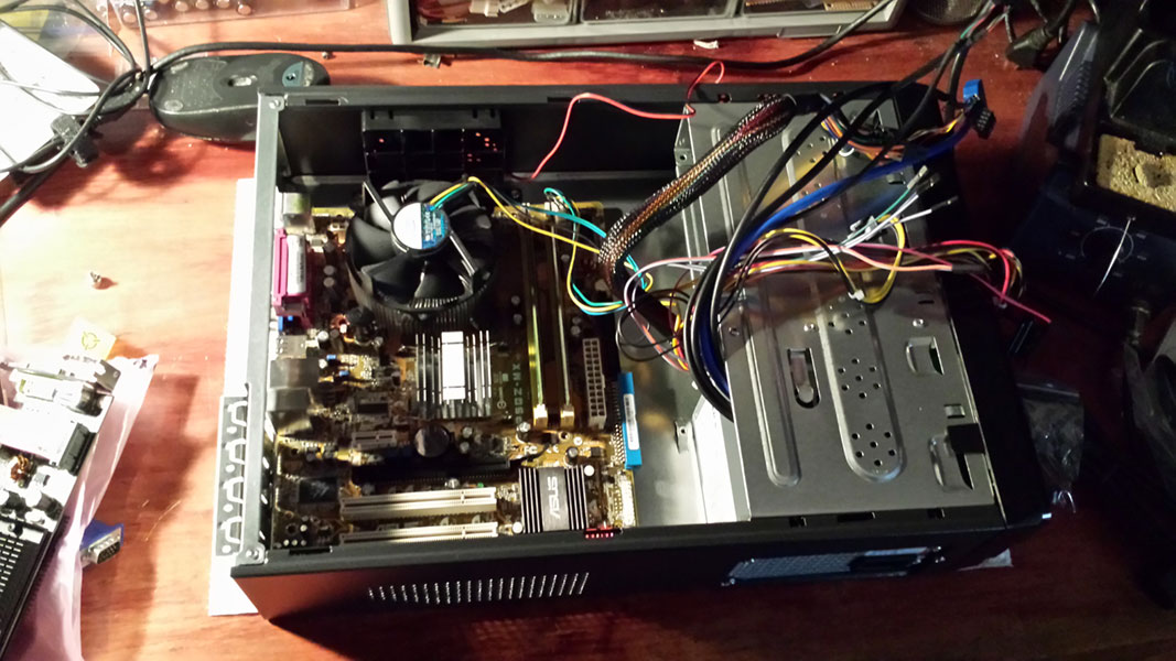
I opted to go for a MicroATX form factor PC with a low profile (aka: half-height) case. I found a used Core2Duo setup that included the motherboard, CPU fan and 2GB of ram on eBay for about $50. I bought a new low-profile HTPC style case that included a power supply and a few fans and I bought a new 128GB SSD Harddrive. SSD hard drives are great because they're not susceptible to physical damage the same way a normal hard drive is, they're much much faster than traditional hard drives and because they have no moving parts they're also completely silent. I don't need a lot of space to run a handful of MAME roms either so it's not like I need an enormous hard drive to make this work.
The hardest part to select was the graphics card. MAME doesn't use the GPU for processing the game code so you don't really need a fast GPU, BUT you DO need a graphics card that can output the 15K resolutions that the monitor requires. After many many days of research I decided that the 3 best options are: Ultimarc's ArcadeVGA, the Soft15Khz driver modification with a compatible card, or the CRT_EmuDriver modification with a compatible card... Ultimately I decided CRT_EmuDriver was the best option for my goals as it interacts with GroovyMAME to run every game at it's native resolution and is substantially cheaper than an ArcadeVGA setup. Not to mention Ultimarc doesn't make a low-profile version of the ArcadeVGA so it wouldn't fit into my case anyway.
The only problems with CRT_EmuDriver are that you're limited to your graphics card selection, as it only supports ATi cards and only certain families of cards. I opted for an ATi HD4350 which met all of those requirements: half-height, no fan, and CRT_EmuDriver compatible.
I needed to temporarily hook up a CD drive to install windows. In other builds since this I've actually installed windows from a bootable USB Thumb drive which I highly recommend. There is lots of information on how to do this on the web and it's pretty straight forward.
I made some tweaks in the bios to disable any of the on-board equipment that I wouldn't be using, I also went through and applied many of the tweaks found online for making XP boot and run faster. I also disabled windows update and removed any uneeded windows features as I want the machine to be as lean as possible.
Wiring and mounting:The original DK harness was custom built (poorly) and held together with hot glue so there was no love lost when I threw it in the trash. I decided to go with a J-PAC as the main method of interfacing the PC with the rest of the cab and used a generic JAMMA harness to tie there rest together. I sorted all of the wires on the harness into various bundles: wires for control panel, wires for coin door, wires for monitor, and unneeded wires. I de-pinned all of the unneeded wires, then for the control panel and monitor bundles I spliced in the matching connectors for those areas. The coin door wires I just hooked up directly.
Since I was using the original Sanyo 20EZ monitor I needed to use an inverter board (the original Nintendo monitors used an inverted signal so for non-Nintendo games you need to use an inverter board). This was an official Nintendo accessory for these monitors and I managed to buy one cheap from someone on KLOV. The plug I spliced into the JAMMA harness plugs into the inverter board which then plugs into the monitor input.
I also needed audio amplification for which I decided to use the original Sanyo 20EZ amp. For this I cut the end off of a 3.5mm audio patch-cable then spliced on a connector that would plug into the Sanyo 20EZ Amp board.
An arcade power supply is no longer needed since the PC has it's own Power supply but I do need somewhere to plug it in. I bought a standard power outlet and box from home depot, I thin wired it to the screw terminals that already exist inside the cab. There is an outlet in the old Nintendo cabs already but this is 100V (which is what Japan uses) not the 120V that US devices are designed to run on. I screwed the box to the cabinet base using existing screw holes from the non-original power supply
To mount everything in the ca I used some PCB feet to attach the JPAC to the PC case's side and then used a piece L-channel aluminum from Home Depot to make a bracket that would hold the top of the PC to the side of the cabinet. the weight of the PC is actually supported by the original PCB platform and I made another small metal bracket to seat the PC case into the original PCB channel. The two small screw holes on the upper bracket of the PC case are the only "modification" I've made to the entire cabinet.

I should note that after this picture was taken I swapped to a DVI to VGA converter cable for the PC to JPAC video interface, the reason being that CRT_EmuDriver only worked on the primary port of the video card which is almost always DVI.


 Home
Home Help
Help Search
 Login
Login Register

 Send this topic
 Print
Print Topic: Twistedsymphony's Fix it Felix Jr/MAME Cab (Read 14136 times)


