As the unclean abomination of
High Score Competition #124 Lode Runner 
(I keed, I keed

) draws to a close, here's a palate cleansing build for those of us who prefer playing the
best version of this game the way it was designed to be played -- on an Apple with a Kraft Premium analog joystick . . . or on M.E.S.S. with an updated version of the stick.


I had been looking since early July for a similar stick or an inexpensive analog stick controller to use like a UHID Nano or A-Pac from Ultimarc -- the only two easy options I found.
Last month, Degenatrons mentioned that,
I've also been testing with a KADE+ prototype (to be announced soon) which supports most of the original console controllers so have been using nes, snes, n64, gamecube, saturn, mastersystem, megadrive, tg16, atari 2600, psx controllers with Android.
Noticing that some of the controllers on that list have analog controls, I asked Jon if the analog controls were supported and offered to help with some beta testing.
Unlike the current KADE and the older AVR encoder, the KADE+ prototype is based on the ATMega32U4 chip which has built in Analog-to-Digital conversion circuitry.
The nice thing about the ATMega32U4 is that it is supposed to be compatible with all the current KADE firmwares -- for now, we have to recompile them and load them using FLIP (not as hard as it sounds

) until ATMega32U4 support is built into KADE Loader.
After just a few days of Degenatrons writing code for me to compile and load using FLIP (told you it wasn't that hard to do
) we had tested the basic A/D conversion and had a working hex file.
Degenatrons has given me permission to release a working copy of the hex file for anyone who wants to build an analog stick.
 ***2-Axis HEX File Download Link.******4-Axis HEX File Download Link.***
Directions for loading these firmwares on the board using FLIP are
here.
The source code won't be released until the KADE+ is released, however if someone needs a version compiled for a chip other than the ATMega32U4 let me know and I will recompile/post a hex file for that chip, but no promises on whether it will work and sorting out the correct pins is up to you.

The board that I'm using is the
MattairTech MT-DB-U4.
NOTE: If you order this board, select the 16 MHz clock and ATMEL DFU (FLIP) bootloader options.
There is also an option for pin headers, but you will need to solder those yourself.

In addition to being one of the boards used in development of KADE+, it's the smallest board with mounting holes.

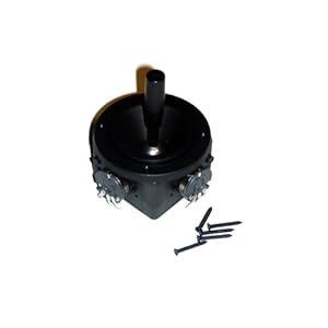
In addition to the board, you'll need a joystick like
this or
this or
this or
this or
this . . .
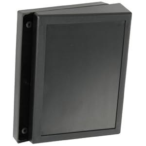
. . . a
project box like this . . .
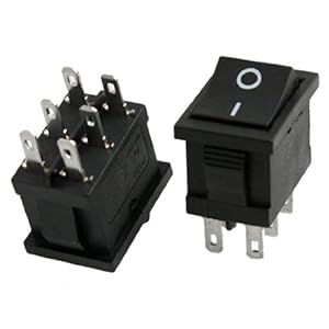
. . . a DPDT switch like
this . . .
. . . and a pair of Goldleaf buttons from Ultimarc or Arcadeemulator.net. (Divemaster127)

With all the pieces in place, let the build begin.
First, a template that fits into the recessed area on the project box.

The DPDT switch will be mounted on the back face of the project box.
Not sure if I'll go with red or black Goldleaf buttons so I test-fitted one of each along with the stick.


All joystick wires and button grounds soldered and tested good.

Found out later that the buttons and analog need separate grounds -- had to clip off the 0.110" daisy chain.

Next, I tried to polish out the squiggle next to the red button.

High speed on Dremel + my derpy "I'll learn how to polish plastic on the work piece" decision = several even worse marks.
Time for Plan B -- woodgrain vinyl for a bit of Atari 2600 vibe.

The thin gap in the lower right corner is almost impossible to see in normal lighting.
By this time, the DPDT switches arrived, so it's time to make some more sawdu. . . umm . . . plastic shavings.
The reason this stick will have a DPDT switch is that Apple ][ games like Lode Runner were written for the Kraft Premium Joystick.

The red button is button 1 and the black one is button 2.
In Lode Runner, the red button drills on your right and black drills on your left -- the opposite of standard arcade button order.

The DPDT switch changes which button is connected to which encoder input.

In the up position, Button A connects to Input 1 and Button B connects to Input 2.
Throw the switch and they change places.

The first step is to mark where to mount the switch.
Blue painters tape makes it easier to see the boundaries of the 0.7" x 0.5" mount hole.

The mount hole outline is horizontally centered between the buttons and vertically centered on the upper back face of the case.
After chain drilling with a very small bit near the perimeter, I used an X-Acto knife to carefully shave the plastic down to the outline on the tape.

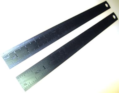
Protip: Use a tiny metal ruler like
this to check if sides are straight/square as you shave them.
Final fitting required a little bit longer hole than advertised, but it worked out perfectly with the switch bezel
barely covering the slight overshave on the sides. (I'll install the switch after soldering all the wires to it)

The hole is only .005 off-center vertically -- how the #&@% did I pull
that one off?

Still left to do:
- Get a grommet for the USB cable and maybe a 10k resistor (board spec sheet says it may be needed to prevent the board from randomly going into programming mode
)
- Cut the entry for the grommet
- Cut/solder the wires
- Final assembly
Scott


 Home
Home Help
Help Search
 Login
Login Register

 Send this topic
 Print
Print Topic: Analog Apple ][ KADESTICK (Read 27407 times)


