Main Restorations Software Audio/Jukebox/MP3 Everything Else Buy/Sell/Trade
Project Announcements Monitor/Video GroovyMAME Merit/JVL Touchscreen Meet Up Retail Vendors
Driving & Racing Woodworking Software Support Forums Consoles Project Arcade Reviews
Automated Projects Artwork Frontend Support Forums Pinball Forum Discussion Old Boards
Raspberry Pi & Dev Board controls.dat Linux Miscellaneous Arcade Wiki Discussion Old Archives
Lightguns Arcade1Up Try the site in https mode Site News

Unread posts | New Replies | Recent posts | Rules | Chatroom | Wiki | File Repository | RSS | Submit news


Author Topic: Analog Apple ][ KADESTICK  (Read 27340 times)

0 Members and 1 Guest are viewing this topic.

PL1

  • Global Moderator
  • Trade Count: (+1)
  • Full Member
  • *****
  • Offline Offline
  • Posts: 9401
  • Last login:Today at 10:37:59 am
  • Designated spam hunter
Re: Analog Apple ][ KADESTICK
« Reply #40 on: September 18, 2014, 03:39:21 pm »
It's not immediately clear from the thread what the runtime environment has to be here.  I'm probably going to use vectormame so I am likely going to be limited to an older version of windows or maybe even DOS itself. 
KADESTICK shows up as a USB HID joystick/gamepad.

Not sure what drivers might be needed for DOS/Win95/Win98/Win98SE/Win2k.   :dunno

XP or newer should work fine -- originally tested on a SP3 system.

If you get it working on an old system, please let us know how to do it.   :cheers:


Scott
« Last Edit: September 18, 2014, 03:41:28 pm by PL1 »

ChadTower

  • Chief Kicker - Nobody's perfect, including me. Fantastic body.
  • Trade Count: (+12)
  • Full Member
  • ***
  • Offline Offline
  • Posts: 38211
  • Last login:October 19, 2022, 12:01:54 pm
Re: Analog Apple ][ KADESTICK
« Reply #41 on: September 18, 2014, 03:59:45 pm »

Ah, nevermind.  I'm poking through all the stuff I had downloaded over the years and found versions of VectorMAME compiled for both linux and Windows.  The Windows version has this line in the instructions:

"If you're using Windows 7, turn off USER ACCESS CONTROLS."

Must be fairly recent.  :)

cmileski24

  • Trade Count: (0)
  • Jr. Member
  • **
  • Offline Offline
  • Posts: 4
  • Last login:February 12, 2015, 02:50:03 pm
  • I want to build my own arcade controls!
Re: Analog Apple ][ KADESTICK
« Reply #42 on: January 30, 2015, 07:05:13 am »
I was sent to your post from a reference. i bought the Kraft joystick to work with a MAME system. Im needing it for the old John Elway Quarterback Football game where the joystick acts as the control for passing the ball in the game, not as the joystick control for moving players. I have the Kraft joystick and have purchased the board you recommended in this post to transfer it from analog to digital. My question is what do I do to just use the joystick aspect? I don't need the buttons, therefore how do I wire it? would love your help with this since you have done some extensive work with it. I downloaded the hex file but not sure what to wire in order to make it work. Thanks so much. Here' s a copy of what the original controller looks like on the game.

PL1

  • Global Moderator
  • Trade Count: (+1)
  • Full Member
  • *****
  • Offline Offline
  • Posts: 9401
  • Last login:Today at 10:37:59 am
  • Designated spam hunter
Re: Analog Apple ][ KADESTICK
« Reply #43 on: January 30, 2015, 11:09:54 am »
My question is what do I do to just use the joystick aspect? I don't need the buttons, therefore how do I wire it?
Just ignore the button inputs.   ;D

For what you're doing, you need the following:

  1. The 10k pullup resistor between Vcc and E2/B to keep the board from going into programming mode every time it is plugged in.


  2. Wiper 1 to tab 2 of the Y-axis potentiometer. (blue wire below)

  3. Wiper 2 to tab 2 of the X-axis potentiometer. (green wire below)

  4. 5v to either tab 1 or tab 3 on the potentiometers and Gnd (Analog) to the other-- if an axis moves backward, swap 5v and Gnd (Analog) on that potentiometer.

PROTIP: Verify both axes are moving correctly before soldering the wires to tabs 1 and 3 -- alligator clips are your friend.


Here you can see the red 5v wire on tab 1 of both potentiometers and the black Gnd (Analog) wire on tab 3 of both potentiometers.


If you're wiring P2's analog joystick to the same board (using the 4-axis hex), connect 5v and Gnd (Analog) same as with P1's stick and connect the P2 potentiometer wipers to inputs F4 and F5. (I don't recall which wiper is which axis  :dunno)


Scott

danny_galaga

  • Grand high prophet of the holy noodle.
  • Trade Count: (+1)
  • Full Member
  • ***
  • Offline Offline
  • Posts: 8437
  • Last login:Yesterday at 10:23:15 pm
  • because the mail never stops
    • dans cocktail lounge
Re: Analog Apple ][ KADESTICK
« Reply #44 on: January 30, 2015, 06:22:51 pm »

SWEOMS!  :notworthy:


ROUGHING UP THE SUSPECT SINCE 1981

PL1

  • Global Moderator
  • Trade Count: (+1)
  • Full Member
  • *****
  • Offline Offline
  • Posts: 9401
  • Last login:Today at 10:37:59 am
  • Designated spam hunter
Re: Analog Apple ][ KADESTICK
« Reply #45 on: January 30, 2015, 07:13:02 pm »
SWEOMS!  :notworthy:
Umm . . . Thanks.   ???    ;D


Scott

PL1

  • Global Moderator
  • Trade Count: (+1)
  • Full Member
  • *****
  • Offline Offline
  • Posts: 9401
  • Last login:Today at 10:37:59 am
  • Designated spam hunter
Re: Analog Apple ][ KADESTICK
« Reply #46 on: November 03, 2015, 11:12:18 am »
How to Build a KADESTICK Yoke Interface

NOTE: The KADE miniArcade 2.0 firmware works with a variety of 32u4 AVRs if you'd like to use an AVR other than the MattairTech MT-DB-U4 or have trouble getting FLIP to work.  Pre-configured miniArcade 2.0 .dat file and wiring diagram for connecting a SW Yoke to an Arduino Pro Micro are here.

This tutorial was originially developed in this thread.


  Required skills:
Soldering - tutorial here.
Crimping molex pins - covered in step #7
Using a multimeter - covered in step #10

  Tools:
Multimeter
Wire strippers
Pin crimp tool (HT-336-FM with an HT-236-2U crimp die for 0.084" pins)
Pin removal tool (Optional -- This one is for 0.062" and 0.093" but it also works with 0.084")
Soldering iron
- Solder
- Flux
- Isopropyl alcohol (to clean after soldering)
- Q-tips and/or acid brush (to clean after soldering)
Needlenose pliers, foreceps, or wire-bending tool
3/32" security bit (to remove yoke cover) -- This set with 33 bits and this set with 100 bits both have the correct one
7/64" hex bit (to remove outer grips)
3/32" jeweler's screwdriver (to turn the terminal setscrews)

  Materials:
1 ea. - MattairTech MT-DB-U4 board -- select the 16 MHz crystal, ATMEL DFU (FLIP) bootloader, and "Headers Not Included" options.  *** Select "DFU (FLIP)" bootloader if you use KADE miniArcade 2.0 -- this bootloader does not require the 10k pullup resistor so you can skip steps 1-3. ***
1 ea. - USB 2.0 A Male to Mini-B 5 Pin Male cable (Similar to this one)
1 ea. - 10k Ohm resistor (1/8 watt or 1/4 watt)
1 ea. - 12 position euro-style terminal strip (only 10 terminal positions needed)
15-20 ft. - 22AWG (or similar) Wire -- stranded, not solid
Heat shrink
Mounting feet for board (if desired)
Loop clamps (Adel clamps)
Molex connector and pins that fit with the connector and pins on the yoke harness
- Star Wars yoke = Molex CONNECTOR PLUG 12POS .084 (part number 50-84-1120) with female pins. (part number 02-08-1004)
- Lock-On yoke = Molex 15 pos Receptacle 3x5 .062 (part number 03-06-1152) with female pins. (part number 02-06-1103)

  Downloads:
The firmware for the board - 2-Axis HEX File -- Special thanks to Degenatrons for giving me permission to release a working copy of the hex file for anyone who wants to build an analog stick/yoke interface.   :notworthy:   :notworthy:
FLIP 3.4.7 (or higher) to load the firmware onto the board - https://www.microchip.com/developmenttools/ProductDetails/FLIP
  or
Use the KADE miniArcade 2.0 firmware and Mapper program in place of that 2-Axis HEX File and FLIP.
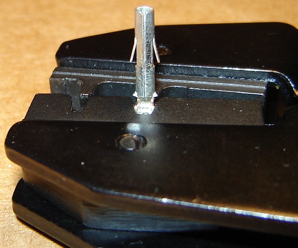
  Procedure:
1. Cut/strip/lightly tin a 2.5" - 3" wire and and bend one end into a U-shaped loop.  Cut one lead of the 10k ohm "pullup" resistor to ~1/4" and bend it into a U-shaped loop.


2. Solder the wire loop to the resistor loop (shown below with the end of a wire-bending tool) and insulate the connection with heat-shrink.


3. Solder the resistor and wire between the Vcc and E2/B holes on the board.


4. Use FLIP to load the firmware on the board using the procedures here.

5. Solder 4" wires to the following 10 board holes:

* Gnd (lower right) - Ground (Buttons)
* B0 - Button 1 (left trigger)
* B1 - Button 2 (right trigger)
* B2 - Button 3 (left thumb button)
* B3 - Button 4 (right thumb button)
* Agnd - Ground (Analog)
* F1 - X-axis Wiper
* F0 - Y-axis Wiper
* Avcc - 5v for Analog
* Gnd (lower left) - Frame ground

You may want to use color coded wires.


6. Connect the 10 board wires to the terminal strip. (strip shown was cut to 10 positions)


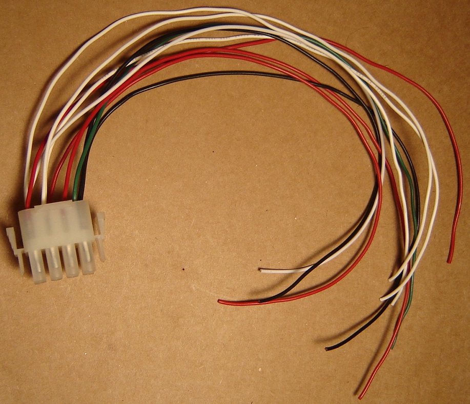
7. Make a Molex adapter cable.
- You may want to use color coded wires that match with your yoke harness.
- Crimp pins onto enough 12"(?) lengths of wire to connect each pin from the yoke harness to the terminal strip.

-- The "14" slot on the HT-236-2U die works well for 0.084" pins

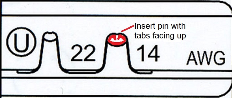
-- Pic below shows a molex pin properly positioned in the jaws of a ratchet crimper with the wire end of the pin toward the slightly wider side of the crimp die, the "ears" on the pin pointing into the U-shaped side of the crimp die and the already-round part of the pin clear of the crimp die by just over a thumbnail-thickness.


- Insert the crimped pins into the molex housing.


8. Attach the Molex adapter cable to the yoke harness.

9. Carefully remove the outer grips (don't lose the springs on the thumb buttons or triggers) and the cover from the yoke so you can check the wiring.


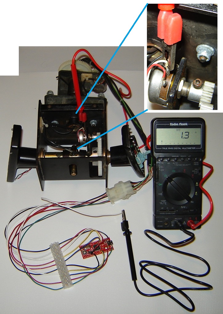
10. Verify the wiring using your multimeter set to either continuity or ohms mode.
- Clip one lead of your multimeter to a wire in the yoke and touch the other lead to one wire after another in the molex adapter cable until you hear a beep (continuity mode) or read less than 2 ohms. (ohms mode)
- Connect that wire to the associated terminal on the strip -- some terminals may have more than one molex wire connected
- Repeat until all molex wires are identified and connected to the correct terminal.

Pic shows continuity from Y-axis potentiometer wiper (red lead) to the corresponding wire on pin 5 of the molex adapter cable. (black lead)


Star Wars harness pinout (Thanks to Ninten-doh for the original image and to Gray_Area for clarifying the wording)


Hydra harness pinout (Thanks to processedmeat.)
NOTE: This pinout and wire colors may not be factory defaults.  If you have an un-hacked harness, please confirm and/or clarify.
I'm not as confident about the harness colors as the previous owner seemed to do a hack job on the wiring.  But those are definitely the pinouts as confirmed by the multimeter.


Lock-On harness pinout (Thanks to greenmanjph.)


Terminals


11. Mount the board and terminal strip.  Add Loop clamps as needed for strain relief.

12. Test/calibrate the yoke and interface using Windows gamepad properties.

NOTE: Do not use a game to do this, since the game/emulator software adds more variables.


Troubleshooting
Axis reversed (i.e. crosshairs moving left when the yoke is turned to the right)
Reverse the axis by swapping the 5v and ground wires on tabs 1 and 3 of the pot.

Jitter (i.e. shaky crosshairs)
Jitter can be caused by the pots and/or the wires. (probably the pots)

To eliminate the wires, use a jumper wire with insulated alligator clips or a screwdriver to short the center tab (wiper) of the pot to either the tab with 5v or ground.

If the wires/connections are good, the crosshairs should go all the way to the edge of the box and stay there without jitter.
- Jitter when shorting to 5v, but not when shorting to ground = bad 5v wire/connection
- Jitter when shorting to ground, but not when shorting to 5v = bad ground wire/connection
- Jitter when shorting wiper to 5v and when shorting wiper to ground = bad wiper wire/connection

If the wires/connections all check good,that just leaves the pots.


Scott
« Last Edit: April 25, 2020, 12:32:15 am by PL1 »

g_block247

  • Trade Count: (0)
  • Full Member
  • ***
  • Offline Offline
  • Posts: 56
  • Last login:March 29, 2016, 03:46:56 pm
Re: Analog Apple ][ KADESTICK
« Reply #47 on: March 29, 2016, 10:13:49 am »
this is EXACTLY what I've been looking for with a couple changes (the size form and two buttons are dead on!!!)

a 4 way red ball top joystick in place of the joystick that you're using, a player one button up in the top right hand corner and a credit button where the power switch goes (like this one - http://groovygamegear.com/webstore/index.php?main_page=product_info&products_id=295)

any chance you'd do another one with those changes and how much would it cost (I'm guessing in the $80-$100 ballpark for the time/work plus parts.)

nice work on it.

PL1

  • Global Moderator
  • Trade Count: (+1)
  • Full Member
  • *****
  • Offline Offline
  • Posts: 9401
  • Last login:Today at 10:37:59 am
  • Designated spam hunter
Re: Analog Apple ][ KADESTICK
« Reply #48 on: March 29, 2016, 11:40:46 am »
this is EXACTLY what I've been looking for with a couple changes (the size form and two buttons are dead on!!!)

a 4 way red ball top joystick in place of the joystick that you're using, a player one button up in the top right hand corner and a credit button where the power switch goes (like this one - http://groovygamegear.com/webstore/index.php?main_page=product_info&products_id=295)
Check out the size comparisons in the attached pics.

The joystick is a Zippyy and the button is similar to the CDR you linked.

A CDR-style rectangular button is twice as wide, twice as long, and more than twice as deep as the DPDT "power switch".

I don't see how either of these will fit into the case.

GeoMan did several small stand-alone controllers like this one that are a much better fit for what you are describing -- check out the other links in his sig, too.   ;D

any chance you'd do another one with those changes and how much would it cost (I'm guessing in the $80-$100 ballpark for the time/work plus parts.)
I'm more than happy to answer any questions but don't have any desire or time to build KADESTICKs for sale.

nice work on it.
Thanks.   :cheers:


Scott
« Last Edit: March 29, 2016, 12:09:02 pm by PL1 »